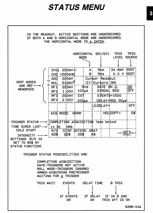
Tektronix 2440 digital oscilloscope
Display REF button: Call the reference waveform (REF1-REF4) to switch the horizontal position adjustment mode.
Basic operation process (from startup to signal display)
3.1 Startup and self-test process
Power on preparation: Connect the 3-pin power supply (ensure grounding), press the POWER button below the front panel;
Self check process: The instrument automatically performs a power on self-test, and the screen displays "RUNNING SELF TEST". After completion, the prompt disappears;
Self check passed: directly enter oscilloscope mode, CAL/DIAG menu displays "PASS";
Self check failure: Enter extended diagnostic mode, the screen displays the fault area, press MENU OFF to exit and enter oscilloscope mode (temporary use when the fault does not affect measurement);
Preheating waiting: Within 10 minutes after starting up, the CAL/DIAG menu displays "NOT WARMED UP", during which it is not recommended to perform calibration or high-precision measurements;
Parameter initialization:
Connect probe: 10X probe connected to CH1 BNC, probe tip connected to instrument CALIBRATION circuit( 2.5V@1kHz Square wave), ground wire connected to oscilloscope ground;
Call initial settings: Press PRGM SETUP → press the bezel key (no label button at the bottom of the screen) to select "Initiat PANEL", load default parameters (CH1 activation, 1V/div, 1ms/div, AUTO LEVEL trigger, 1M Ω DC coupling);
Verification channel: Confirm that the CH1 VOLT/DIV reading is displayed in the upper left corner of the CRT. If it is not displayed, press Vertical MODE → Select CH1.
3.2 Signal Capture and Optimization
Signal connection: Connect the probe tip to the measured signal and the ground wire to the signal reference ground (shorten the length of the ground wire as much as possible to reduce noise);
Automatic optimization: Press the AUTO SETUP button, and the instrument will automatically adjust the vertical sensitivity, horizontal time base, and trigger level, displaying 2-5 signal cycles;
Manual fine-tuning:
Vertical adjustment: If the waveform is truncated, turn the VOLTS/DIV knob clockwise (to reduce sensitivity); If the waveform is too small, adjust counterclockwise;
Horizontal adjustment: If the signal period is displayed too much/too little, adjust the SEC/DIV knob (fast time base displays less period, slow time base displays more period);
Trigger optimization: If the trigger is unstable, press Initiat @ 50% or manually turn the TRIGGER LEVEL knob to ensure that the trigger point is on the edge of signal stability.

Detailed analysis of core functions
4.1 Vertical system (signal amplitude control)
4.1. Key functional operations
Coupling mode selection: Press the COUPLING button on CH1/CH2 to cycle through AC/DC/GND:
DC coupling: retaining the AC+DC components of the signal (such as measuring ripple with DC offset);
AC coupling: Block the DC component and only display the AC signal (such as measuring the amplitude of the AC signal);
GND coupling: Disconnect signal input and display ground reference line (used for calibrating vertical position);
ADD/MULT mode usage:
ADD mode: CH1 and CH2 signals are superimposed, and the CH1 VARIABLE knob can adjust the amplitude of CH2 signal to cancel interference (such as eliminating power noise);
MULT mode: The CH1 and CH2 signals are multiplied, and the result is automatically reduced by 5.12 times to adapt to the screen range (such as measuring power signals);
Bandwidth restriction application: When high-frequency noise interference occurs, press the BANDWIDTH button to select 20MHz/100MHz restriction to filter out high-frequency noise (such as selecting 20MHz bandwidth when measuring 50Hz power signals).
4.1.2 Common problem troubleshooting
No waveform display: Check if the coupling mode is GND → switch to AC/DC; Check if the probe is securely connected → Re plug and unplug the probe;
Waveform truncation: VOLTS/DIV sensitivity is too high → adjust clockwise to increase the gear;
High waveform noise: switch to AC coupling → enable bandwidth limitation → shorten the length of the probe ground wire.
4.2 Horizontal System (Signal Timing Control)
4.2.1 A/B dual time base operation
A time base (regular mode): Press the A button to activate, adjust the time base with SEC/DIV knob, and when ≤ 100ms/div, the AUTO trigger mode will automatically switch to ROLL mode (waveform scrolling display from left to right, suitable for slow signals);
B time base (delayed scan):
Press the B button to activate, and switch the SEC/DIV knob to control the B time base;
Adjust the A time base to display the complete signal, and adjust the B time base to amplify the signal locally (such as amplifying the rising edge of the pulse);
Press the A INTEN button, and the screen will display the A enhanced area (the local signal amplified by the B time base) for easy observation of details.
4.2.2 Trigger position adjustment
Press the TRIG POSITION button to cycle through the trigger positions (1/8, 1/4, 1/2, 3/4, 7/8):
Trigger position is 1/8: More display signals after triggering (such as observing the attenuation process after pulse triggering);
Trigger position is 7/8: more display of pre trigger signals (such as capturing interference pulses before triggering);
- ABB
- General Electric
- EMERSON
- Honeywell
- HIMA
- ALSTOM
- Rolls-Royce
- MOTOROLA
- Rockwell
- Siemens
- Woodward
- YOKOGAWA
- FOXBORO
- KOLLMORGEN
- MOOG
- KB
- YAMAHA
- BENDER
- TEKTRONIX
- Westinghouse
- AMAT
- AB
- XYCOM
- Yaskawa
- B&R
- Schneider
- Kongsberg
- NI
- WATLOW
- ProSoft
- SEW
- ADVANCED
- Reliance
- TRICONEX
- METSO
- MAN
- Advantest
- STUDER
- KONGSBERG
- DANAHER MOTION
- Bently
- Galil
- EATON
- MOLEX
- Triconex
- DEIF
- B&W
- ZYGO
- Aerotech
- DANFOSS
- Beijer
- Moxa
- Rexroth
- Johnson
- WAGO
- TOSHIBA
- BMCM
- SMC
- HITACHI
- HIRSCHMANN
- Application field
- XP POWER
- CTI
- TRICON
- STOBER
- Thinklogical
- Horner Automation
- Meggitt
- Fanuc
- Baldor


