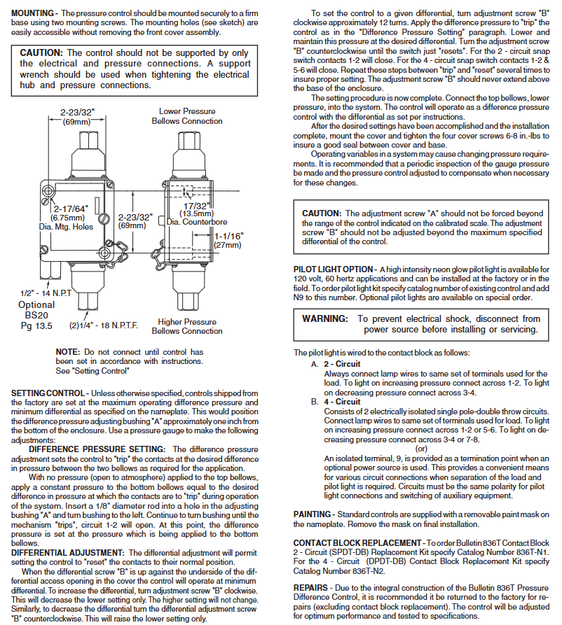
Rockwell Automation 836T Series Differential Pressure Controller
Protection ability: It can resist oil/water flow erosion, prevent cotton wool and dust from entering the shell, and is suitable for scenarios that require environmental sealing.
Insert a 1/8 "diameter rod into the hole of the adjusting sleeve" A ", rotate the sleeve to the left until the controller" triggers "(circuit 1-2 is disconnected, circuit 1-2 and 5-6 are disconnected);
At this point, the pressure of the bottom corrugated tube is the set trigger pressure difference.
2. Differential Adjustment Control
Adjustment logic: Adjusting screw "B" only changes the reset pressure difference (does not affect the triggering pressure difference) - turn screw "B" clockwise → increase the control pressure difference (reset pressure difference decreases); Turn counterclockwise → reduce the control pressure difference (reset pressure difference increases); When screw "B" is tightened against the bottom of the front cover, control the pressure difference to be minimized.
Specific steps:
Rotate screw "B" clockwise for about 12 turns;
Apply pressure according to the "trigger pressure difference setting" steps to trigger the controller, then reduce the pressure to the target control pressure difference and maintain it;
Rotate screw "B" counterclockwise until the controller is "reset" (2 circuits 1-2 are closed, 4 circuits 1-2, 5-6 are closed);
Repeat the "trigger reset" cycle several times to ensure stable settings;
Screw "B" should not protrude from the bottom of the housing, and adjusting sleeve "A" should not exceed the control range marked on the dial.
3. Complete the setup
After parameter calibration, connect the top corrugated pipe (low pressure end) to the system, install the front cover and tighten 4 screws (torque 6-8 inch pounds) to ensure sealing. It is recommended to regularly check the system pressure and recalibrate as needed.
Optional accessories and maintenance
1. Pilot Light Options
Specification: High brightness neon lamp, suitable for 120V, 60Hz scenes, can be pre installed in the factory or installed on site;
Ordering method: Add "N9" (such as 836T-XXX-N9) after the existing controller model, special specifications require customization;
Wiring rules:
2-channel circuit: Connect the light wire to the load terminal, connect 1-2 for "on when pressure rises" and 3-4 for "on when pressure drops";
4-channel circuit: Connect the light wire to the load terminal (1-2/5-6 or 3-4/7-8), or connect it to an external power source through isolation terminal 9 (ensuring the same polarity of the circuit);
Safety reminder: Disconnect the power supply before installation/maintenance to prevent electric shock.
2. Component replacement and maintenance
Contact module replacement: 2-channel module replacement kit model 836T-N1, 4-channel module kit model 836T-N2;
Overall maintenance: As the controller is an integrated structure, it is recommended to return all faults except for the contact module to the factory for repair (the factory will calibrate to the best performance and test according to specifications);
Nameplate protection: The standard controller nameplate comes with a removable protective film, which needs to be removed during final installation.
Safety and Compliance
CE certification: The product complies with CE standards;
Operation warning: Adjust the components within the marked range to avoid mechanical damage; Corrosive media should use 316 stainless steel corrugated pipes to prevent material failure;
WEEE and Environmental Protection: The document does not mention specific environmental compliance information, please refer to Rockwell Automation's General Environmental Policy.

- ABB
- General Electric
- EMERSON
- Honeywell
- HIMA
- ALSTOM
- Rolls-Royce
- MOTOROLA
- Rockwell
- Siemens
- Woodward
- YOKOGAWA
- FOXBORO
- KOLLMORGEN
- MOOG
- KB
- YAMAHA
- BENDER
- TEKTRONIX
- Westinghouse
- AMAT
- AB
- XYCOM
- Yaskawa
- B&R
- Schneider
- Kongsberg
- NI
- WATLOW
- ProSoft
- SEW
- ADVANCED
- Reliance
- TRICONEX
- METSO
- MAN
- Advantest
- STUDER
- KONGSBERG
- DANAHER MOTION
- Bently
- Galil
- EATON
- MOLEX
- DEIF
- B&W
- ZYGO
- Aerotech
- DANFOSS
- Beijer
- Moxa
- Rexroth
- Johnson
- WAGO
- TOSHIBA
- BMCM
- SMC
- HITACHI
- HIRSCHMANN
- Application field
- XP POWER
- CTI
- TRICON
- STOBER
- Thinklogical
- Horner Automation
- Meggitt
- Fanuc
- Baldor
- SHINKAWA
- Other Brands


