
Rockwell Automation 836T Series Differential Pressure Controller
Protection ability: It can resist oil/water flow erosion, prevent cotton wool and dust from entering the shell, and is suitable for scenarios that require environmental sealing.
Rockwell Automation 836T Series Differential Pressure Controller
Product Core Description
1. Basic specifications and applicable scenarios
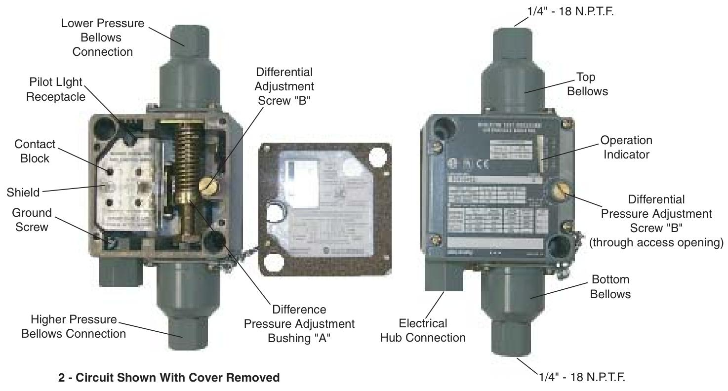
Model classification: Bulletin 836T, including three types: Type 1, 4, and 13, all designed to be oil tight.
Protection ability: It can resist oil/water flow erosion, prevent cotton wool and dust from entering the shell, and is suitable for scenarios that require environmental sealing.
Connection specifications: The pressure interface is 1/4 "-18 N.P.T.F (American dry sealed cone pipe thread), and the electrical interface includes 1/2" -14 N.P.T (optional Pg 13.5 BS20 specification).
Bellows material: provides two options, each suitable for different media——
Copper alloy corrugated pipe: suitable for water, air, and non corrosive liquids/gases;
316 stainless steel corrugated pipe: suitable for liquids/gases with stronger corrosiveness.
2. Core Structure and Function
Core components: including Top Bellows, Bottom Bellows (mechanical linkage), Contact Block, Adjustment Differential Screw "B", Pressure Adjustment Difference Bushing "A", Operation Indicator, optional Pilot Light, etc.
Pressure sensing principle: The action is triggered by the pressure difference between two corrugated tubes, regardless of the actual gauge pressure of the system; Adjustable "trip pressure" and "reset pressure", with the difference between the two being the "differential control pressure".
Contact module configuration: provides two specifications to meet different circuit requirements——
Contact module type Contact configuration Circuit function
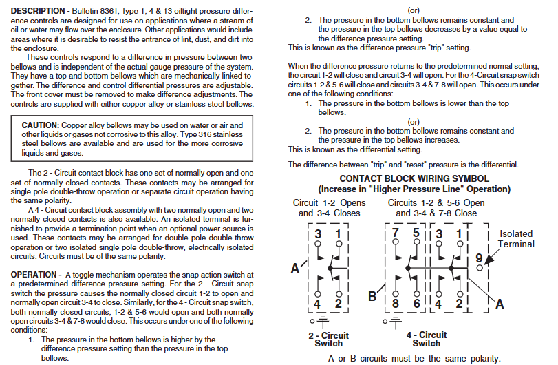
2-circuit: 1 set of normally open (NO)+1 set of normally closed (NC) supports single pole double throw (SPDT) or independent circuit operation with the same polarity
4-circuit with 2 sets of normally open (NO) and 2 sets of normally closed (NC) supports double pole double throw (DPDT) or two sets of electrically isolated single pole double throw circuits, including isolated terminal 9, which can be connected to external power supply
Working principle
The controller responds to pressure difference changes through a "trigger reset" cycle, with the following specific logic:
1. Trigger (Trip) action (contact switching)
When any of the following conditions are met, the contact module switches states:
The pressure of the bottom corrugated pipe is higher than the preset trigger pressure difference of the top corrugated pipe;
The pressure of the bottom corrugated tube is constant, and the pressure of the top corrugated tube decreases by the preset trigger pressure difference.
2-channel circuit: normally closed circuit (1-2) is open, normally open circuit (3-4) is closed;
4-channel circuit: Two sets of normally closed circuits (1-2, 5-6) are disconnected, and two sets of normally open circuits (3-4, 7-8) are closed.
2. Reset action (contact recovery)
When any of the following conditions are met, the contact returns to its initial state:
The pressure of the bottom corrugated pipe is lower than that of the top corrugated pipe;
The pressure of the bottom corrugated pipe remains constant, while the pressure of the top corrugated pipe increases.
2-channel circuit: normally closed circuit (1-2) is closed, normally open circuit (3-4) is open;
4-channel circuit: Two sets of normally closed circuits (1-2, 5-6) are closed, and two sets of normally open circuits (3-4, 7-8) are disconnected.
3. Key definitions
Trip Pressure: The minimum pressure difference required to trigger contact switching;
Reset Pressure: The maximum pressure difference that triggers contact recovery;
Differential control: The difference between the trigger pressure and the reset pressure can be independently adjusted.
Installation requirements
1. Mechanical installation
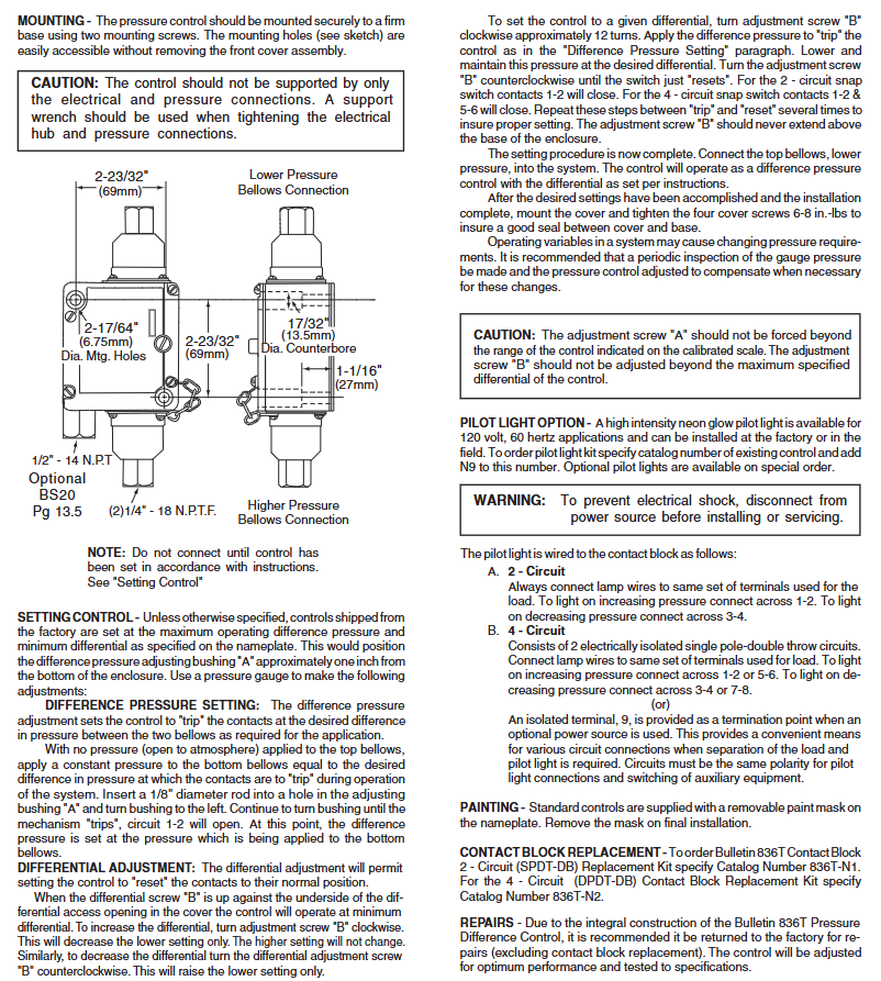
Fixing method: It needs to be fixed on a stable base with two screws, and the installation hole specification is "2-17/64" diameter (6.75mm)+2-23/32 "countersunk hole (69mm)", which can be operated without disassembling the front cover;
Prohibited operation: Do not support the controller solely through electrical or pressure interfaces; When tightening the electrical and pressure interfaces, a support wrench should be used to avoid damaging the components.
2. Precautions for Pre Installation
Before installation, it is necessary to complete the parameter settings ("Setting Control" steps) according to the instructions, otherwise the system cannot be connected;
The pressure interface distinguishes between the "Lower Pressure Bellows Connection" and the "Higher Pressure Bellows Connection", which need to be connected to the corresponding system.
Parameter setting steps
The factory default setting is "maximum trigger pressure difference+minimum control pressure difference" (adjusting the sleeve "A" about 1 inch from the bottom of the housing), which requires the assistance of a pressure gauge for calibration. It is divided into two steps:
1. Trigger the Difference Pressure Setting
The top corrugated pipe is vented to the atmosphere (without pressure), and a constant pressure is applied to the bottom corrugated pipe to trigger the target pressure difference;
Insert a 1/8 "diameter rod into the hole of the adjusting sleeve" A ", rotate the sleeve to the left until the controller" triggers "(circuit 1-2 is disconnected, circuit 1-2 and 5-6 are disconnected);
At this point, the pressure of the bottom corrugated tube is the set trigger pressure difference.
2. Differential Adjustment Control
Adjustment logic: Adjusting screw "B" only changes the reset pressure difference (does not affect the triggering pressure difference) - turn screw "B" clockwise → increase the control pressure difference (reset pressure difference decreases); Turn counterclockwise → reduce the control pressure difference (reset pressure difference increases); When screw "B" is tightened against the bottom of the front cover, control the pressure difference to be minimized.
Specific steps:
Rotate screw "B" clockwise for about 12 turns;
Apply pressure according to the "trigger pressure difference setting" steps to trigger the controller, then reduce the pressure to the target control pressure difference and maintain it;
Rotate screw "B" counterclockwise until the controller is "reset" (2 circuits 1-2 are closed, 4 circuits 1-2, 5-6 are closed);
Repeat the "trigger reset" cycle several times to ensure stable settings;
Screw "B" should not protrude from the bottom of the housing, and adjusting sleeve "A" should not exceed the control range marked on the dial.
3. Complete the setup
After parameter calibration, connect the top corrugated pipe (low pressure end) to the system, install the front cover and tighten 4 screws (torque 6-8 inch pounds) to ensure sealing. It is recommended to regularly check the system pressure and recalibrate as needed.
Optional accessories and maintenance
1. Pilot Light Options
Specification: High brightness neon lamp, suitable for 120V, 60Hz scenes, can be pre installed in the factory or installed on site;
Ordering method: Add "N9" (such as 836T-XXX-N9) after the existing controller model, special specifications require customization;
Wiring rules:
2-channel circuit: Connect the light wire to the load terminal, connect 1-2 for "on when pressure rises" and 3-4 for "on when pressure drops";
4-channel circuit: Connect the light wire to the load terminal (1-2/5-6 or 3-4/7-8), or connect it to an external power source through isolation terminal 9 (ensuring the same polarity of the circuit);
Safety reminder: Disconnect the power supply before installation/maintenance to prevent electric shock.
2. Component replacement and maintenance
Contact module replacement: 2-channel module replacement kit model 836T-N1, 4-channel module kit model 836T-N2;
Overall maintenance: As the controller is an integrated structure, it is recommended to return all faults except for the contact module to the factory for repair (the factory will calibrate to the best performance and test according to specifications);
Nameplate protection: The standard controller nameplate comes with a removable protective film, which needs to be removed during final installation.
Safety and Compliance
CE certification: The product complies with CE standards;
Operation warning: Adjust the components within the marked range to avoid mechanical damage; Corrosive media should use 316 stainless steel corrugated pipes to prevent material failure;
WEEE and Environmental Protection: The document does not mention specific environmental compliance information, please refer to Rockwell Automation's General Environmental Policy.
- OMRON
- ABB
- General Electric
- EMERSON
- Honeywell
- HIMA
- ALSTOM
- Rolls-Royce
- MOTOROLA
- Rockwell
- Siemens
- Woodward
- YOKOGAWA
- FOXBORO
- KOLLMORGEN
- MOOG
- KB
- YAMAHA
- BENDER
- TEKTRONIX
- Westinghouse
- AMAT
- AB
- XYCOM
- Yaskawa
- B&R
- Schneider
- KONGSBERG
- NI
- WATLOW
- ProSoft
- SEW
- ADVANCED
- Reliance
- TRICONEX
- METSO
- MAN
- Advantest
- STUDER
- DANAHER MOTION
- Bently
- Galil
- EATON
- MOLEX
- DEIF
- B&W
- ZYGO
- Aerotech
- DANFOSS
- Beijer
- Moxa
- Rexroth
- Johnson
- WAGO
- TOSHIBA
- BMCM
- SMC
- HITACHI
- HIRSCHMANN
- Application field
- XP POWER
- CTI
- TRICON
- STOBER
- Thinklogical
- Horner Automation
- Meggitt
- Fanuc
- Baldor
- SHINKAWA
- Other Brands
- UniOP
- KUKA
- Iba
- Beckhoff
-
 Basler Electric DECS-200-1L Digital Excitation Control System
 -
 Basler DECS125-15-B2C1 Excitation Control
 -
 Basler 9507900205 SSR Retrofit Voltage Regulator
 -
 Basler BE2000E Digital Voltage Regulator
 -
 Basler BE1-GPS Generator Protection System
 -
 Basler DECS-250-CN1CN1N Digital Excitation Control
 -
 Basler DGC-2020 Genset Controller
 -
 Basler BE1-81O UT3ED1LA7N0F Frequency Relay (Variant)
 -
 Basler BE1-81O UT3EE1YA9S0F Frequency Relay (Variant)
 -
 Basler BE1-81O Over/Under Frequency Relay
 -
 Basler DECS125-15 Digital Excitation Control
 -
 Basler Electric BE1-951 Overcurrent Protection System
 -
 Basler Electric BE1-700V Digital Protective Relay
 -
 Basler Electric APR63-5 Automatic Voltage Regulator
 -
 Basler Electric BE1-851 Overcurrent Protection System
 -
 Basler Electric DECS-250-LN1SN1N Excitation Control
 -
 Basler Electric BE1-87T Transformer Differential Relay
 -
 Basler Electric DECS-200-1L Excitation Control System
 -
 Basler Electric 9310300100 DECS-300 Excitation Control
 -
 Basler Electric SSE-N 125-4.5KW Shunt Exciter Regulator
 -
 Basler Electric DGC-2020HD-5NS1DNSBA Genset Controller
 -
Basler Electric BE1-81-O/UT3EE1JB7N1F Frequency Relay
-
 Basler Electric BE1-81T1EE1WA0N1F Frequency Relay
 -
 Basler Electric BE1-25M1EA6PN5R1F Sync-Check Relay
 -
 Basler Electric BE1-GPS Generator Protection System
 -
Basler Electric DECS-250-LN1SN1N Excitation Control Rev V
-
 Basler Electric DECS-250-CN2CN1N Excitation Control
 -
 Basler Electric BE1-50/51B-207 Overcurrent Relay
 -
Basler Electric DECS-300-C0N0 Excitation Control System
-
Basler Electric DECS-200 Digital Excitation Control System
-
Basler Electric DECS-250-LN1CN1N Excitation Unit
-
Basler Electric DECS-250 LN2SA1D Excitation Unit Specs
-
Basler Electric BE1-87T Transformer Relay Review
-
Basler Electric BE1-11 Protection System
-
Basler Electric BE1-GPS100-E4N1H1N Protection System
-
 Allen-Bradley 442G-MABH-R Safety Module
 -
 Beckhoff CX1030-0111 PLC Assembly Profile
 -
 FANUC IC693CPU364 PLC Module
 -
 Orange Denmark Type 200816 220 PLC Specs
 -
 OMRON C200H-SNT31 Sysmac PLC Module
 -
 Allen Bradley 20AB022A3AYNANC0 PowerFlex 70
 -
 OMRON C200HW-PCU01 Position Control Unit
 -
 ABB AO845A-eA Analog Output Module
 -
 OMRON CJ1M-CPU22 CPU Unit
 -
 Allen Bradley 100-E265ED11 Contactor
 -
 Honeywell 51304511-100 Interface Module
 -
 SOLEXY BXF3S0101N0018 Gateway Module
 -
 OMRON CJ2H-CPU65 CPU Unit
 -
 Automation Direct GS2-45P0 AC Drive
 -
 M68-2000 2-Axis Motion CNC Controller
 -
 OMRON CJ1M-CPU11 V3.0 PLC CPU Unit
 -
 OMRON CJ1W-NC413 4-Axis Positioning Controller
 -
 OMRON 3G2A3-PRO16 Programming Console HMI
 -
 Siemens 3VT8440-2AA04-2GA2 Molded Case Circuit Breaker
 -
 Siemens 3RT5045 Contactor Series
 -
 OMRON C200HS-CPU01-E SYSMAC PLC Controller
 -
 OMRON C500-NC103-E Positioning Control Unit
 -
 OMRON CJ1W-TC001 Temperature Control Unit
 -
 OMRON NJ301-1100 NJ-PA3001 PLC System EtherCAT
 -
 Pilz 773100 M1P Safety Relay Base Unit
 -
 Siemens SINUMERIK 840D SL NCU 720.3B with PLC 317-3 PN/DP
 -
 Siemens 6AV6618-7GD01-3AB0 HMI Panel
 -
 OMRON F150-C15E-3 Vision Mate Controller PLC Overview
 -
 Mitsubishi MELSEC A Series PLC System A63P A3ACPU A616AD A68RD3
 -
 M68-2000 2 Axis Motion Controller SCE SERVO CNC
 -
 OMRON FZ-S2M PLC Camera Vision System
 -
 VISOLUX SLVA-4K PLC Module from Elektronik GmbH
 -
 OMRON CJ1M-CPU23 V2.0 PLC CPU Unit
 -
 ABB AI86-16CHF PCB Card 5761751-9 B Specifications
 -
 Allen-Bradley 100-D140ZJ22L Contactor Overview
 -
 Merlin Gerin PB80 PLC Rack
 -
 WEIR WE203 Power Supply PLC
 -
 OMRON NX-TS3102 Temperature Input Unit
 -
 Siemens 6ES7146-6FF00-0AB0 I/O Module
 -
 Fanuc A16B-3300-0057 Circuit Board
 -
 OMRON CJ1W-IDP01 Input Module
 -
 Siemens 6FX2007-1AD13 Handheld Unit
 -
 Gems EM54 PLC Module PCB
 -
 Beckhoff CX2030-0121 Embedded PC CPU
 -
 OMRON NJ301-1100 Machine Automation Controller
 -
 Biesse Rover CNI PLC 2153 030 7146.30 Numerical Control Module
 -
 OMRON CJ1W DA08V Analog Output Module
 -
 OMRON CS1D ETN21D Ethernet Module
 -
 Allen Bradley 1768 L43 CompactLogix Controller
 -
 Schneider TWDLMDA40DTK Twido PLC Module
 -
 Mitsubishi NZ2EX2B 60AD4 Analog Input Module
 -
 OMRON NS8 TV00B V2 Touch Display Panel
 -
 Mitsubishi AY71 CMOS TTL Output Module
 -
 OMRON C500 CPU11 E Processor Module
 -
 OMRON CJ1W PTS51 Temperature Input Module
 -
 Siemens 6SL3100-1DE22-0AA1 600V DC Supply
 -
 OMRON CJ1M-CPU23 PLC CPU 9‑Pin Serial
 -
 Schlumberger IMT4N 24‑250VAC 48‑230VAC PLC Timer
 -
 OMRON CJ1M-CPU22 PLC CPU Unit V2.0
 -
 Allen‑Bradley 2711P-B7C6D2 Touch Screen PanelView
 -
 ADSP-2181KST-160 Analog Devices DSP IC Specs
 -
 Schneider LC1F400 400A Contactor Specifications
 -
 Yaskawa SGDH-10DE-OY 1kW 400V Servo Drive
 -
 Schneider TM262L10MESE8T M262 PLC 5ns Inst
 -
 Mitsubishi AA104VJ05 10.4in LCD Panel Specs
 -
 Allen Bradley 1761-L32BWA MicroLogix 1000 PLC
 -
 Siemens 6ES7431-7KF00-0AB0 Analog Input Module
 -
 Allen Bradley 1769-OB16 Output Module
 -
 Siemens 6ES7131-1BL12-0XB0 Input Module
 -
 Beckhoff EP7041-3002 EtherCAT Box Module
 -
 Siemens RK7243-2AA30-0XB0 Communication Module
 -
 Siemens 4AM5742-8DD40-0FA0 Transformer
 -
 Siemens 3TK2834-1BB40 Safety Relay
 -
 Brother BAS 311 Sewing Machine Circuit Board
 -
Yaskawa SGDH-10DE-OY Servo Driver
-
 OMRON C60H C6DR DE V1 Sysmac PLC
 -
 MITSUBISHI ELECTRIC A2ACPU21 S1 CPU Module
 -
 ABB BAILEY INNPM12 Network Process Module
 -
 HONEYWELL 620 0073C IPC PLC Module
 -
 Mitsubishi 15050 PR02B PLC Circuit Board
 -
 SIEMENS 6SY7000 0AC37 Drive Control Module
 -
 OMRON TJ2 ECT16 Traxial EtherCAT Controller
 -
 GE Fanuc IC698PSD300D Power Supply Module
 -
 Texas Instruments Series 505 16 Position Base
 -
 OMRON YASKAWA SGDH 10DE OY Servo Drive
 -
 Allen‑Bradley 440G-MT Safety Interlock Switch Specs
 -
 Rubycon PD27A 24V 8A Power Supply Module
 -
 SK-H1-GDB1-F11D PLC Gate Driver Board Kit
 -
 VIPA 441-4UA14 451-4UA14 PLC Module Rack
 -
 Mitsubishi FX5U-80MT ESS PLC Controller Specs
 -
 Mitsubishi Q64TCRTN Temperature PLC Module
 -
 GE 1C31170G Rev10 PLC Circuit Board Module
 -
 Schneider TWDLMDA40DTK PLC Controller Module


