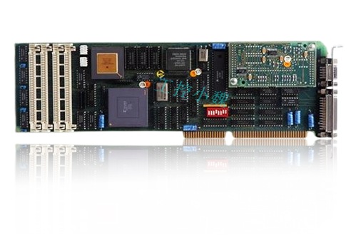
HIMatrix Safety-Related Controller F35 01 Manual
3. Protect the HIMatrix F35 with a 10 A time-lag fuse.
The 24 VDC power must come from a power supply unit with safe isolation. Use power supply units of type PELV or SELV only.
4. Applicable standards:
VDE 0170/0171 Part 16, DIN EN 60079-15: 2004-5
VDE 0165 Part 1, DIN EN 60079-14: 1998-08
Pay particular attention to the following sections:
DIN EN 60079-15:
Chapter 5 Design
Chapter 6 Terminals and cabling
Chapter 7 Air and creeping distances
Chapter 14 Connectors
DIN EN 60079-14:
Chapter 5.2.3 Equipment for use in zone 2
Chapter 9.3 Cabling for zones 1 and 2
Chapter 12.2 Equipment for zones 1 and 2
Configuration with SILworX
In the Hardware Editor, the controller is represented like a base plate equipped with the
following modules:
{1} Processor module (CPU)
{2} Communication module (COM)
{3} Output module (DO 8)
{4} Counter module (HSC 2)
{5} Input module (MI 24/8)
Double-click the module to open the Detail View with the corresponding tabs. The tabs are used to assign the global variables configured in the user program to the system variables of the corresponding module.
3. Parameters and Error Codes for the Inputs and Outputs
The following tables specify the system parameters that can be read and set for the inputs and outputs, including the corresponding error codes.In the user program, the error codes can be read using the variables assigned within the logic.The error codes can also be displayed in SILworX.Configuration with ELOP II Factory
3.1 Configuring the Inputs and Outputs
The signals previously defined in the Signal Editor (Hardware Management) are assigned to the individual channels (inputs and outputs) using ELOP II Factory. Refer to the system manual for compact systems or the online help for more details.The following chapter describes the system signals used for assigning signals in the controller.
3.2 Signals and Error Codes for the Inputs and Outputs
The following tables specify the system signals that can be read and set for the inputs and outputs, including the corresponding error codes.In the user program, the error codes can be read using the signals assigned within the logic.The error codes can also be displayed in ELOP II Factory.
Connection Variants:
This chapter describes the permissible wiring of the controller in safety-related applications.Only the connection variants specified here are permitted for SIL 3 applications.
3.3 Wired Mechanical Contacts on Analog Inputs
Wired mechanical contacts are connected to the analog inputs using the Z 7308 shunt adapter,see Figure 11. The shunt adapter protects the analog inputs against overvoltage and shortcircuits from the field zone.Each analog input has a supply output that is fed by a common AI power source. The supply voltage is between 26.7 V and 27.3 V.The supply of the analog inputs must be monitored. To do so, the used supply outputs (S1...S8)must be connected in parallel and attached to a digital input. The evaluation of the digital input is analog and must be configured in the programming tool accordingly.

Maintenance
No maintenance measures are required during normal operation.If a failure occurs, the defective module or device must be replaced with a module or device of the same type or with a replacement model approved by HIMA.Only the manufacturer is authorized to repair the device/module.
4. Faults
Refer to Chapter 3.1.1.1, for more information on the fault reaction of digital inputs.
Refer to Chapter 3.1.2.1, for more information on the fault reaction of digital outputs.
Refer to Chapter 3.1.3.1, for more information on the fault reaction of counters.
Refer to Chapter 3.1.4.2, for more information on the fault reaction of analog inputs.
If the test harnesses detect safety-critical faults, the module enters the STOP_INVALID state and will remain in this state. This means that the input signals are no longer processed by the device and the outputs switch to the de-energized, safe state. The evaluation of diagnostics provides information on the fault cause.
4.1 Maintenance Measures
The following measures are required for the device:
{1} Loading the operating system, if a new version is required
{2} Executing the proof test
4.2 Loading the Operating System
HIMA is continuously improving the operating system of the devices. HIMA recommends to use system downtimes to load a current version of the operating system into the devices.Refer to the release list to check the consequences of the new operation system version on the system!The operating system is loaded using the programming tool.Prior to loading the operating system, the device must be in STOP (displayed in the programming tool). Otherwise, stop the device.For more information, refer to the programming tool documentation.
4.3 Proof Test
HIMatrix devices and modules must be subjected to a proof test in intervals of 10 years. Formore information, refer to the safety anual (HI 800 023 E).
- ABB
- General Electric
- EMERSON
- Honeywell
- HIMA
- ALSTOM
- Rolls-Royce
- MOTOROLA
- Rockwell
- Siemens
- Woodward
- YOKOGAWA
- FOXBORO
- KOLLMORGEN
- MOOG
- KB
- YAMAHA
- BENDER
- TEKTRONIX
- Westinghouse
- AMAT
- AB
- XYCOM
- Yaskawa
- B&R
- Schneider
- Kongsberg
- NI
- WATLOW
- ProSoft
- SEW
- ADVANCED
- Reliance
- TRICONEX
- METSO
- MAN
- Advantest
- STUDER
- KONGSBERG
- DANAHER MOTION
- Bently
- Galil
- EATON
- MOLEX
- DEIF
- B&W
- ZYGO
- Aerotech
- DANFOSS
- Beijer
- Moxa
- Rexroth
- Johnson
- WAGO
- TOSHIBA
- BMCM
- SMC
- HITACHI
- HIRSCHMANN
- Application field
- XP POWER
- CTI
- TRICON
- STOBER
- Thinklogical
- Horner Automation
- Meggitt
- Fanuc
- Baldor
- SHINKAWA
- Other Brands


