
KOLLMORGEN AKD ® Servo drive fault card
AKD ® Servo drive fault card
Basic Information
Scope of application: This fault card is applicable to Kollmorgen AKD series servo drives (hardware revision E), covering standard and AKD-T models (supporting BASIC program function). It provides a detailed list of fault/warning codes, causes, remedies, and drive responses, and is the core reference document for troubleshooting.
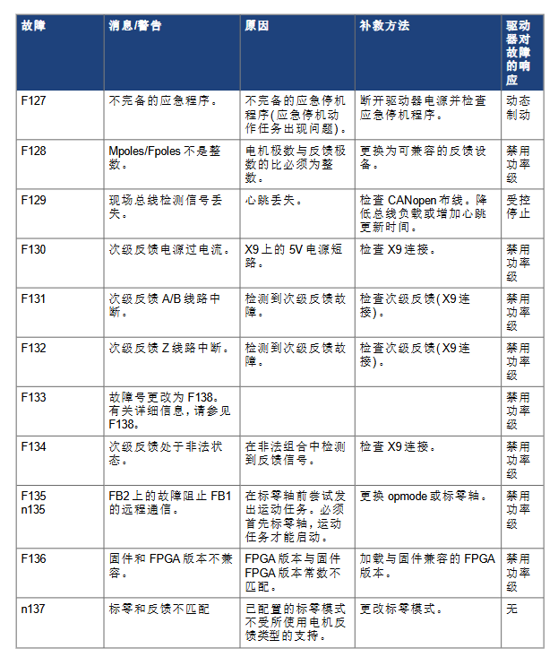
Version iteration: The document has undergone 13 revisions (A-M version), with the latest M version (November 2020) updating code descriptions such as F470 (feedback 3 fault) and F583/n583 (Hall effect sorting error). Historical versions have added key fault entries such as F314 (motor phase loss), F587 (full AC input phase loss), and F634 (failure of regenerator test).
Supporting tools: Fault information can be viewed through the driver panel display (single/dual 7-segment screen), LED indicator lights (screenless models), or WorkBench software. It supports reading the fault list through the DRV.FAULTRAS/DRV.Warning commands, which can be called by external controllers/HMIs to obtain information.
Basic explanation of faults and warnings
(1) Indicator type and display rules
Equipment configuration fault/warning indication display logic
The left side of the dual 7-segment display shows "F" (fault) or "n" (warning), and the right side displays a 3-digit code (such as F101, n107) to prioritize the highest priority fault. When there are multiple faults, they are displayed in turn
Single 7-segment display flashes in the order of "F/n+code" (such as "F" first, then "1", "0", "1"), following the same dual screen logic. The complete code needs to be identified through the flashing sequence
Only the LED indicator light flashing red indicates a fault, while flashing yellow indicates a warning. WorkBench needs to be connected to view the specific code
(2) Drive fault response type
Controlled shutdown: Slow down the motion to zero speed (parameter CS.VTHRESH/CS-TO defines threshold), then disable the power level, suitable for non emergency faults (such as F121 zero error, F438 position following error).
Immediately disable power level (coasting stop): Cut off the motor power directly and allow the motor to coast freely to a stop, suitable for hardware failures (such as F101 firmware incompatibility, F201 built-in RAM damage).
Dynamic braking: By short circuiting the motor phase to slow down the load, it is suitable for dangerous faults (such as F302 overspeed, F404 illegal Hall state), and attention should be paid to the mechanical stress during the braking process.
Extended response (AKD-C central power supply): In addition to the driver's own response, it will also disconnect the power fault relay, remove the global enable signal, and even cut off the logical voltage of the device string (such as F545 device string overcurrent).
Core fault classification and typical codes
(1) Hardware and firmware failures (F100-F299)
1. Firmware and FPGA related
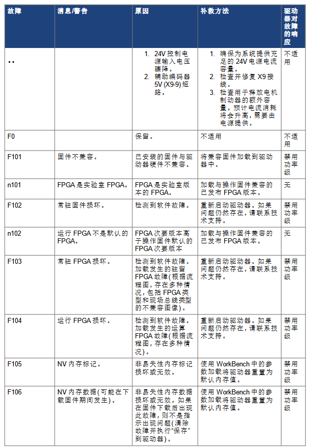
F101 (firmware incompatible): The installed firmware does not match the hardware of the drive, and compatible firmware needs to be loaded (e.g. UCB1V2 label model requires firmware ≥ 4.0.0).
F103/F104 (FPGA damage): The resident/running FPGA detects a software malfunction, and restarting is ineffective. Technical support should be contacted, and it may be necessary to return to the factory for repair.
N101/n102 (FPGA version exception): The laboratory version FPGA or minor version does not match the firmware, and an official compatible FPGA version must be loaded.
2. Memory and hardware failures
F105/F106 (NV memory error): Non volatile memory flag/data corruption, reset default parameters through WorkBench loading, F106 is normal after firmware download (fault needs to be cleared and parameters saved).
F201-F203 (RAM/code integrity failure): Internal/external RAM is damaged or FPGA register access is incorrect, restarting is ineffective and the driver needs to be replaced.
F234-F243 (temperature sensor malfunction): The sensor is at ultra-high temperature (F-level) or ultra-low temperature (F-level). Check the ventilation of the cabinet and clean the heat dissipation channel.
(2) Motor and feedback faults (F300-F499)
1. Motor related
F301/n301 (motor overheating): The motor temperature exceeds the threshold. Check the ambient temperature, radiator installation, reduce load or optimize the motion curve.
F302 (overspeed): If the motor speed exceeds VL.THRESH, it is necessary to increase the threshold or decrease the speed command, and dynamic braking will be triggered in emergency situations.
F304/n304 (motor current feedback): Exceeding the maximum motor power, check if the load is stuck and if the current limit is correct, and optimize the motion configuration by reducing acceleration.
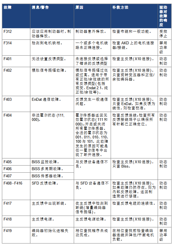
F314 (motor phase loss): The motor phase wire is not connected correctly. Check the AKD motor connector wiring (if the U/V/W phase is loose), disable the power level, and repair it.
2. Feedback related
F401 (Invalid Feedback Type): Feedback type not connected or selected incorrectly. Check the wiring of the main feedback (X10 interface) and confirm that the feedback type (such as EnDat, BiSS, rotary transformer) is consistent with the parameter configuration.
F404 (Illegal Hall State): The Hall sensor returns 111/000 (the legal state is 001/010/011/100/101), check if the Hall wiring is broken or has poor contact, and trigger dynamic braking protection.
F438/n438 (position following error): The actual position exceeds the maximum allowable deviation. Check if the load has increased, if the feedback commutation setting is correct, and adjust the servo gain or position deviation threshold.
F470 (Feedback 3 Fault): The third level feedback (X9 interface) is not connected or communication is abnormal. Check FB3.FAULTRA for detailed information, repair the wiring or replace the feedback device.
(3) Power supply and power level faults (F500-F599)
1. Bus voltage related
F501/n501 (Bus Overvoltage): The bus voltage exceeds the threshold, often due to high regenerative energy of the load. It is necessary to reduce the load, optimize the deceleration curve, or increase the regenerative resistance capacity.
F502 (bus undervoltage): If the bus voltage is below the threshold, check if the input power supply is stable, check if the power supply wiring is loose or if there is a power supply fault, and trigger a controlled shutdown.
F503 (Bus capacitor overload): Connect the three-phase driver to a single-phase input or ultra single-phase load, confirm the power phase wiring (L1/L2/L3), and replace the matching power supply.
2. Power level and regeneration faults
F519 (short circuit in regeneration circuit): The regeneration resistor or IGBT is short circuited. It is necessary to disconnect the power supply and check the resistance wiring. Contact technical support to replace the power components.
F521/n521 (regeneration circuit over power): The power of the regeneration resistor is insufficient. Replace it with a larger capacity resistor or enable DC bus sharing, and disable power level protection equipment.
F525 (output overcurrent): If the current exceeds the peak value of the driver, check if the motor is short circuited and if there is a feedback fault. Urgently disable the power level to prevent hardware damage.
F531 (power level fault): Power level hardware fault, restart is ineffective and the driver needs to be replaced, which is a fatal fault.
(4) Fieldbus and communication failure (F600-F799)
F602 (Safety Torque Off, STO): Trigger the STO function, confirm safety conditions, and then power on again, in accordance with functional safety specifications (such as EN ISO 13849).
F702/n702 (fieldbus communication disconnected): All fieldbus communication is lost. Check the X11 interface wiring (such as EtherCAT, CANopen), host settings, and trigger controlled shutdown.
F706/n706 (fieldbus set point loss): The host stops sending set points due to timeout. Check the stability of the bus connection, reduce the bus load, or adjust the timeout parameter.
(5) AKD-T exclusive fault (F800-F999)
AKD-T supports running BASIC programs, and many faults are related to program execution. The typical code is as follows:
F801 (divided by zero): There is a division by zero operation in the program, modify the code to avoid invalid calculations.
F802 (Stack Overflow): Insufficient program stack memory, optimize code structure, reduce nested calls.
F824/F825 (mode incompatible): DRV.OPMODE needs to be set to 2 (position mode), DRV.CMDSOURCE needs to be set to 5 (program command), adjust the parameters and restart the program.
F901 (Too Many Cams): The number of cams defined in the program exceeds the upper limit, reduce cam configuration or optimize motion logic.
Key fault troubleshooting process
Identification code: Obtain the fault code through panel display or WorkBench, confirm the code type (F/n) and priority.
Identify the cause: Based on the corresponding entries on the fault card, investigate the hardware wiring (such as feedback, power supply, motor phase lines), parameter configuration (such as feedback type, current limit), and environmental conditions (temperature, ventilation).
Execute remedial measures:
Wiring faults (such as F314 motor phase loss, F404 Hall wire breakage): Repair the wiring after power failure, and confirm the correctness of the connection before re enabling.
Parameter faults (such as F105 NV memory error, F501 bus overvoltage): Reset parameters or adjust thresholds through WorkBench, save and restart the drive.
Hardware failures (such as F201 RAM damage, F531 power level failure): If restarting is ineffective, please contact technical support and return to the factory for repair if necessary.
Clear the fault: Use the DRV.CLRFAULTS command or WorkBench button to clear the fault, confirm that the fault is eliminated, and then re enable the drive.
- OMRON
- ABB
- General Electric
- EMERSON
- Honeywell
- HIMA
- ALSTOM
- Rolls-Royce
- MOTOROLA
- Rockwell
- Siemens
- Woodward
- YOKOGAWA
- FOXBORO
- KOLLMORGEN
- MOOG
- KB
- YAMAHA
- BENDER
- TEKTRONIX
- Westinghouse
- AMAT
- AB
- XYCOM
- Yaskawa
- B&R
- Schneider
- KONGSBERG
- NI
- WATLOW
- ProSoft
- SEW
- ADVANCED
- Reliance
- TRICONEX
- METSO
- MAN
- Advantest
- STUDER
- DANAHER MOTION
- Bently
- Galil
- EATON
- MOLEX
- DEIF
- B&W
- ZYGO
- Aerotech
- DANFOSS
- Beijer
- Moxa
- Rexroth
- Johnson
- WAGO
- TOSHIBA
- BMCM
- SMC
- HITACHI
- HIRSCHMANN
- Application field
- XP POWER
- CTI
- TRICON
- STOBER
- Thinklogical
- Horner Automation
- Meggitt
- Fanuc
- Baldor
- SHINKAWA
- Other Brands
- UniOP
- KUKA
- Iba
- Beckhoff
-
 Basler D90 96801 100 PCB Card
 -
 Basler XR2002F Voltage Regulator (110 VAC, 48-480 Hz)
 -
 Basler SR8A-2B14B3A Regulator
 -
 Basler 9561500100 Module
 -
 Basler DECS-400 BE1-11 System
 -
 Basler DECS-100-B15 Excitation Control
 -
 Basler SCP 210 Frequency Controller
 -
 Basler SR4A-2B15B3A Static Voltage Regulator
 -
 Basler BE1-32R Power Relay
 -
 Basler PIA2400-17GM Power Interface Adapter
 -
 Basler MVC 232 Manual Voltage Control Module
 -
 Basler SSR 32-12 Static Voltage Regulator
 -
 Basler 5MW AVR Generator Voltage Regulator
 -
 Basler VR63-4B Voltage Regulator
 -
 Basler DECS-100-A05 AVR for Engine Generator
 -
 Basler DECS-100-B15 Automatic Voltage Regulator
 -
 Basler BE1-32R Directional Power Relay
 -
 Basler BE1-87B Differential Relay
 -
 Basler UFOV 260A Protective Module
 -
 Basler 9-2614-02-100 PCB Rev M
 -
Basler DECS-100-B15 Digital AVR
-
 Basler 9284900103 PS DECS-400N
 -
 Basler D4N3H1U Intertie Protection
 -
 Basler DECS-100-B15 A15 AVR
 -
 Basler KR4F Voltage Regulator
 -
 Basler BE26434 T14 Transformer
 -
 Basler SR8A-2B15B3A Regulator
 -
 Westinghouse 774B472A12 AR Relay
 -
Basler DECS-100-B15 AVR
-
Basler XR2002F Regulator 110V
-
Basler SR125-E Static Regulator
-
 Basler SSR 125-12 Regulator
 -
 Basler MOC2599 Motor Pot
 -
 Basler BE1-DFPR Feeder Relay
 -
 Basler CBS 305 Current Boost
 -
 Basler BE1-25 AutoSync
 -
 Basler MVC 300 Voltage Control
 -
 Basler BE3-25A AutoSync
 -
 Basler KR7FF Static Regulator
 -
 Basler 90-49000-100 Regulator
 -
 Basler 880 kVA Dry Type Transformer Specs
 -
 Basler Electric BE1-25 Sync-Check Relay Specs
 -
 Basler SSR 125-12 Voltage Regulator Specs
 -
 Basler Electric BE1-851 Overcurrent Relay Review
 -
Basler Electric 149D930G02 Control Sub-Assembly
-
 Basler Electric BE1-81O/UT Frequency Relay Specs
 -
 Basler Electric BE1-51/27C Overcurrent Relay
 -
 Basler Electric 149D956G02 Industrial Component
 -
Basler Electric BE1-51A Overcurrent Relay Specs
-
 Basler Electric BE1-40Q Loss of Excitation Relay
 -
 Basler DECS-200 Excitation Control System
 -
 Basler DECS-200 Voltage Regulator 56-277V AC / 125V DC
 -
Basler BE1-87T Transformer Differential Relay
-
 Basler RDP-110-S1 Protection Relay
 -
 Basler BE1-700V Digital Protective Relay
 -
 Basler BE1-951 Overcurrent Protection System
 -
 Basler DECS-300 Digital Excitation Control
 -
 Basler DECS-200 Digital Excitation Control
 -
 Basler DECS-200-1C Excitation Control System
 -
Basler DECS-200-1L Digital Excitation Control
-
 Basler Electric BE1-GPS Generator Protection System
 -
Basler Electric DECS-200-1C Digital Excitation Controller
-
 Basler Electric DECS125-15 Excitation Control with Power Module
 -
 Basler Electric BE1-87G Differential Relay
 -
 Basler Electric BE1-11 Protection System I5A3M2P2N0EA00
 -
Basler Electric DECS-200-1C Excitation Control System
-
Basler Electric BE1-11g Generator Protection Relay
-
Basler Electric DECS 125-15-B2C1 V2.0.9 Excitation Control
-
 Basler Electric BE1-81O/UT3ED1JA7N2F Frequency Relay
 -
Basler Electric BE1-81O/UT3EE1YB7N1F Frequency Relay
-
 Basler Electric DECS-200-1L Digital Excitation Control System
 -
Basler DECS125-15-B2C1 Excitation Control
-
 Basler 9507900205 SSR Retrofit Voltage Regulator
 -
 Basler BE2000E Digital Voltage Regulator
 -
 Basler BE1-GPS Generator Protection System
 -
Basler DECS-250-CN1CN1N Digital Excitation Control
-
 Basler DGC-2020 Genset Controller
 -
 Basler BE1-81O UT3ED1LA7N0F Frequency Relay (Variant)
 -
 Basler BE1-81O UT3EE1YA9S0F Frequency Relay (Variant)
 -
Basler BE1-81O Over/Under Frequency Relay
-
Basler DECS125-15 Digital Excitation Control
-
Basler Electric BE1-951 Overcurrent Protection System
-
 Basler Electric BE1-700V Digital Protective Relay
 -
 Basler Electric APR63-5 Automatic Voltage Regulator
 -
Basler Electric BE1-851 Overcurrent Protection System
-
Basler Electric DECS-250-LN1SN1N Excitation Control
-
 Basler Electric BE1-87T Transformer Differential Relay
 -
Basler Electric DECS-200-1L Excitation Control System
-
 Basler Electric 9310300100 DECS-300 Excitation Control
 -
 Basler Electric SSE-N 125-4.5KW Shunt Exciter Regulator
 -
 Basler Electric DGC-2020HD-5NS1DNSBA Genset Controller
 -
Basler Electric BE1-81-O/UT3EE1JB7N1F Frequency Relay
-
Basler Electric BE1-81T1EE1WA0N1F Frequency Relay
-
 Basler Electric BE1-25M1EA6PN5R1F Sync-Check Relay
 -
 Basler Electric BE1-GPS Generator Protection System
 -
Basler Electric DECS-250-LN1SN1N Excitation Control Rev V
-
 Basler Electric DECS-250-CN2CN1N Excitation Control
 -
Basler Electric BE1-50/51B-207 Overcurrent Relay
-
Basler Electric DECS-300-C0N0 Excitation Control System
-
Basler Electric DECS-200 Digital Excitation Control System
-
Basler Electric DECS-250-LN1CN1N Excitation Unit
-
Basler Electric DECS-250 LN2SA1D Excitation Unit Specs
-
Basler Electric BE1-87T Transformer Relay Review
-
Basler Electric BE1-11 Protection System
-
Basler Electric BE1-GPS100-E4N1H1N Protection System
-
 Allen-Bradley 442G-MABH-R Safety Module
 -
 Beckhoff CX1030-0111 PLC Assembly Profile
 -
 FANUC IC693CPU364 PLC Module
 -
 Orange Denmark Type 200816 220 PLC Specs
 -
 OMRON C200H-SNT31 Sysmac PLC Module
 -
 Allen Bradley 20AB022A3AYNANC0 PowerFlex 70
 -
 OMRON C200HW-PCU01 Position Control Unit
 -
 ABB AO845A-eA Analog Output Module
 -
 OMRON CJ1M-CPU22 CPU Unit
 -
 Allen Bradley 100-E265ED11 Contactor
 -
 Honeywell 51304511-100 Interface Module
 -
 SOLEXY BXF3S0101N0018 Gateway Module
 -
 OMRON CJ2H-CPU65 CPU Unit
 -
 Automation Direct GS2-45P0 AC Drive
 -
 M68-2000 2-Axis Motion CNC Controller
 -
 OMRON CJ1M-CPU11 V3.0 PLC CPU Unit
 -
 OMRON CJ1W-NC413 4-Axis Positioning Controller
 -
 OMRON 3G2A3-PRO16 Programming Console HMI
 -
 Siemens 3VT8440-2AA04-2GA2 Molded Case Circuit Breaker
 -
 Siemens 3RT5045 Contactor Series
 -
 OMRON C200HS-CPU01-E SYSMAC PLC Controller
 -
 OMRON C500-NC103-E Positioning Control Unit
 -
 OMRON CJ1W-TC001 Temperature Control Unit


