How to install and maintain the ABB CP450 Human Machine Interface (HMI)?
Display and interaction: Equipped with a 10.4-inch TFT color LCD screen (64K colors, 640 × 480 pixels), analog touch screen, backlight life of about 50000 hours (at 25 ° C environment), supports 80 × 60 characters (8 × 8 fonts) display, and can ensure operational accuracy through touch screen calibration.
Protection level: The front panel meets IP65/NEMA 4X standards (for indoor use only), is dustproof and waterproof, and is suitable for industrial pollution level 2 environments (moderate dust, no strong corrosive gases).
Compatibility and development tools: Application programs need to be designed using CP400Soft software, supporting compatibility with multiple HMI models and providing "plug and play" on-site device integration capabilities to reduce development difficulty.
Anti interference and stability: It has high transient anti-interference capability, meets the requirements of Article 4 of EMC Directive 2004/108/EC, and can operate stably in an environment without strong magnetic fields or drastic temperature changes (working temperature of 0-50 ° C).
Installation process (including key steps)
1. Inspection of packaging list
After unpacking, it is necessary to confirm that the following components are included. If they are missing, please contact the supplier:
1 CP450 operator terminal;
8 installation fasteners;
1 24V DC power connector (pre installed on the device);
One installation and operation manual (1SBC159105M0202).
2. Opening and fixing
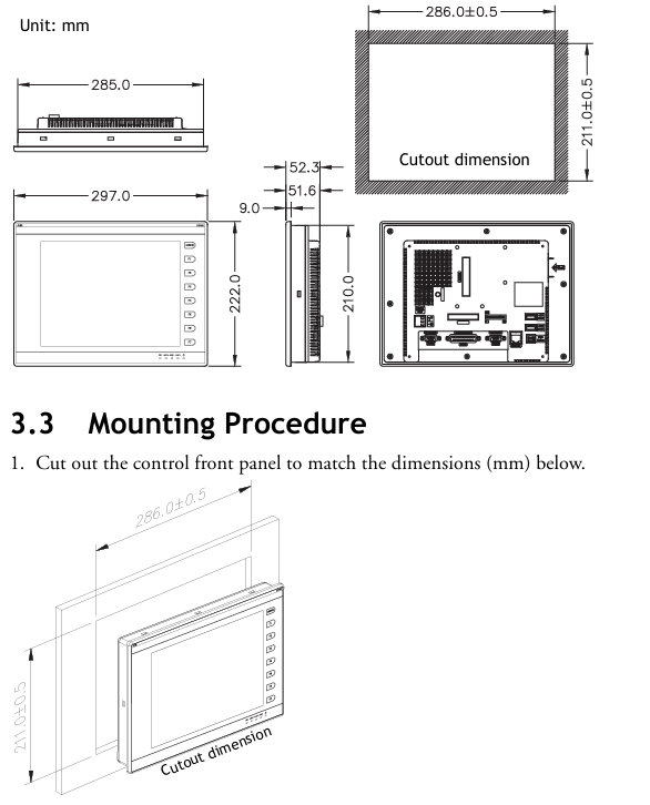
Panel perforation: Drill holes on the control front panel according to the size (286.0 ± 0.5mm × 211.0mm), ensuring that the edges are flat and free of burrs;
Equipment embedding: Insert CP450 into the opening and fix it to the front panel with the built-in fasteners (screws) of the equipment, with a torque controlled at 0.6~0.7 Nm (5.31~6.2 lb in), to avoid uneven force that may cause deformation of the equipment;
Installation angle: The installation angle of the equipment should be within the range of 0~135 ° (based on the display screen) to ensure the operating field of view and heat dissipation effect.
3. Grounding and power wiring
Grounding operation: Connect the grounding cable from the power connector on the rear panel of the device to an independent grounding point, ensuring that the grounding resistance is ≤ 100 Ω;
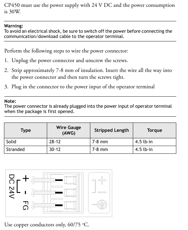
Power wiring: After disconnecting the power supply, remove the screw of the power connector, insert the stripped 24V DC wire (positive and negative poles distinguished), tighten the screw, and plug it back into the device power input interface. Copper conductors must be used and meet the wire diameter requirements (refer to safety specification 2.3).
4. Wiring requirements
Communication cables should be routed separately from power cables to avoid electromagnetic interference;
All communication cables must use shielded cables to reduce the impact of noise.
DIP switch configuration (core function switching)
The 12 bit DIP switches (SW1-SW12) on the rear panel of CP450 are used to configure working modes, communication parameters, password requirements, etc. The key switch functions are shown in the table below (switches not labeled as "reserved" must be strictly set according to requirements):
Specific setting instructions for DIP switch function classification
SW3~SW4 working mode - ON+ON: run user applications; -ON+OFF: Run the aging test program; -OFF+ON: Update BIOS; -OFF+OFF: Run the bench test program
SW5 communication parameter source - ON: communication parameters defined using the device configuration interface; -OFF: Communication parameters defined using CP400Soft software
SW6 power on password requirement - ON: After the power on self-test, the password needs to be entered; -OFF: No password required for startup
SW7 system menu display - ON: After self-test, the system menu is displayed; -OFF: Run the user application directly without displaying the system menu
SW8 default user level - ON: When starting up without a password, the default user level is 1 (highest privilege); -OFF: Default level 9 (minimum permission)
SW10 COM2 port mode - ON: COM2 is in RS485 mode; -OFF: COM2 is in RS422 mode
SW11 COM3 port mode - ON: COM3 is in RS485 mode; -OFF: COM3 is in RS422 mode
SW1,2,9,12 retain no functionality, no need to set
Communication port configuration
CP450 provides three serial communication ports (COM1~COM3), one Ethernet port, and one USB port, supporting flexible connections with controllers and third-party devices. The key parameters are as follows:
1. Serial communication ports (COM1~COM3)
Port interface type supports protocol pin function (core) adaptation scenarios
COM1 9-pin female head RS232/RS485- RS485+(1 pin), RS485- (6 pins); -RS232 RXD (2-pin), TXD (3-pin), GND (5-pin) are connected to controllers (such as PLCs) and simple peripherals
COM2 25 pin female head RS232/RS422/RS485- RS485+/RS422 TX+(14 pins), RS485-/RS422 TX - (15 pins); -RS232 TXD (2-pin), RXD (3-pin) for connecting multiple devices and long-distance communication
COM3 9-pin female head RS422/RS485- RS485+/RS422 TX+(1 pin), RS485-/RS422 TX - (6 pins); -RS422 RX+(4-pin), RX - (9-pin) long-distance, high stability communication
Attention: The port mode needs to be matched with the DIP switch (if COM2 is RS485, set SW10=ON), otherwise communication will fail.
2. Other communication interfaces
Ethernet port: only supported by CP450 T-ETH model, used for high-speed network communication, suitable for industrial Ethernet scenarios;
USB interface: 2 USB host ports (for connecting printers and USB drives for data storage or printing), 1 USB device port (for connecting to a PC to transfer applications or recipes);
CF card interface: used for extended storage, can store application backup, recipe data, etc.
Core operational functions (including debugging and maintenance)
1. Self Test
After the device is powered on, it automatically performs hardware self-test and the screen displays the test results. The following items should be focused on:
Key detection contents: RAM, battery status, BIOS checksum, firmware checksum, application checksum, communication ports (COM1~COM3), real-time clock (RTC);
Fault handling: If a certain item displays "Failed", follow the prompts to troubleshoot (such as firmware/application verification failure requiring re download; communication port failure requiring checking wiring and DIP switch);
- ABB
- General Electric
- EMERSON
- Honeywell
- HIMA
- ALSTOM
- Rolls-Royce
- MOTOROLA
- Rockwell
- Siemens
- Woodward
- YOKOGAWA
- FOXBORO
- KOLLMORGEN
- MOOG
- KB
- YAMAHA
- BENDER
- TEKTRONIX
- Westinghouse
- AMAT
- AB
- XYCOM
- Yaskawa
- B&R
- Schneider
- Kongsberg
- NI
- WATLOW
- ProSoft
- SEW
- ADVANCED
- Reliance
- TRICONEX
- METSO
- MAN
- Advantest
- STUDER
- KONGSBERG
- DANAHER MOTION
- Bently
- Galil
- EATON
- MOLEX
- DEIF
- B&W
- ZYGO
- Aerotech
- DANFOSS
- Beijer
- Moxa
- Rexroth
- Johnson
- WAGO
- TOSHIBA
- BMCM
- SMC
- HITACHI
- HIRSCHMANN
- Application field
- XP POWER
- CTI
- TRICON
- STOBER
- Thinklogical
- Horner Automation
- Meggitt
- Fanuc
- Baldor
- SHINKAWA


