
YOKOGAWA DLM3034HD/DLM3054HD High Definition Oscilloscope
YOKOGAWA DLM3034HD/DLM3054HD High Definition Oscilloscope
Overview
This document is a functional guide for YOKOGAWA DLM3034HD and DLM3054HD series high-definition oscilloscopes, aimed at helping users operate and fully utilize instrument functions correctly. The document contains core content such as instrument characteristics, operating methods, trigger settings, data processing, etc. It also provides global contact information, document revision information, and trademark statements. The first version was released in October 2024, and the content may change due to product performance upgrades. It is recommended to obtain the latest manual through the official website.
Core functional modules
1. Vertical axis setting (analog signal/logic signal)
(1) Analog signal (CH1-CH4)
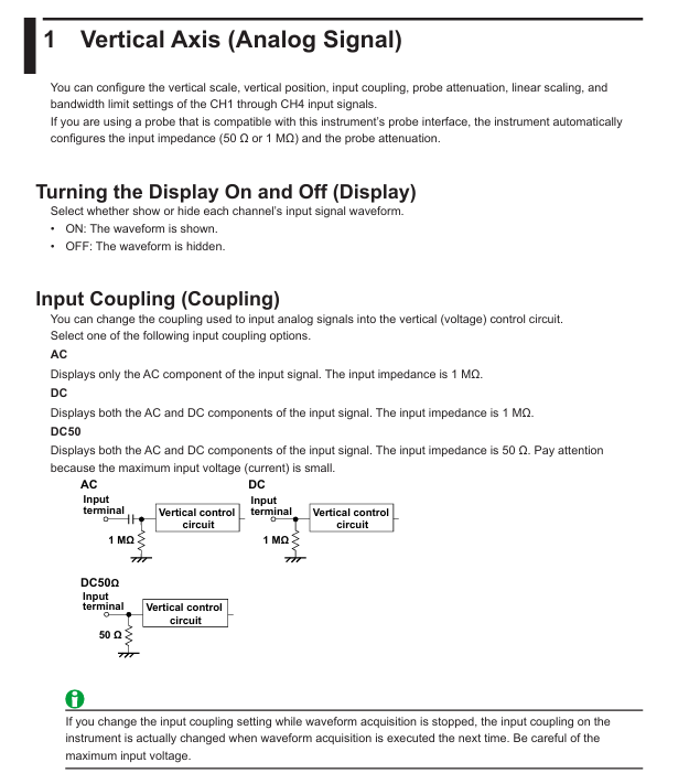
Input coupling: Supports AC (displaying only AC components, 1 M Ω impedance), DC (displaying AC/DC components, 1 M Ω impedance), DC50 (displaying AC/DC components, 50 Ω impedance, please note the maximum input voltage limit).
Probe attenuation: Voltage probes support attenuation ratios from 0.001:1 to 2000:1, while current probes support conversion ratios from 0.001 A: 1 V to 2000 A: 1 V. Probes compatible with probe interfaces can automatically configure input impedance and attenuation ratios.
Other functions: Supports waveform inversion display, linear scaling (formula:
Y=AX+B
, customizable units), bandwidth limit (FULL to 8 kHz multiple gears), offset adjustment (different range depending on coupling method and vertical scale), vertical scale (adjustable through SCALE knob, press to enter fine adjustment mode), and vertical position (adjustable with POSITION knob, range ± 4 grids).
(2) Logic signal (LOGIC)
Threshold setting: Preset CMOS (5V/3.3V/2.5V/1.8V), ECL and other standard thresholds, support user-defined, 701988 probe threshold range ± 40V, 701989 probe ± 6V.
Noise suppression: The 701989 probe can be set with a hysteresis of approximately 100mV or 250mV, while the 701988 probe has a fixed hysteresis of 80mV.
Bus display: Supports Bit0-Bit7 combination as bus signal, can choose binary (Bin) or hexadecimal (Hex) display, custom label (up to 8 characters).
Status display: Based on the sampling logic signal status of the clock source (CH1-CH3, LOGIC), it supports clock polarity and detection level settings.
2. Horizontal axis setting (timeline)
Time scale: adjustable through TIME/DIV knob, supports Roll Mode, suitable for observing low-frequency or slowly changing signals. At this time, the waveform flows from right to left without relying on triggering updates.
Sampling rate calculation: The formula is "Sampling rate=Record length/(time scale x 10 grids)", with a record length range of 1.25 kpoints to 1 Gpoints (depending on memory options), and different record lengths correspond to different historical waveform storage quantities.
3. Trigger function
(1) Trigger mode
Pattern description
If triggered within Auto timeout (approximately 100ms or 10 grid times, whichever is greater), the waveform will be updated. Otherwise, it will be automatically updated and supports scrolling mode
Auto Level trigger logic is similar to Auto, automatically adjusting the trigger level to the center value of the trigger source amplitude when there is no trigger (only CH1-CH4 is valid)
Normal updates waveform only when triggering conditions are met
After N Single meets the triggering conditions, continuously collect the specified number of waveforms, and display them after completion
Update the waveform once and stop collecting after triggering Single
(2) Trigger type
EDGE (Edge Triggering): Based on a single trigger source for rising/falling/dual edge triggering, it supports settings such as trigger level, slope, delay, and hold time.
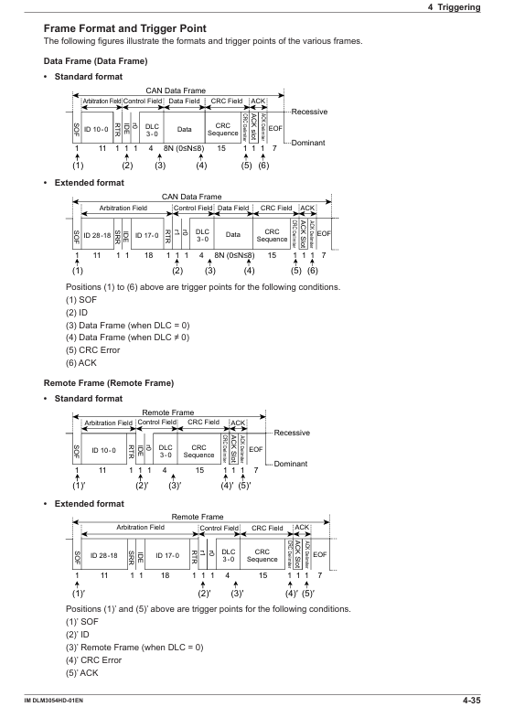
Enhanced Trigger: Contains multiple complex trigger types, such as edge or trigger, mode trigger, pulse width trigger (based on the relationship between pulse width and reference time), rise/fall time trigger, timeout trigger, window trigger, serial bus trigger (FlexRay/CAN FD/LIN/CXPI, mostly option functions), TV trigger (NTSC/PAL/SDTV/HDTV, etc.).
Trigger combination: Supports triggering A (EDGE/ENHANCED) and triggering B (B TRIG) combinations, such as A delaying B (detecting B triggering after a specified time after A triggering), A to B (N times) (detecting B triggering N times after A triggering).
(3) Key trigger parameters
Trigger level: Analog signal range ± 8 grids (resolution 0.01 grids), logic signal varies with probe model (701988 ± 40V, 701989 ± 6V).
Noise suppression: Analog signals support 0.3/0.5/1 grid hysteresis, and logic signals have different hysteresis options depending on the probe model.
Trigger delay: Range - (post trigger time) to 10 seconds, supports delay cancellation (whether to apply delay to time measurement).
4. Waveform acquisition
Acquisition modes: Normal (no processing display), Envelope (display maximum/minimum value pairs to avoid aliasing), Average (multiple acquisition average denoising, supports exponential/linear averaging, average frequency 2-1024).
High resolution mode: After activation, the effective bit count is extended to 16 bits through digital and bandwidth filtering (not applicable to logical signals).
Sampling modes: real-time sampling (maximum 2.5 GS/s), interpolation mode (sinx/x interpolation, suitable for single signal), repeated sampling (random sampling, suitable for repeated signals, equivalent sampling rate up to 250 GS/s).
Acquisition control: RUN/STOP (continuous acquisition/stop), SINGLE (single acquisition), supporting record length settings (affecting acquisition memory usage and historical waveform count).
5. Display function
Window types: including main window (Main), zoom window (Zoom1/Zoom 2), XY window (XY1/XY2), FFT window, trend/histogram window, supporting multi window segmentation (Single/Dual/Triad/Quad formats, etc.).
Display settings: Supports waveform interpolation (OFF/Sine/Linear/Pulse), grid type (point grid/line grid/frame/crosshair), waveform intensity (1-64 levels), cumulative display (displays waveform frequency by intensity/color, cumulative time 100ms-100s or infinite).
XY waveform display: Map two signals to the X-axis and Y-axis respectively, observe signal correlation, support cursor measurement and area calculation (such as safe working area SOA analysis).
6. Data processing and analysis
(1) Calculation and reference waveform
Calculation mode: Supports Math (based on source waveform calculation) and Ref (displaying reference waveform), with calculation sources available from CH1-CH4 and Math1-Math3. Supports addition, subtraction, multiplication, division, filtering, integration, counting, and other operations, with user-defined calculations (option function, supports 128 character expressions).
Reference waveform: It can load screen display waveforms or historical saved waveforms, and supports vertical position adjustment and measurement analysis.
(2) FFT analysis
Function enabled: Supports FFT1/FFT2, allows selection of analysis sources (CH1-CH4, Math1-Math4), and sets spectrum types (power spectrum, linear spectrum, etc., depending on whether there are user-defined options).
Parameter settings: time window (rectangle/Hanning/Flattop), FFT point count (1.25k-1.25M), analysis range (Main/Zoom1/Zoom2), scale settings (automatic/manual), supports cursor measurement and peak detection.
(3) Cursor measurement
Cursor mode: Δ T (time difference), Δ V (voltage difference), Δ T&Δ V (time voltage combination), Marker (4 marker points), Angle (angle measurement), supports multi-channel measurement (CH1-CH4, LOGIC, Math1-Math4).
Measurement items: time (T1/T2/Δ T/1/Δ T), voltage (V1/V2/Δ V), angle (D1/D2/Δ D), supports cursor jumping (such as jumping to the center of the zoom window).
(4) Automatic parameter measurement
Measurement items: voltage parameters (maximum/minimum/peak to peak/effective value, etc.), time parameters (frequency/cycle/pulse width/duty cycle, etc.), delay measurement (multi-channel delay), supporting statistical analysis (maximum/minimum/average/standard deviation/count).
Measurement settings: Select the measurement window (Main/Zoom1/Zoom2), measurement time period (T Range1/T Range2), reference level (percentage or absolute value), and support cycle mode (measured by signal cycle).
(5) Waveform Search and Serial Bus Analysis
Waveform search: supports search types such as edge, mode, pulse width, timeout, etc., sets search sources and conditions (such as level, polarity, time range), displays detection results, and scales positioning.
Serial bus analysis: Supports FlexRay/CAN/CAN FD/LIN/CXPI/SENT/PSI5 Airbag/UART/I2C/SPI buses (mostly options), can decode frame/field information, display results in lists, trend analysis and search, supports symbol display (requires loading. sbl files).
(6) Histogram display
Function enabled: Supports Historam1/Historam2, select the source waveform (CH1-CH4, Math1-Math4) and statistical axis (vertical/horizontal), and set the statistical range (Main/Zoom1/Zoom2).
Measurement items: peak value, maximum value, minimum value, mean value, standard deviation, median, proportion within the range of ± 1 σ/± 2 σ/± 3 σ, supporting cursor measurement.
(7) Power analysis (option function)
Switching Loss Analysis (SW Loss): measures the total loss and switching loss of the device, supports different loss types (U × I, RDS (on) × I ², VCE (sat) × I), and sets voltage/current levels and reference levels.
Safe working area analysis (SOA): X-axis voltage, Y-axis current, plot device operating range, evaluate whether it is within the safe area.
Harmonic analysis: Complies with IEC standards, analyzes up to the 40th harmonic, supports Class A-D classification, calculates harmonic current and compares it with limit values, and displays the results in a list and bar chart.
Joule integral (I ² t): Joule integral for measuring surge current, used for fuse evaluation, supporting waveform display and statistical analysis.
Power measurement: Simultaneously measure the power of two circuits, calculate voltage/current/power parameters (active/reactive/apparent power, power factor, etc.), support probe de skewing and statistical analysis.
7. Historical waveform management
Display mode: Supports single waveform (One), all overlay (All), and accumulate display. It can highlight the specified record number waveform and set the display range (Start/End No.).
Search function: Based on rectangular area, waveform area, polygon area or parameter setting search conditions, supports AND/OR logic, and displays a list of detected waveforms and timestamps.
Playback function: Play back historical waveforms at a specified speed (x1/60 to x10), supporting playback starting from the earliest/latest waveform.
8. Data storage and output
(1) Printing and screen saving
Output target: Built in printer (option), USB printer, network printer, file (PNG/BMP/JPEG format), supports simultaneous output of multiple targets (Multi mode).
Print settings: Print mode (with/without menu), color (color/black and white/grayscale), whether to include setting information, file saving supports automatic naming (serial number/date) and custom file name.
(2) Data saving and loading
Save data types: waveform data (binary/ASCII/ASCII with time information), set data (saved to file or internal memory # 1- # 3), screen image, waveform area data, snapshot data, automatic measurement data, serial bus analysis results, FFT data, histogram data, timestamp list.
Storage devices: internal storage (Flash_Sem), USB storage devices, network drives, supporting file renaming, copying, protection settings, loading data supports waveform, settings, waveform area and other types.
9. Other functions
System settings: AUTO SETUP, DEFILT SETUP, SNAP SHOT to save current waveform, Calibration, Remote Control, system configuration (such as touch screen settings).
Network functions: Supports TCP/IP, FTP server, email sending (sending email notifications when triggered), network drive, network printer, SNTP time synchronization.
Synchronization operation (DLMsync, option): Supports multiple oscilloscopes to work synchronously, expand channels, or increase sampling rates.
Precautions
Safe operation: In DC50 coupling mode, the input impedance is 50 Ω and the maximum input voltage is small, so caution should be exercised during operation; The demagnetization and zeroing of the current probe require disconnecting the conductor to avoid damaging the equipment.
Performance limitations: Long record lengths may result in slower calculation and measurement speeds; Partial functions (such as serial bus triggering and user-defined calculations) are optional and require confirmation of instrument configuration.
Data management: When automatically naming files, attention should be paid to the storage device format (FAT16/FAT32/exFAT) to limit the number of files and avoid duplicate file names causing save failures.
Software compatibility: The Yokogawa IS8000 software can be used to analyze waveforms on a PC, which needs to be obtained through the official website; CANdb files need to be converted to. sbl files in order to be used for symbol display.
- OMRON
- ABB
- General Electric
- EMERSON
- Honeywell
- HIMA
- ALSTOM
- Rolls-Royce
- MOTOROLA
- Rockwell
- Siemens
- Woodward
- YOKOGAWA
- FOXBORO
- KOLLMORGEN
- MOOG
- KB
- YAMAHA
- BENDER
- TEKTRONIX
- Westinghouse
- AMAT
- AB
- XYCOM
- Yaskawa
- B&R
- Schneider
- KONGSBERG
- NI
- WATLOW
- ProSoft
- SEW
- ADVANCED
- Reliance
- TRICONEX
- METSO
- MAN
- Advantest
- STUDER
- DANAHER MOTION
- Bently
- Galil
- EATON
- MOLEX
- DEIF
- B&W
- ZYGO
- Aerotech
- DANFOSS
- Beijer
- Moxa
- Rexroth
- Johnson
- WAGO
- TOSHIBA
- BMCM
- SMC
- HITACHI
- HIRSCHMANN
- Application field
- XP POWER
- CTI
- TRICON
- STOBER
- Thinklogical
- Horner Automation
- Meggitt
- Fanuc
- Baldor
- SHINKAWA
- Other Brands
- UniOP
- KUKA
- Iba
- Beckhoff
-
 Basler D90 96801 100 PCB Card
 -
 Basler XR2002F Voltage Regulator (110 VAC, 48-480 Hz)
 -
 Basler SR8A-2B14B3A Regulator
 -
 Basler 9561500100 Module
 -
 Basler DECS-400 BE1-11 System
 -
 Basler DECS-100-B15 Excitation Control
 -
 Basler SCP 210 Frequency Controller
 -
 Basler SR4A-2B15B3A Static Voltage Regulator
 -
 Basler BE1-32R Power Relay
 -
 Basler PIA2400-17GM Power Interface Adapter
 -
 Basler MVC 232 Manual Voltage Control Module
 -
 Basler SSR 32-12 Static Voltage Regulator
 -
 Basler 5MW AVR Generator Voltage Regulator
 -
 Basler VR63-4B Voltage Regulator
 -
 Basler DECS-100-A05 AVR for Engine Generator
 -
 Basler DECS-100-B15 Automatic Voltage Regulator
 -
 Basler BE1-32R Directional Power Relay
 -
 Basler BE1-87B Differential Relay
 -
 Basler UFOV 260A Protective Module
 -
 Basler 9-2614-02-100 PCB Rev M
 -
Basler DECS-100-B15 Digital AVR
-
 Basler 9284900103 PS DECS-400N
 -
 Basler D4N3H1U Intertie Protection
 -
 Basler DECS-100-B15 A15 AVR
 -
 Basler KR4F Voltage Regulator
 -
 Basler BE26434 T14 Transformer
 -
 Basler SR8A-2B15B3A Regulator
 -
 Westinghouse 774B472A12 AR Relay
 -
Basler DECS-100-B15 AVR
-
Basler XR2002F Regulator 110V
-
Basler SR125-E Static Regulator
-
 Basler SSR 125-12 Regulator
 -
 Basler MOC2599 Motor Pot
 -
 Basler BE1-DFPR Feeder Relay
 -
 Basler CBS 305 Current Boost
 -
 Basler BE1-25 AutoSync
 -
 Basler MVC 300 Voltage Control
 -
 Basler BE3-25A AutoSync
 -
 Basler KR7FF Static Regulator
 -
 Basler 90-49000-100 Regulator
 -
 Basler 880 kVA Dry Type Transformer Specs
 -
 Basler Electric BE1-25 Sync-Check Relay Specs
 -
 Basler SSR 125-12 Voltage Regulator Specs
 -
 Basler Electric BE1-851 Overcurrent Relay Review
 -
Basler Electric 149D930G02 Control Sub-Assembly
-
 Basler Electric BE1-81O/UT Frequency Relay Specs
 -
 Basler Electric BE1-51/27C Overcurrent Relay
 -
 Basler Electric 149D956G02 Industrial Component
 -
Basler Electric BE1-51A Overcurrent Relay Specs
-
 Basler Electric BE1-40Q Loss of Excitation Relay
 -
 Basler DECS-200 Excitation Control System
 -
 Basler DECS-200 Voltage Regulator 56-277V AC / 125V DC
 -
Basler BE1-87T Transformer Differential Relay
-
 Basler RDP-110-S1 Protection Relay
 -
 Basler BE1-700V Digital Protective Relay
 -
 Basler BE1-951 Overcurrent Protection System
 -
 Basler DECS-300 Digital Excitation Control
 -
 Basler DECS-200 Digital Excitation Control
 -
 Basler DECS-200-1C Excitation Control System
 -
Basler DECS-200-1L Digital Excitation Control
-
 Basler Electric BE1-GPS Generator Protection System
 -
Basler Electric DECS-200-1C Digital Excitation Controller
-
 Basler Electric DECS125-15 Excitation Control with Power Module
 -
 Basler Electric BE1-87G Differential Relay
 -
 Basler Electric BE1-11 Protection System I5A3M2P2N0EA00
 -
Basler Electric DECS-200-1C Excitation Control System
-
Basler Electric BE1-11g Generator Protection Relay
-
Basler Electric DECS 125-15-B2C1 V2.0.9 Excitation Control
-
 Basler Electric BE1-81O/UT3ED1JA7N2F Frequency Relay
 -
Basler Electric BE1-81O/UT3EE1YB7N1F Frequency Relay
-
 Basler Electric DECS-200-1L Digital Excitation Control System
 -
Basler DECS125-15-B2C1 Excitation Control
-
 Basler 9507900205 SSR Retrofit Voltage Regulator
 -
 Basler BE2000E Digital Voltage Regulator
 -
 Basler BE1-GPS Generator Protection System
 -
Basler DECS-250-CN1CN1N Digital Excitation Control
-
 Basler DGC-2020 Genset Controller
 -
 Basler BE1-81O UT3ED1LA7N0F Frequency Relay (Variant)
 -
 Basler BE1-81O UT3EE1YA9S0F Frequency Relay (Variant)
 -
Basler BE1-81O Over/Under Frequency Relay
-
Basler DECS125-15 Digital Excitation Control
-
Basler Electric BE1-951 Overcurrent Protection System
-
 Basler Electric BE1-700V Digital Protective Relay
 -
 Basler Electric APR63-5 Automatic Voltage Regulator
 -
Basler Electric BE1-851 Overcurrent Protection System
-
Basler Electric DECS-250-LN1SN1N Excitation Control
-
 Basler Electric BE1-87T Transformer Differential Relay
 -
Basler Electric DECS-200-1L Excitation Control System
-
 Basler Electric 9310300100 DECS-300 Excitation Control
 -
 Basler Electric SSE-N 125-4.5KW Shunt Exciter Regulator
 -
 Basler Electric DGC-2020HD-5NS1DNSBA Genset Controller
 -
Basler Electric BE1-81-O/UT3EE1JB7N1F Frequency Relay
-
Basler Electric BE1-81T1EE1WA0N1F Frequency Relay
-
 Basler Electric BE1-25M1EA6PN5R1F Sync-Check Relay
 -
 Basler Electric BE1-GPS Generator Protection System
 -
Basler Electric DECS-250-LN1SN1N Excitation Control Rev V
-
 Basler Electric DECS-250-CN2CN1N Excitation Control
 -
Basler Electric BE1-50/51B-207 Overcurrent Relay
-
Basler Electric DECS-300-C0N0 Excitation Control System
-
Basler Electric DECS-200 Digital Excitation Control System
-
Basler Electric DECS-250-LN1CN1N Excitation Unit
-
Basler Electric DECS-250 LN2SA1D Excitation Unit Specs
-
Basler Electric BE1-87T Transformer Relay Review
-
Basler Electric BE1-11 Protection System
-
Basler Electric BE1-GPS100-E4N1H1N Protection System
-
 Allen-Bradley 442G-MABH-R Safety Module
 -
 Beckhoff CX1030-0111 PLC Assembly Profile
 -
 FANUC IC693CPU364 PLC Module
 -
 Orange Denmark Type 200816 220 PLC Specs
 -
 OMRON C200H-SNT31 Sysmac PLC Module
 -
 Allen Bradley 20AB022A3AYNANC0 PowerFlex 70
 -
 OMRON C200HW-PCU01 Position Control Unit
 -
 ABB AO845A-eA Analog Output Module
 -
 OMRON CJ1M-CPU22 CPU Unit
 -
 Allen Bradley 100-E265ED11 Contactor
 -
 Honeywell 51304511-100 Interface Module
 -
 SOLEXY BXF3S0101N0018 Gateway Module
 -
 OMRON CJ2H-CPU65 CPU Unit
 -
 Automation Direct GS2-45P0 AC Drive
 -
 M68-2000 2-Axis Motion CNC Controller
 -
 OMRON CJ1M-CPU11 V3.0 PLC CPU Unit
 -
 OMRON CJ1W-NC413 4-Axis Positioning Controller
 -
 OMRON 3G2A3-PRO16 Programming Console HMI
 -
 Siemens 3VT8440-2AA04-2GA2 Molded Case Circuit Breaker
 -
 Siemens 3RT5045 Contactor Series
 -
 OMRON C200HS-CPU01-E SYSMAC PLC Controller
 -
 OMRON C500-NC103-E Positioning Control Unit
 -
 OMRON CJ1W-TC001 Temperature Control Unit


