YOKOGAWA DLM3034HD/DLM3054HD High Definition Oscilloscope
YOKOGAWA DLM3034HD/DLM3054HD High Definition Oscilloscope
Overview
This document is a functional guide for YOKOGAWA DLM3034HD and DLM3054HD series high-definition oscilloscopes, aimed at helping users operate and fully utilize instrument functions correctly. The document contains core content such as instrument characteristics, operating methods, trigger settings, data processing, etc. It also provides global contact information, document revision information, and trademark statements. The first version was released in October 2024, and the content may change due to product performance upgrades. It is recommended to obtain the latest manual through the official website.
Core functional modules
1. Vertical axis setting (analog signal/logic signal)
(1) Analog signal (CH1-CH4)
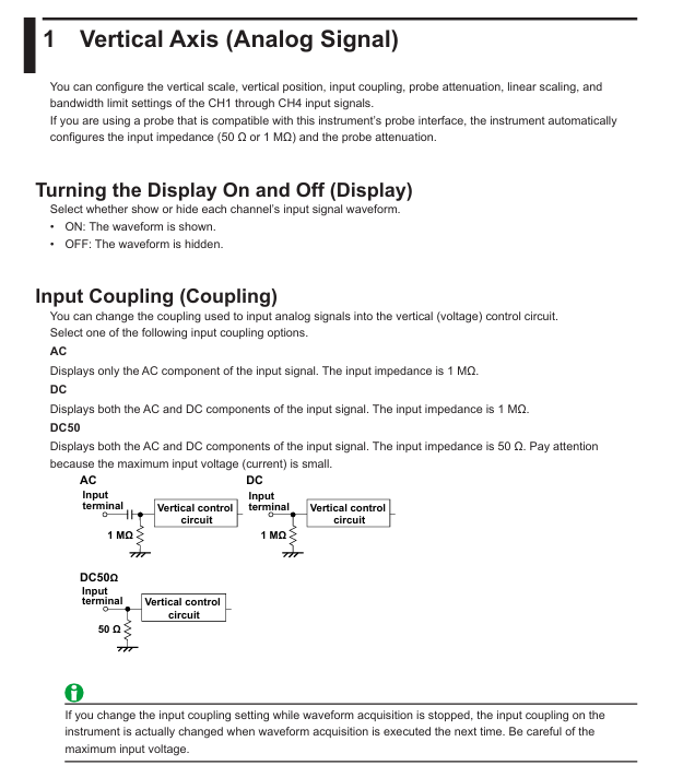
Input coupling: Supports AC (displaying only AC components, 1 M Ω impedance), DC (displaying AC/DC components, 1 M Ω impedance), DC50 (displaying AC/DC components, 50 Ω impedance, please note the maximum input voltage limit).
Probe attenuation: Voltage probes support attenuation ratios from 0.001:1 to 2000:1, while current probes support conversion ratios from 0.001 A: 1 V to 2000 A: 1 V. Probes compatible with probe interfaces can automatically configure input impedance and attenuation ratios.
Other functions: Supports waveform inversion display, linear scaling (formula:
Y=AX+B
, customizable units), bandwidth limit (FULL to 8 kHz multiple gears), offset adjustment (different range depending on coupling method and vertical scale), vertical scale (adjustable through SCALE knob, press to enter fine adjustment mode), and vertical position (adjustable with POSITION knob, range ± 4 grids).
(2) Logic signal (LOGIC)
Threshold setting: Preset CMOS (5V/3.3V/2.5V/1.8V), ECL and other standard thresholds, support user-defined, 701988 probe threshold range ± 40V, 701989 probe ± 6V.
Noise suppression: The 701989 probe can be set with a hysteresis of approximately 100mV or 250mV, while the 701988 probe has a fixed hysteresis of 80mV.
Bus display: Supports Bit0-Bit7 combination as bus signal, can choose binary (Bin) or hexadecimal (Hex) display, custom label (up to 8 characters).
Status display: Based on the sampling logic signal status of the clock source (CH1-CH3, LOGIC), it supports clock polarity and detection level settings.
2. Horizontal axis setting (timeline)
Time scale: adjustable through TIME/DIV knob, supports Roll Mode, suitable for observing low-frequency or slowly changing signals. At this time, the waveform flows from right to left without relying on triggering updates.
Sampling rate calculation: The formula is "Sampling rate=Record length/(time scale x 10 grids)", with a record length range of 1.25 kpoints to 1 Gpoints (depending on memory options), and different record lengths correspond to different historical waveform storage quantities.

3. Trigger function
(1) Trigger mode
Pattern description
If triggered within Auto timeout (approximately 100ms or 10 grid times, whichever is greater), the waveform will be updated. Otherwise, it will be automatically updated and supports scrolling mode
Auto Level trigger logic is similar to Auto, automatically adjusting the trigger level to the center value of the trigger source amplitude when there is no trigger (only CH1-CH4 is valid)
Normal updates waveform only when triggering conditions are met
After N Single meets the triggering conditions, continuously collect the specified number of waveforms, and display them after completion
Update the waveform once and stop collecting after triggering Single
(2) Trigger type
EDGE (Edge Triggering): Based on a single trigger source for rising/falling/dual edge triggering, it supports settings such as trigger level, slope, delay, and hold time.
Enhanced Trigger: Contains multiple complex trigger types, such as edge or trigger, mode trigger, pulse width trigger (based on the relationship between pulse width and reference time), rise/fall time trigger, timeout trigger, window trigger, serial bus trigger (FlexRay/CAN FD/LIN/CXPI, mostly option functions), TV trigger (NTSC/PAL/SDTV/HDTV, etc.).
Trigger combination: Supports triggering A (EDGE/ENHANCED) and triggering B (B TRIG) combinations, such as A delaying B (detecting B triggering after a specified time after A triggering), A to B (N times) (detecting B triggering N times after A triggering).
(3) Key trigger parameters
Trigger level: Analog signal range ± 8 grids (resolution 0.01 grids), logic signal varies with probe model (701988 ± 40V, 701989 ± 6V).
Noise suppression: Analog signals support 0.3/0.5/1 grid hysteresis, and logic signals have different hysteresis options depending on the probe model.
Trigger delay: Range - (post trigger time) to 10 seconds, supports delay cancellation (whether to apply delay to time measurement).
4. Waveform acquisition
Acquisition modes: Normal (no processing display), Envelope (display maximum/minimum value pairs to avoid aliasing), Average (multiple acquisition average denoising, supports exponential/linear averaging, average frequency 2-1024).
High resolution mode: After activation, the effective bit count is extended to 16 bits through digital and bandwidth filtering (not applicable to logical signals).
- ABB
- General Electric
- EMERSON
- Honeywell
- HIMA
- ALSTOM
- Rolls-Royce
- MOTOROLA
- Rockwell
- Siemens
- Woodward
- YOKOGAWA
- FOXBORO
- KOLLMORGEN
- MOOG
- KB
- YAMAHA
- BENDER
- TEKTRONIX
- Westinghouse
- AMAT
- AB
- XYCOM
- Yaskawa
- B&R
- Schneider
- Kongsberg
- NI
- WATLOW
- ProSoft
- SEW
- ADVANCED
- Reliance
- TRICONEX
- METSO
- MAN
- Advantest
- STUDER
- KONGSBERG
- DANAHER MOTION
- Bently
- Galil
- EATON
- MOLEX
- DEIF
- B&W
- ZYGO
- Aerotech
- DANFOSS
- Beijer
- Moxa
- Rexroth
- Johnson
- WAGO
- TOSHIBA
- BMCM
- SMC
- HITACHI
- HIRSCHMANN
- Application field
- XP POWER
- CTI
- TRICON
- STOBER
- Thinklogical
- Horner Automation
- Meggitt
- Fanuc
- Baldor
- SHINKAWA
- Other Brands


