YOKOGAWA WT1801R series precision power analyzer communication interface
YOKOGAWA WT1801R series precision power analyzer communication interface
Overview
The communication interface user guide for YOKOGAWA WT1801R, WT1802R, WT1803R, WT1804R, WT1805R, and WT1806R series precision power analyzers was first released in October 2024. The core of the document revolves around the three communication interfaces of the instrument (Ethernet, USB, GP-IB), providing detailed explanations of interface functions, configuration methods, programming instructions, and status reporting mechanisms. It also provides a document system, terminology conventions, and global contact information, aiming to help users achieve remote control and data exchange of the instrument through PC.
Core Communication Interface Functions and Configuration
1. Ethernet interface
(1) Core Features and Specifications
Compatibility: Compliant with IEEE 802.3 standard and supports TCP/IP (VXI-11) communication protocol.
Connection capability: Supports connection with PC through hub/router, does not support cross line direct connection; The maximum number of simultaneous connections is limited by network devices.
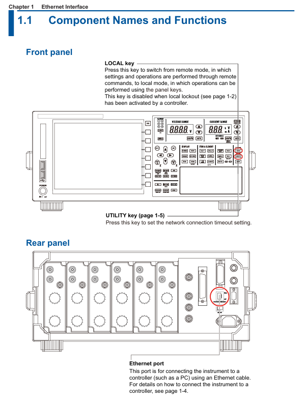
Remote control switch: Receive: Communicate: REMote ON/OFF command to switch between remote/local mode. In remote mode, only the LOCAL key is available (disabled when local is locked).
Timeout setting: The network connection timeout time can be set (1-3600 seconds or "infinite"), and the connection will be automatically disconnected after timeout. The default is "infinite".
(2) Configuration steps
Hardware connection: Use shielded twisted pair (STP) to connect the Ethernet port of the instrument Rear panel to the hub/router.
Enter the configuration menu: Press the UTIL key on the panel → click the Remote Control soft key → select the Network soft key to enter the network settings interface.
TCP/IP settings: IP address, subnet mask, and default gateway need to be configured (refer to section 20.2 of the IM WT1801R-02EN user manual for detailed steps).
Timeout setting: In the network settings interface, adjust the timeout time (Infinite or 1-3600s) through the cursor keys.
2. USB interface (USB-TMC)
(1) Core Features and Specifications
Compatibility: Compliant with USB 3.0 standard, supports USB-TMC (Test Measurement Class) protocol, requires installation of Yokogawa dedicated USB driver.
System requirements: Only supports Windows 10/11 system, PC needs to install communication library (TMCTL) and USB device driver (official website) https://tmi.yokogawa.com/ Downloadable).
Remote mode switching: Consistent with the Ethernet interface logic, it can be switched using the COMMunicate command or LOCAL key, and supports local locking.
Uniqueness: Only one USB device connection is supported at a time and cannot be used simultaneously with Ethernet or GP-IB interfaces.
(2) Configuration steps
Hardware connection: Connect the USB port of the instrument Rear panel to the PC using a USB Type B cable, and wait for 20-30 seconds after booting up before operating (to avoid damaging the device).
Driver installation: Download and install the Yokogawa USB TMC driver from the official website, and prohibit the use of third-party drivers.
View device serial number: Press the UTIL key → click on the Remote Control soft key → select the USB soft key to view the device serial number required for USB-TMC communication.
3. GP-IB interface (IEEE 488)
(1) Core Features and Specifications
Compatibility: Compliant with IEEE 488-1978 (Mechanical/Electrical) and IEEE 488.2-1992 (Protocol) standards, supports National Instruments GP-IB cards (such as PCIe GPIB, GPIB-UB-HS+).
Functional subset: Supports SH1 (source handshake), AH1 (receive handshake), T6 (basic talker), L4 (basic listener), SR1 (service request) and other functional subsets, without controller capability.
Address setting: The address range is 0-30, and each device on the bus needs to be assigned a unique address to avoid conflicts.
Connection restriction: The bus can connect up to 15 devices (including controllers), with a single cable length of ≤ 2 meters and a total length of ≤ 20 meters.
(2) Configuration steps
Hardware connection: In the shutdown state, use a 24 pin GP-IB cable to connect the GP-IB port of the instrument Rear panel to the GP-IB board of the PC, and tighten the connector screws.
Address configuration: Press the UTIL key → click the Remote Control soft key → select the GP-IB soft key, and set the address (0-30).
Interface response: Supports interface messages such as IFC (interface clearing), REN (remote enable), SDC (selected device clearing), etc. Please refer to section 3.5 of the document for specific response logic.

Fundamentals of Programming and Instruction System
1. Core programming concepts
Message types: divided into "program messages" (instructions sent by the PC to the instrument, such as configuration instructions and query instructions) and "response messages" (data returned by the instrument to the PC, such as measurement results and status information).
Instruction structure:
Common instruction: IEEE 488.2 standard instruction, starting with * (such as * CLS clearing status register, * IDN?)? Check the instrument model).
- ABB
- General Electric
- EMERSON
- Honeywell
- HIMA
- ALSTOM
- Rolls-Royce
- MOTOROLA
- Rockwell
- Siemens
- Woodward
- YOKOGAWA
- FOXBORO
- KOLLMORGEN
- MOOG
- KB
- YAMAHA
- BENDER
- TEKTRONIX
- Westinghouse
- AMAT
- AB
- XYCOM
- Yaskawa
- B&R
- Schneider
- Kongsberg
- NI
- WATLOW
- ProSoft
- SEW
- ADVANCED
- Reliance
- TRICONEX
- METSO
- MAN
- Advantest
- STUDER
- KONGSBERG
- DANAHER MOTION
- Bently
- Galil
- EATON
- MOLEX
- DEIF
- B&W
- ZYGO
- Aerotech
- DANFOSS
- Beijer
- Moxa
- Rexroth
- Johnson
- WAGO
- TOSHIBA
- BMCM
- SMC
- HITACHI
- HIRSCHMANN
- Application field
- XP POWER
- CTI
- TRICON
- STOBER
- Thinklogical
- Horner Automation
- Meggitt
- Fanuc
- Baldor
- SHINKAWA
- Other Brands


