
ABB Digitic 500 Industrial Controller
ABB Digitic 500 Industrial Controller
Product overview
The Digitic 500 is a compact industrial controller suitable for single control loop instrumentation to small and medium-sized process automation, capable of completing simple to complex control tasks. Its documentation system includes installation manuals, debugging manuals, operation manuals, etc., and interface instructions (such as MODBUS) can also be provided upon request.
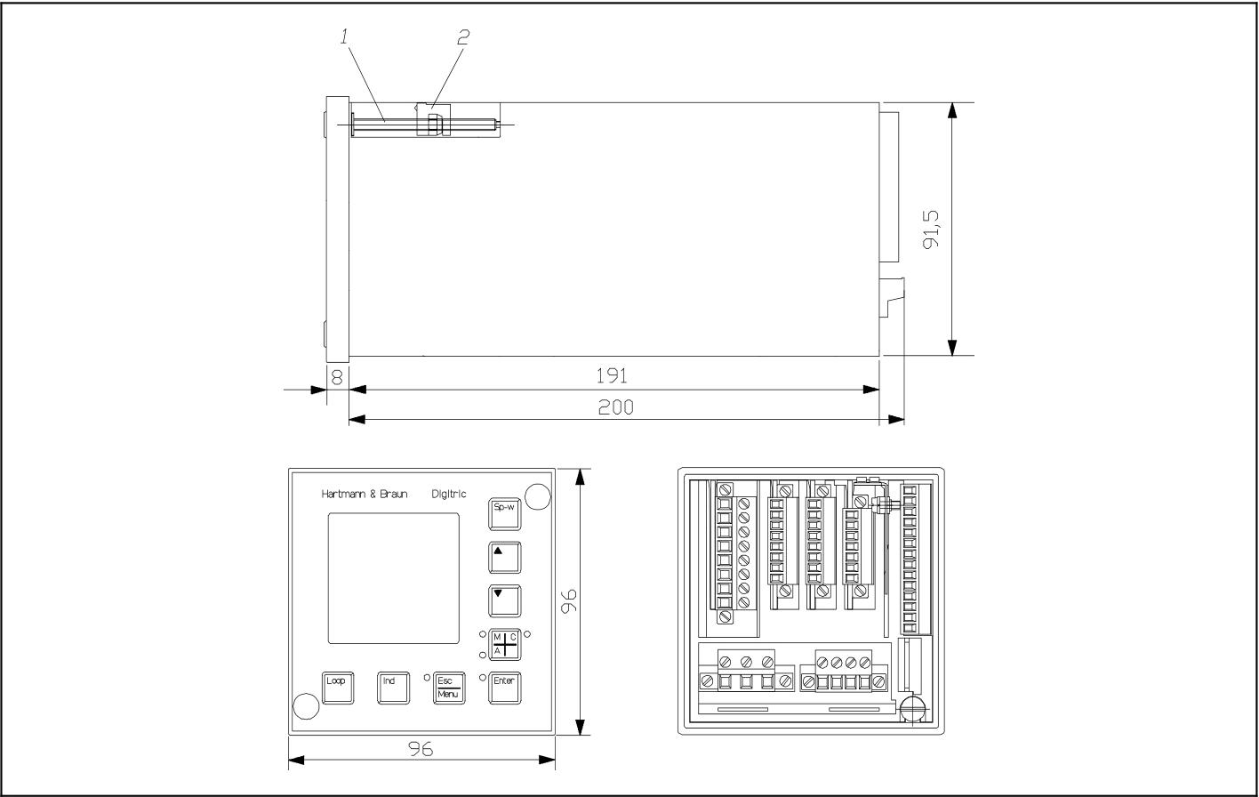
Basic configuration and functions
Basic version: Includes 1 universal input (supporting signals such as thermocouples, Pt100, transmitters, etc., with built-in standard sensor linearization table), 1 mA input (can be used as feedforward or setpoint input, and position feedback in stepper controllers), 1 mA output (for positioning signals, etc.), 2 configurable binary inputs/outputs, 2 relays (for executing signals, alarm outputs, etc.), and 4 module slots for expanding functions.
Programmer: Each controller includes a configurable programmer that can preset time related settings, store up to 10 programs, and each program contains 15 segments.
Controller output types: including two-point PID control, hot off cold control, step control, continuous control (optional split range output), etc.
Parameters and Configuration: Parameter settings require entering the password protected parameter level through the menu key; The configuration methods include list configuration (selecting standard functions from the built-in list of the device, which can be operated through IBISRR computer program) and free configuration (allowing customers to specific configurations, which can be added with logic control through the function plan editor).
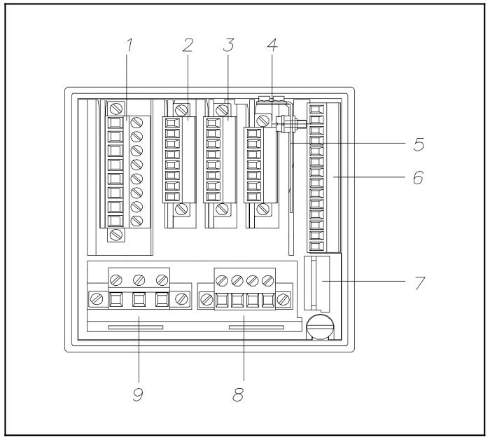
Installation process
Model identification: Identify the model through the side nameplate.
Installation location: Suitable for front installation in control rooms, control cabinets, and machines, ensuring that it does not exceed the climate and mechanical capacity limits specified in the "Technical Data".
Installation steps:
Panel opening: It must comply with DIN 43700 standard, with dimensions of 92+0.8mm × 92+0.8mm. When installed horizontally and tightly, the strip width should be at least 10mm, and at least 40mm ventilation space should be reserved above and below.
Fixed equipment: Remove the front panel dust cover, rotate the clamping claw screw counterclockwise until the clamping claw can be inserted into the panel, push the module into the panel opening, then rotate the screw clockwise to fix it, and finally reinstall the dust cover.
Connection instructions
Signal connection (basic model): using plug-in screw terminals, supporting solid or multi strand wires (maximum wire cross-section of 1.5mm ², maximum relay of 2.5mm ²), including interfaces for power connection, analog input/output, binary input/output, relay output, etc., with relay output up to 250V AC, 1A (cos φ=0.9).
Module and computer connection: The backend includes shielded terminal boards, basic model signal connections, computer ports (configuration interfaces), relay outputs, power supply, and other interfaces.
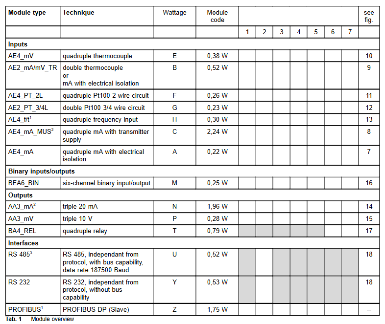
Module type and configuration
Available modules: including various analog input modules (such as 4 x mA, 2 x mA/thermocouple/mV, 4 x thermocouple, 4 x Pt100, etc.), binary input/output modules (6 channels), analog output modules (3 x mA, 3 x V), digital output modules (4 x relays), interface modules (RS-485, RS-232, PROFIBUS DP slave), etc., with a total of 4 module slots. There are no fixed slot restrictions for module allocation except for interfaces and relays.
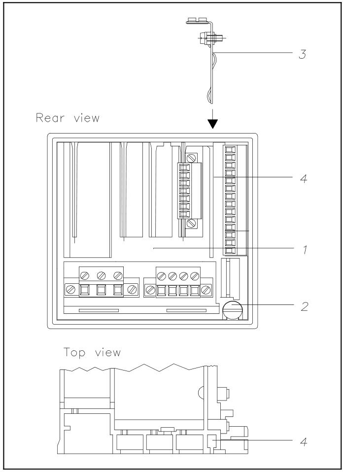
Module installation and replacement: Before installation, all hazardous voltages need to be disconnected. Remove the sub component by rotating the twisting screw of the sub component, insert the module into the guide slot from above and install it on the bus PCB, then push back the sub component and lock it; The installation and disassembly of the bus PCB require the use of a screwdriver to operate the snap fastener.
Power supply and grounding
Power connection: Supports 115/230V AC (90-260V, 47-63Hz) or 24V UC. Please follow the relevant power installation specifications and connect the protective grounding conductor before connection. The 24V power supply also needs to be connected to the grounding conductor.
Shielding treatment: A shielding terminal board needs to be installed to fix the shielding layer of the data cable on the contact surface. If there are auxiliary wires in the shielding layer, they can be connected to the terminal.
Technical Parameter
Input: Universal input resolution of 12 bits, measurement tolerance ≤ 0.2% (relative to nominal range), temperature impact ≤ 0.2%/10 ℃; Binary input/output is configurable, with a nominal input level of 24V DC and a maximum output of 100mA.
Output: Analog output 0/4... 20mA (maximum 750 Ω, short circuit and open circuit protection), resolution of 12 bits; The maximum output of the relay is 250V AC, 1A.
Environmental conditions: working temperature 0... 50 ℃, storage temperature -20... 70 ℃, relative humidity ≤ 75% (annual average), short-term up to 95% (slight condensation allowed); Meets EMC related standards and has strong anti-interference ability.
Mechanical parameters: front panel protection level IP65, shell IP30, terminal IP20; The panel size is 96mm × 96mm, the installation depth is 200mm, the weight is 1kg (without modules), each module weighs about 40g, and the relay module weighs about 80g.
Other information
Firmware upgrade and configuration: The firmware can be updated by replacing the IC. To enable free configuration, a specific IC is required. If the password is lost, it can be reset by adjusting the jumper.
Packaging and Accessories: Insulation and buffering should be done for transportation or return packaging. Accessories include various modules, bus PCBs, PC cables, adapters, etc. Please refer to the catalog number when ordering.
- OMRON
- ABB
- General Electric
- EMERSON
- Honeywell
- HIMA
- ALSTOM
- Rolls-Royce
- MOTOROLA
- Rockwell
- Siemens
- Woodward
- YOKOGAWA
- FOXBORO
- KOLLMORGEN
- MOOG
- KB
- YAMAHA
- BENDER
- TEKTRONIX
- Westinghouse
- AMAT
- AB
- XYCOM
- Yaskawa
- B&R
- Schneider
- KONGSBERG
- NI
- WATLOW
- ProSoft
- SEW
- ADVANCED
- Reliance
- TRICONEX
- METSO
- MAN
- Advantest
- STUDER
- DANAHER MOTION
- Bently
- Galil
- EATON
- MOLEX
- DEIF
- B&W
- ZYGO
- Aerotech
- DANFOSS
- Beijer
- Moxa
- Rexroth
- Johnson
- WAGO
- TOSHIBA
- BMCM
- SMC
- HITACHI
- HIRSCHMANN
- Application field
- XP POWER
- CTI
- TRICON
- STOBER
- Thinklogical
- Horner Automation
- Meggitt
- Fanuc
- Baldor
- SHINKAWA
- Other Brands
- UniOP
- KUKA
- Iba
- Beckhoff
- ADLINK
-
 SIGMATEK SDD310-2 Servo Drive
 -
 SIGMATEK AI084 Analog Input Module
 -
 SIGMATEK CRCH081 12-752-081 Temperature Module
 -
 Sigma-Tek 5000L-4 Attitude Gyro 1U284-001-3
 -
 SIGMATEK CM5V020 12-250-023-K Wiring Module
 -
Sigma-Tek 4000H-6 Directional Gyro IU262-035-7
-
 SIGMATEK Dias DCP160 05-004-160 Processor Module
 -
 SIGMATEK 0147.395.02 Control Module
 -
 SIGMATEK A1084 Control Module
 -
SIGMATEK DI200 20-006-2000 Digital Input Module
-
 Sigmatek DNC115 Encoder Module
 -
 Sigmatek DAM122 05-017-122 Analog Module
 -
 Sigmatek 9802.289.01 Control Board TA71 Display
 -
Sigmatek TO127 20-007-127 Digital Output Module
-
Sigmatek DNC031 05-011-031 Digital Module
-
 Sigmatek VI022 20-003-022 Interface Module
 -
 Sigmatek CAI085 Analog Input Module
 -
 Sigmatek CP111 S-DIAS CPU Module
 -
 Sigmatek CTMS030 Krauss Maffei Module
 -
 Sigmatek CAM123 Control Module
 -
 Sigmatek TAE732-P 01-240-732-P Touch Display Unit
 -
 Sigmatek MDM021 Digital Mixed Module
 -
Sigmatek DCP642 DIAS Central Unit
-
 Sigmatek CST022 12-014-022 C-DIAS Module
 -
 Sigmatek SRO021 20-893-021 Safety Relay Output
 -
 Krauss Maffei MC5 Control System Sigmatek
 -
 Sigmatek DC061 Module 18-24VDC 300mA
 -
 Herrmann EVT0855 Ultrasonic Welder Touch Panel
 -
 Sigmatek CIV521 Control Module 1.4A 2W
 -
 Sigmatek DDI61 05-006-161 Digital Input Module
 -
SIGMATEK ETT312-E Touch Terminal 01-230-312
-
Cessna S3326-1 Sigma Tek 5000B-67 Gyro 1U149-015-9
-
 SIGMATEK PS101 Power Supply Module
 -
 SIGMATEK 0332.554.03 Control Module 371071000154
 -
 SIGMATEK ETT312-E Touch Terminal 01-230-312
 -
SIGMATEK CDM163 Control Module
-
 SIGMATEK VSV046 16-023-046 Module
 -
SIGMATEK AM221 20-017-221 Analog Module
-
SIGMATEK CTS051 12-053-051 Control Module
-
SIGMATEK AM221 20-017-221 Analog Module
-
Sigmatek CSDI161 12-891-161 Safety Input Module
-
Sigma Tek 4000C-1 Directional Gyro Indicator
-
 Sigmatek ETV0501 12-230-0501 VARAN Terminal
 -
Sigmatek DDM165 SLIDES Module
-
 Sigmatek N100 20-011-100 Control Module
 -
Sigmatek AKM54K-ANC2R-B0 PM Servo Motor
-
Sigmatek CTO166 Digital Output Module
-
 Sigmatek CP212-K 20-004-212-K CPU Module
 -
Sigmatek CDI161 Digital Input Module
-
Sigmatek DCC080 05-700-080-2 Control Module
-
 SIGMATEK SCP011 S-DIAS Safety CPU
 -
SIGMATEK SCP011 S-DIAS Safety CPU
-
 SIGMATEK SRO022 Relay Output Module
 -
SIGMATEK MDD 121 Drive Axis Module
-
SIGMATEK DSI021 SLIDES Siemens Interface
-
SIGMATEK DIAS DCP161 Module 05-004-161
-
 Sigmatek ETT312 Built-in Touch Terminal
 -
 SIGMATEK DCP 643 DIAS Controller System
 -
SIGMATEK CIO021 Multi I/O Module
-
 SIGMATEK CTMS020 Control Module
 -
 Sigmatek CME 221 Memory Module
 -
Sigmatek 0420.615.01 Control Board
-
 Sigmatek CP111 20-004-111 CPU Module
 -
Sigmatek 9405.065.03 Control Board
-
 Sigmatek ETEK 01-450-032-K C-IPC 256MB Industrial PC
 -
 Sigmatek CTO163 12-007-163 Safety Output Module
 -
Sigmatek TO081 20-007-081 Digital Output Module
-
 Sigmatek SI021 20-022-021 Safety Input Module
 -
 Sigmatek 05-052-014 Control Module HW 1.0
 -
Sigmatek TO127 20-007-127 Digital Output Module
-
Sigmatek SV141 20-023-141 VARAN Splitter
-
 SIGMATEK CIV513 C-DIAS VARAN Control Module
 -
Sigmatek DCP 642 SLIDES Control Module with DKL002
-
 Sigma-Tek 5000B-36 Attitude Gyro
 -
SIGMATEK 01-450-024 C-IPC Industrial Computer
-
 SIGMATEK CP102 S-DIAS Processor Module
 -
Sigmatek CRCH081 12-752-081 PLC Module
-
SIGMATEK SDD340-46 Series Drive
-
SIGMATEK TAE731 Touch Display Unit
-
 SIGMATEK CDM167 Module 12-008-167-O
 -
SIGMATEK TO161 Digital Output Module
-
 Sigmatek NC4 45291000003 Control Board
 -
 Sigmatek HGW1033-3 Handheld Wireless Unit
 -
Sigmatek CAI0811 Analog Input Module
-
 Sigmatek STO081 S-DIAS Safety Output Module
 -
 Sigmatek C-IPC 01-450-171-V Industrial PC
 -
 Sigmatek S1 032-8AF61-R4 EZ Servo Motor
 -
Sigmatek CM5V020 Baseplate 12-250-021-K
-
 Sigmatek HGT833-W Panel
 -
 Sigmatek NC4 45291000003 Control Module
 -
 SIGMATEK 12-780-012 R8-IPC Geode LX800
 -
SIGMATEK CCP081 Processor Module
-
SIGMATEK SCP011 S-DIAS Safety CPU
-
 SIGMATEK ETT1533 Touchscreen 01-230-1533
 -
SIGMATEK AI043 Analog Input Module
-
SIGMATEK CTMS020 Control Module
-
 SIGMATEK SLIDES VARAN Interface VAC 012
 -
 SIGMATEK Compact Control Unit 06038666
 -
 SIGMATEK CP112 Control Module
 -
SIGMATEK MDP 101-1 Power Supply Module
-
 Sigmatek CCP621 C-SLIDES Processor Module
 -
Sigmatek MDD111 Axle Module
-
Sigmatek CCL912 C-SLIDES CPU PSU Module
-
Demag NC4 0332.554.03 Sigmatek Control Board
-
Sigmatek Krauss Maffei PC321-K Control Cabinet PC
-
 Sigmatek CNC W150 Circuit Board Wittmann Robot
 -
Sigmatek AKM44G-ANCNGBB0 Servo Motor
-
 Sigmatek CSCP011 Safety Module 12-890-011
 -
Mannesmann Demag Sigmatek CP126 Central Unit
-
 Sigmatek ISE021 Interface Module 20-101-021
 -
Sigmatek CCP251 C-DIAS Processor Module
-
 SIGMATEK ET 352 Terminal
 -
SIGMATEK SV141 Module 20-023-141
-
 SIGMATEK NC-337 3 Axis Module
 -
 Sigmatek MDP 101 Power Module
 -
SIGMATEK HGT834-W Teach Pendant
-
Sigmatek C-DIAS Processor Module CCL912
-
SIGMATEK CP627 Module
-
 SIGMATEK PC 323-K Controller
 -
SIGMATEK MDD121 Controller Module
-
 SIGMATEK ICA111 Module
 -
SIGMATEK MDD 121-1 Drive Axis Module
-
SIGMATEK M5V121 12-300-121 Krauss Maffei M5 Display Unit
-
SIGMATEK CTMS 020 CD Technology Module 12-250-011
-
SIGMATEK PCT122 Touch Panel
-
Stöger MCS4100 SIGMATEK Control Module
-
SIGMATEK Krauss Maffei M5 Keyboard Unit M5K902 12-310-902
-
 SIGMATEK SD310-2 Servo Drive Module


