
Beijer Mitsubishi Electric E1000 Series Operation Panel
The maximum ambient temperature for horizontal installation is 40 ° C, and for vertical installation it is 50 ° C.
There is an explosion risk warning, such as not disconnecting the equipment before power outage, component replacement may affect applicability, only UL and cUL certified expansion units are allowed to be connected (currently there are no relevant evaluated units), batteries need to be replaced in non hazardous areas, and AWG 28-12 cables need to be used to connect the power supply, with a minimum tightening torque of 0.5 Nm, and can only be used in 4X shell flat rooms.
Beijer Mitsubishi Electric E1000 Series Operation Panel
Safety precautions
UL and cUL installation requirements
The equipment is only suitable for Class I Zone 2 (Groups A, B, C, D) or non hazardous locations. The combination of equipment in the system must be inspected by the local competent department.
The maximum ambient temperature for horizontal installation is 40 ° C, and for vertical installation it is 50 ° C.
There is an explosion risk warning, such as not disconnecting the equipment before power outage, component replacement may affect applicability, only UL and cUL certified expansion units are allowed to be connected (currently there are no relevant evaluated units), batteries need to be replaced in non hazardous areas, and AWG 28-12 cables need to be used to connect the power supply, with a minimum tightening torque of 0.5 Nm, and can only be used in 4X shell flat rooms.

General Safety Rules
It is necessary to carefully read the safety precautions, inspect for transportation damage, and promptly notify the supplier. The use of equipment in high explosive risk environments is prohibited.
Suppliers are not responsible for modifying, altering, or reassembling equipment and may only use components and accessories that meet the supplier's specifications.
Before installation, use, or maintenance, it is necessary to read the relevant instructions to prevent liquids, metal debris, etc. from entering the equipment and causing fires or electric shocks, and only qualified personnel are allowed to operate.
The storage temperature of the device must meet the requirements, otherwise it may cause the LCD display liquid to solidify or denature. If the display liquid comes into contact with the skin or eyes, it should be handled in a specific way.
The illustrations in the manual are for illustration purposes only, and the supplier is not responsible for the actual use based on the illustrations, nor does they guarantee that the equipment is suitable for specific applications or assume responsibility for product design, installation, or operation.
Safety during installation
The operation panel should be fixedly installed on a flat surface without high explosion risk, strong magnetic field, direct sunlight, or drastic temperature changes, and installed and grounded according to the installation instructions, and only by qualified personnel.
High voltage cables, signal lines, and power lines need to be separated, and the voltage and polarity should be confirmed to be correct before connecting the power supply. Peripheral equipment should be adapted to the application scenario and location.
Safety during use
Keep the control panel clean. Emergency stop and other safety functions cannot be controlled by the control panel. Avoid using excessive force or sharp objects when operating buttons or touch screens.
Service and Maintenance of Security
Only qualified personnel are allowed to carry out repairs, following the agreed warranty terms. Before cleaning or maintenance, the power must be disconnected, and the display panel and front cover must be cleaned with a soft cloth and mild cleaning agent. The battery must be replaced according to the supplier's recommended model to avoid accidental replacement and explosion.
Disassembly and scrapping safety
The operation panel or its components need to be recycled according to local regulations. Components such as lithium batteries, electrolytic capacitors, and displays contain substances that may harm health and the environment.
Product Introduction
Product Model Classification and Parameters
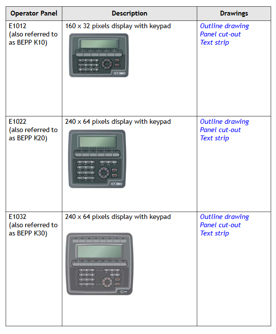
The E1000 series operation panel is divided into keyboard operation type and touch screen operation type. The specific models, descriptions, and corresponding drawings are as follows:
Type and Model Description Drawing
Keyboard operated E1012 (BEPP K10) 160 × 32 pixel display screen with keyboard outline, panel cutout, and text bar
E1022 (BEPP K20) 240 × 64 pixel display screen with keyboard outline, panel cutout, and text bar
E1032 (BEPP K30) 240 × 64 pixel display screen with keyboard outline, panel cutout, and text bar
E1060/E1062 (BEPP K60) 5.7-inch display screen with keyboard outline, panel cutout, and text bar
E1070 (BEPP 64K) 6.5-inch display screen with keyboard outline, panel cutout, and text bar
E1100 (BEPP 104K) 10.4-inch display screen with keyboard outline, panel cutout, and text bar
Touch screen operation type E1041/E1043 (BEPP T40) 3.5-inch touch screen display outline and panel cut diagram
E1061/E1063 (BEPP T60) 5.7-inch touchscreen display outline drawing and panel cutout drawing
E1071 (BEPP 64T) 6.5-inch touchscreen display outline drawing and panel cutout drawing
E1101 (BEPP 104T) 10.4-inch touchscreen display outline and panel cutout diagram
E1151 (BEPP 150T) 15 inch touchscreen display outline and panel cutout diagram

Maintenance Requirements
Before maintenance, it is necessary to carefully read the instructions. Only qualified personnel are allowed to operate. Follow the warranty and license agreement. Equipment damage caused by personnel will void the warranty.
Before cleaning or maintenance, disconnect the power supply and use a soft cloth and mild cleaning agent (such as water, isopropanol, or hexane) to clean the display panel and front cover. The battery should be replaced according to the recommended model to prevent explosion. All repaired parts are covered by a 6-month warranty.
Maintenance personnel can perform operations such as back cover replacement, battery replacement, backlight replacement, and complete front cover replacement.
Service and Maintenance Regulations
Only authorized companies are allowed to provide services and repairs. Unauthorized company operations will result in the warranty being invalidated. If training is required, please contact the supplier.
All maintenance must be carried out within the temperature range of 15-30 ° C. The warranty for equipment damage caused by personnel is invalid, and the customer contract takes precedence over the document information.
Disassembly and scrapping requirements
The operation panel or its components must be recycled according to local regulations. Lithium batteries, electrolytic capacitors, displays, and other materials that may pose a risk to health and the environment.
Hardware related content
Hardware Overview
Before the operation panel is launched, it needs to be tested by an independent organization. For example, the E1000 series needs to pass CE, UL and other standard tests. Manufacturers have quality and environmental policy requirements for suppliers and subcontractors.
Hardware Testing
Manufacturers conduct comprehensive hardware testing before obtaining approval for the control panel, with some testing performed by external testing companies such as the Swedish National Testing and Research Institute. All products must pass the testing before leaving the factory.
Hardware specifications
Keyboard operation panel
There are differences in the technical parameters of different types of keyboard operation panels, and the following are the main model parameters:
Parameter E1012 E1022 E1032 E1060 (hardware version 07900 and above) E1062 E1070 E1100
Front panel dimensions (W x H x D) 155 x 114 x 6mm 155 x 155 x 6mm 202 x 187 x 6mm 275 x 168 x 6mm -285 x 177 x 6mm 382 x 252 x 6mm
Installation depth 46.4mm (including gap 146.4mm) -57mm (including gap 157mm) -57mm (including gap 157mm) -56mm (including gap 156mm) 58mm (including gap 158mm)
Front panel protection level IP 66- IP 66 IP 66- IP 66-
Rear panel protection level IP 20- IP 20 IP 20- IP 20-
Keyboard material: Thin film switch keyboard with metal shrapnel, Autotex F207 laminated (back printed), operable up to 1 million times - Thin film switch keyboard with metal shrapnel, Autotex F157 laminated (back printed), operable up to 1 million times - Thin film switch keyboard with metal shrapnel, Autotex F157 laminated (back printed), operable up to 1 million times - Thin film switch keyboard with metal shrapnel, Autotex F157 laminated (back printed), operable up to 1 million times-
Back Material Powder Coated Aluminum Powder Coated Aluminum Powder Coated Aluminum Powder Coated Aluminum Powder Coated Aluminum-
Weight 0.45kg 0.55kg 0.95kg 1.2kg-1.4kg 2.5kg
RS232C serial port 9-pin D-sub male, with 4-40 UNC standard locking screw -9-pin D-sub male, with 4-40 UNC standard locking screw -9-pin D-sub male, with 4-40 UNC standard locking screw -9-pin D-sub male, with 4-40 UNC standard locking screw-
RS422/RS485 serial port -25 pin D-sub female head (chassis mounted) with 4-40 UNC standard locking screw, 25 pin D-sub female head (chassis mounted) with 4-40 UNC standard locking screw -25 pin D-sub female head (chassis mounted), with 4-40 UNC standard locking screw-
Ethernet is connected through the Ethernet expansion module installed on the back - shielded RJ45 shielded RJ45 shielded RJ45 shielded RJ45-
USB - A-type host (USB 1.1), maximum output current 500mA A-type host (USB 1.1), maximum output current 500mA - A-type host (USB 1.1500mA), B-type device (USB 1.1)-
Application flash 512kB -12MB (including fonts) 12MB (including fonts) -12MB (including fonts)-
Real time clock ± 20 PPM, affected by ambient temperature and power supply voltage, maximum monthly error of 1 minute at 25 ° C, temperature coefficient 0.004ppm/° C ² - same left same left - same left-
Real time clock battery MS614S (UL and cUL: SII Micro Parts LTD) - CR2450 (UL and cUL: Sanyo or Panasonic), minimum lifespan of 3 years CR2450 (UL and cUL: Sanyo or Panasonic), minimum lifespan of 3 years - CR2450 (UL and cUL: Sanyo or Panasonic), minimum lifespan of 3 years-
Normal power consumption at rated voltage: 0.1A, maximum 0.3A - normal 0.15A, maximum 0.35A - normal 0.2A, maximum 0.4A - normal 0.3A, maximum 0.5A - normal 0.4A, maximum 0.9A - normal 0.5A, maximum 1.0A
Display screen FSTN-LCD, 160 × 32 pixels, monochrome transmission negative display, LED backlight (lifespan>47000h at 25 ° C) FSTN-LCD, 240 × 64 pixels, monochrome transmission negative display, LED backlight (lifespan>47000h at 25 ° C) FSTN-LCD, 240 × 64 pixels, monochrome semi transparent and semi reflective, LED backlight (lifespan>35000h at 25 ° C) TFT-LCD, 320 × 240 pixels, 64K colors, LED backlight (lifespan>20000h at 25 ° C) TFT-LCD, 320 × 240 pixels, 16 grayscale TFT-LCD, 640 × 480 pixels, 64K colors, CCFL backlight (lifespan>50000h at 25 ° C) h) TFT-LCD, 800 × 600 pixels, 64K colors, CCFL backlight (lifespan>50000h at 25 ° C)
Effective area of display screen (W × H) 89.6 × 17.9mm 90.2 × 24.0mm 127.0 × 33.8mm 115.2 × 86.4mm -131.5 × 98.6mm 211.2 × 158.4mm
Internal DC fuse, 1.0AT, 5 × 20mm - Internal DC fuse, 2.0AT, 5 × 20mm - Internal DC fuse, 2.0AT, 5 × 20mm - Internal DC fuse, 3.15AT, 5 × 20mm-
Power supply+24V DC (20-30V DC), power connector; CE: Must comply with IEC 60950 and IEC 61558-2-4; UL and cUL: Must comply with Class II power requirements - Same Left Same Left Same Left-
Environmental temperature 0-50 ° C - vertical 0-50 ° C, horizontal 0-40 ° C - vertical 0-50 ° C, horizontal 0-40 ° C - vertical 0-50 ° C, horizontal 0-40 ° C-
Storage temperature -20-70 ° C -20-70 ° C -20-70 ° C -20-70 ° C -20-70 ° C-
Relative humidity 5-85% (no condensation) -5-85% (no condensation) -5-85% (no condensation) -5-85% (no condensation)-
- OMRON
- ABB
- General Electric
- EMERSON
- Honeywell
- HIMA
- ALSTOM
- Rolls-Royce
- MOTOROLA
- Rockwell
- Siemens
- Woodward
- YOKOGAWA
- FOXBORO
- KOLLMORGEN
- MOOG
- KB
- YAMAHA
- BENDER
- TEKTRONIX
- Westinghouse
- AMAT
- AB
- XYCOM
- Yaskawa
- B&R
- Schneider
- KONGSBERG
- NI
- WATLOW
- ProSoft
- SEW
- ADVANCED
- Reliance
- TRICONEX
- METSO
- MAN
- Advantest
- STUDER
- DANAHER MOTION
- Bently
- Galil
- EATON
- MOLEX
- DEIF
- B&W
- ZYGO
- Aerotech
- DANFOSS
- Beijer
- Moxa
- Rexroth
- Johnson
- WAGO
- TOSHIBA
- BMCM
- SMC
- HITACHI
- HIRSCHMANN
- Application field
- XP POWER
- CTI
- TRICON
- STOBER
- Thinklogical
- Horner Automation
- Meggitt
- Fanuc
- Baldor
- SHINKAWA
- Other Brands
- UniOP
- KUKA
- Iba
- Beckhoff
- ADLINK
-
 SIGMATEK 0332.554.03 Board 371071000154
 -
 SIGMATEK 12-250-021 Base Plate Back Panel CM5V020
 -
 SIGMATEK DM162 S-DIAS Digital Mix Module
 -
 DEMAG ERGOTECH 061 381 66 Sigmatek 9842.243.02 Circuit Board
 -
 SIGMATEK CP313-1 PLC Module
 -
 Sigmatek ETV0551-2 VARAN Touch Terminal
 -
 Sigmatek SDM 081 FS S-Dias Safety Module
 -
 DEMAG 05-250-023 Ergotech Motherboard with Sigmatek TMS012
 -
Sigmatek CM5V020 12-250-023-K Wiring Base
-
 Sigma Tek 5000B-37 Attitude Gyro Indicator
 -
 Sigmatek SDD120-2 DIAS Drive
 -
 Sigmatek CME221 Memory Module
 -
 Sigmatek DCP640 DIAS Central Unit
 -
 Sigmatek STO040 Safety Output Module
 -
 Sigmatek CET281 Control Panel
 -
 Sigmatek CIPC LX800 Demag NC5 CPU
 -
 Sigmatek DKL093 05-024-093 Terminal Module
 -
 Sigmatek AI088 20-009-088 Analog Input Module
 -
 Sigmatek CAI888 Analog Input Module
 -
 SIGMATEK CCA021 12-025-021 Analog Output Module
 -
SIGMATEK 1104.579.05 Control Module
-
SIGMATEK SDI100 Digital Input Module
-
 SIGMATEK C-IPC 256MB LX800 Compact Dias
 -
 SIGMATEK 9423.090.02 Control Module
 -
SIGMATEK C-IPC 256 Power Supply 148498
-
 SIGMATEK CAI025 Analog Input Module
 -
 SIGMATEK CTO166 Digital Output Module
 -
 SIGMATEK CP112 20-004-112 Processor Module
 -
SIGMATEK CAI887 12-009-887 Safety Module
-
 Sigma-Tek 4000B-31 Directional Gyro 1U262-002-42
 -
Sigmatek C-IPC 256MB LX800 IPC Controller
-
Sigmatek C-IPC 01-450-031 Industrial PC LX800
-
Sigmatek C-IPC 256 Industrial PC Controller
-
Sigmatek CCP-531 PLC Processor Module
-
Sigmatek CDI163 Digital Input Module
-
 Sigmatek ETV0501 VARAN Terminal 12-230-0501
 -
 Sigmatek CTMS020 C-DIAS Technology Module
 -
 Sigmatek CIV512 VARAN Switch Module
 -
 Sigmatek HU011 20-080-011 Interface Module
 -
 SIGMATEK SLIDES DAM 124 Module
 -
 SIGMATEK C-IPC 161 01-450-161L Industrial PC
 -
SIGMATEK C-IPC 128MB VIA 733MHz 01-450-024-K
-
 SIGMATEK 12-780-012 R8-IPC Geode LX800 Module
 -
SIGMATEK CAM124 Analog Module
-
 SIGMATEK S1 032-8AF61-R4 EZ Servo Motor
 -
 SIGMATEK CTO163 Digital Output Module
 -
 SIGMATEK CCP082 12-004-082 Processor Module
 -
 SIGMATEK CRCH081 C-DIAS Temperature Module
 -
 SIGMATEK PC322-K 01-310-322-K Industrial PC
 -
SIGMATEK SDD310-2 Servo Drive
-
 SIGMATEK AI084 Analog Input Module
 -
SIGMATEK CRCH081 12-752-081 Temperature Module
-
Sigma-Tek 5000L-4 Attitude Gyro 1U284-001-3
-
 SIGMATEK CM5V020 12-250-023-K Wiring Module
 -
Sigma-Tek 4000H-6 Directional Gyro IU262-035-7
-
 SIGMATEK Dias DCP160 05-004-160 Processor Module
 -
SIGMATEK 0147.395.02 Control Module
-
SIGMATEK A1084 Control Module
-
SIGMATEK DI200 20-006-2000 Digital Input Module
-
Sigmatek DNC115 Encoder Module
-
 Sigmatek DAM122 05-017-122 Analog Module
 -
Sigmatek 9802.289.01 Control Board TA71 Display
-
Sigmatek TO127 20-007-127 Digital Output Module
-
Sigmatek DNC031 05-011-031 Digital Module
-
Sigmatek VI022 20-003-022 Interface Module
-
Sigmatek CAI085 Analog Input Module
-
 Sigmatek CP111 S-DIAS CPU Module
 -
 Sigmatek CTMS030 Krauss Maffei Module
 -
 Sigmatek CAM123 Control Module
 -
 Sigmatek TAE732-P 01-240-732-P Touch Display Unit
 -
Sigmatek MDM021 Digital Mixed Module
-
Sigmatek DCP642 DIAS Central Unit
-
 Sigmatek CST022 12-014-022 C-DIAS Module
 -
 Sigmatek SRO021 20-893-021 Safety Relay Output
 -
 Krauss Maffei MC5 Control System Sigmatek
 -
 Sigmatek DC061 Module 18-24VDC 300mA
 -
 Herrmann EVT0855 Ultrasonic Welder Touch Panel
 -
Sigmatek CIV521 Control Module 1.4A 2W
-
 Sigmatek DDI61 05-006-161 Digital Input Module
 -
SIGMATEK ETT312-E Touch Terminal 01-230-312
-
Cessna S3326-1 Sigma Tek 5000B-67 Gyro 1U149-015-9
-
SIGMATEK PS101 Power Supply Module
-
SIGMATEK 0332.554.03 Control Module 371071000154
-
 SIGMATEK ETT312-E Touch Terminal 01-230-312
 -
SIGMATEK CDM163 Control Module
-
 SIGMATEK VSV046 16-023-046 Module
 -
SIGMATEK AM221 20-017-221 Analog Module
-
SIGMATEK CTS051 12-053-051 Control Module
-
SIGMATEK AM221 20-017-221 Analog Module
-
Sigmatek CSDI161 12-891-161 Safety Input Module
-
Sigma Tek 4000C-1 Directional Gyro Indicator
-
Sigmatek ETV0501 12-230-0501 VARAN Terminal
-
Sigmatek DDM165 SLIDES Module
-
 Sigmatek N100 20-011-100 Control Module
 -
Sigmatek AKM54K-ANC2R-B0 PM Servo Motor
-
Sigmatek CTO166 Digital Output Module
-
Sigmatek CP212-K 20-004-212-K CPU Module
-
Sigmatek CDI161 Digital Input Module
-
Sigmatek DCC080 05-700-080-2 Control Module
-
 SIGMATEK SCP011 S-DIAS Safety CPU
 -
SIGMATEK SCP011 S-DIAS Safety CPU
-
SIGMATEK SRO022 Relay Output Module
-
SIGMATEK MDD 121 Drive Axis Module
-
SIGMATEK DSI021 SLIDES Siemens Interface
-
SIGMATEK DIAS DCP161 Module 05-004-161
-
 Sigmatek ETT312 Built-in Touch Terminal
 -
SIGMATEK DCP 643 DIAS Controller System
-
SIGMATEK CIO021 Multi I/O Module
-
SIGMATEK CTMS020 Control Module
-
 Sigmatek CME 221 Memory Module
 -
Sigmatek 0420.615.01 Control Board
-
Sigmatek CP111 20-004-111 CPU Module
-
Sigmatek 9405.065.03 Control Board
-
Sigmatek ETEK 01-450-032-K C-IPC 256MB Industrial PC
-
Sigmatek CTO163 12-007-163 Safety Output Module
-
Sigmatek TO081 20-007-081 Digital Output Module
-
 Sigmatek SI021 20-022-021 Safety Input Module
 -
Sigmatek 05-052-014 Control Module HW 1.0
-
Sigmatek TO127 20-007-127 Digital Output Module
-
Sigmatek SV141 20-023-141 VARAN Splitter
-
 SIGMATEK CIV513 C-DIAS VARAN Control Module
 -
Sigmatek DCP 642 SLIDES Control Module with DKL002
-
Sigma-Tek 5000B-36 Attitude Gyro
-
SIGMATEK 01-450-024 C-IPC Industrial Computer
-
SIGMATEK CP102 S-DIAS Processor Module
-
Sigmatek CRCH081 12-752-081 PLC Module
-
SIGMATEK SDD340-46 Series Drive
-
SIGMATEK TAE731 Touch Display Unit


