Woodward EPG electric speed regulator
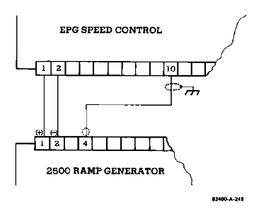
Application of using a ramp generator: slows down the speed change between idle and rated speed, without affecting steady-state speed, and controls the rate of change through acceleration and deceleration potentiometers.
Parallel generator application: Load sensors are used for synchronous or droop parallel connection. When isolating the bus, synchronous load distribution is usually selected. When parallel connected with infinite bus or incompatible electric speed controllers, droop operation is required.

Troubleshooting process
When there is a problem with the operation of the prime mover, it is necessary to first determine whether the fault is caused by the governor. The following methods can be used to troubleshoot:
Component replacement: Replace suspected faulty components with known normal ones.
System simplification: Gradually remove optional components and observe the performance changes after each removal.
Component testing: Test the output of suspected faulty components according to the manufacturer's instructions or known input and operating conditions.
When testing EPG, you can refer to the installation inspection steps in Chapter 2, where using a signal generator with isolated output for rated speed preset is the best way to test EPG speed control capability. If it involves the application of parallel generators, it is also necessary to refer to the inspection content of load sensors in the 82313 manual mentioned in Chapter 2.
Other inspection items
Unstable speed or power output
If the prime mover remains stable at certain speeds or power outputs but oscillates in other situations, it may be due to incompatibility between the linkage device and fuel control. Please refer to the "Linkage Device Compatibility" section under "Installation of actuators and linkage devices" in Chapter 2.
If there is a low-frequency oscillation of about 1Hz in the prime mover and the gain and stability adjustments in Chapter 2 are correct, it may be due to friction in the linkage device. It is necessary to disconnect the actuator from the fuel control, manually operate the fuel control linkage device, check whether it moves flexibly without friction or clearance, and lubricate or replace components if necessary.

Unstable load distribution
Verify if the current transformers (CTs) and voltage transformers (PTs) of the load sensor are wired correctly.
Check if the droop or cross current compensation settings of the voltage regulator are correct, and if there are intermittent faults or other issues with the voltage regulator.
If the problem persists, the load gain can be appropriately reduced and the load gain potentiometers of all other load sensors in the system can be set to have the same load signal at full load. In extreme cases, the load signal may need to be reduced to 3 volts. In this case, authorized dealers or Woodward can be consulted.
Fuse or circuit breaker issues
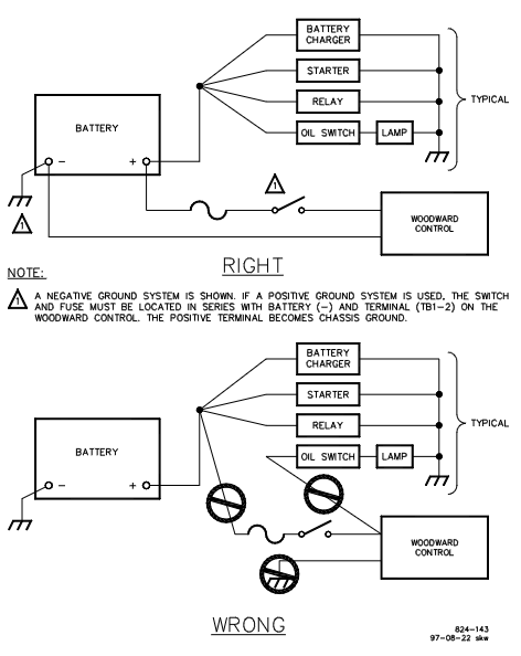
If the fuse or circuit breaker disconnects after the prime mover is running, it may be due to high voltage spikes generated by the battery or battery charger. It is necessary to separately wire from the speed controller to the battery terminal as shown at the top of Figure 2-6.
If the fuse or circuit breaker is disconnected during initial startup, it may be a battery connection error. It is necessary to verify whether the battery connection is correct, remove the wires from terminals 1 to 4, and check whether each wire is short circuited to ground.
Differences in performance between hot and cold states
If the prime mover oscillates in the cold state and stabilizes in the hot state, the gain potentiometer can be slightly rotated counterclockwise. If stability needs to be maintained, the stability potentiometer can be slightly rotated clockwise.

- ABB
- General Electric
- EMERSON
- Honeywell
- HIMA
- ALSTOM
- Rolls-Royce
- MOTOROLA
- Rockwell
- Siemens
- Woodward
- YOKOGAWA
- FOXBORO
- KOLLMORGEN
- MOOG
- KB
- YAMAHA
- BENDER
- TEKTRONIX
- Westinghouse
- AMAT
- AB
- XYCOM
- Yaskawa
- B&R
- Schneider
- Kongsberg
- NI
- WATLOW
- ProSoft
- SEW
- ADVANCED
- Reliance
- TRICONEX
- METSO
- MAN
- Advantest
- STUDER
- KONGSBERG
- DANAHER MOTION
- Bently
- Galil
- EATON
- MOLEX
- DEIF
- B&W
- ZYGO
- Aerotech
- DANFOSS
- Beijer
- Moxa
- Rexroth
- Johnson
- WAGO
- TOSHIBA
- BMCM
- SMC
- HITACHI
- HIRSCHMANN
- Application field
- XP POWER
- CTI
- TRICON
- STOBER
- Thinklogical
- Horner Automation
- Meggitt
- Fanuc
- Baldor
- SHINKAWA
- Other Brands


