
Woodward EPG electric speed regulator
Woodward EPG electric speed regulator
Overview
This manual covers models 512/524 and 1712/1724 of Woodward EPG (Electrically Powered Governor) electric governors, including synchronous models, covering installation, operation, calibration, troubleshooting, and other content. It is suitable for speed control of diesel, gas, and gasoline engines as well as gas turbines.
General information
Application scenario: Used to control the speed of diesel, gas, gasoline engines and gas turbines, suitable for prime movers of mechanical loads and generator loads. Parallel generator sets require additional equipment and Woodward generator load sensors.
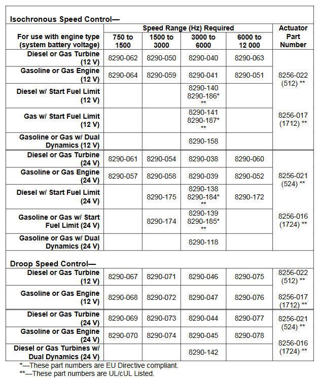
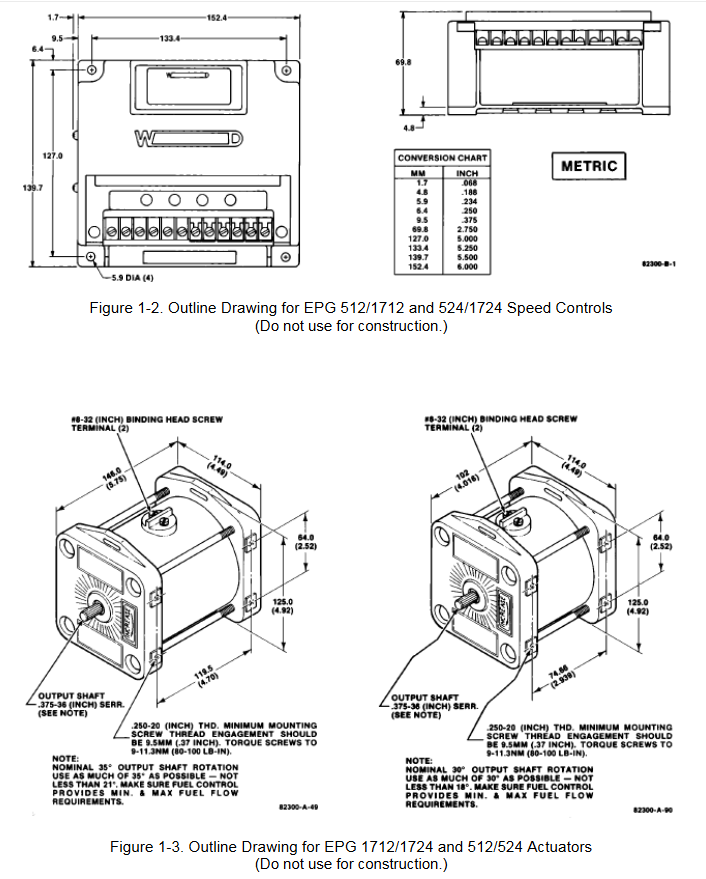
Model selection: 512/1712 models are used for 12V systems, and 524/1724 models are used for 24V systems. The speed controller has four frequency ranges for magnetic and electric sensors, suitable for different engine types. The actuator has a dual end output shaft that can rotate clockwise or counterclockwise to increase fuel consumption. You can also choose to activate functions such as fuel limit and dual dynamic characteristics, and select compatible speed controllers and actuators according to the model selection table.
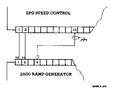
Attachment: Includes generator load sensor (for parallel generator applications), ramp generator (for slowing down acceleration and deceleration), external capacitor (providing exponential ramp), etc.
Reference materials: Relevant publications can be obtained from authorized Woodward distributors or AISF, and can also be viewed on the Woodward website.
Installation, inspection, and calibration
Installation of speed controller: The working temperature range is -40 to+75 ° C (-40 to+167 ° F), and it should be installed in a location with adjustment and wiring space, avoiding exposure to radiant heat sources, close to actuators and batteries to meet wire length requirements, and ensuring good ventilation.
Installation of actuator and linkage device: The operating temperature range of the actuator is -40 to+93 ° C (-40 to+200 ° F), avoiding exposure to excessive heat sources. Suitable linkage devices need to be selected to match the rotation direction of the actuator and fuel control, ensuring that the linkage device moves flexibly, without friction or clearance. The actuator includes a reset spring, which does not require additional addition.
Installation of magneto electric sensor: Installed through the shell or rigid bracket, ensure that the detected gear is made of magnetic material, and the gap between the sensor and the outer diameter of the gear is about 1.0 millimeter (0.04 inch) at the closest point. The gap can be set in a specific way and the anti loosening nut can be tightened.
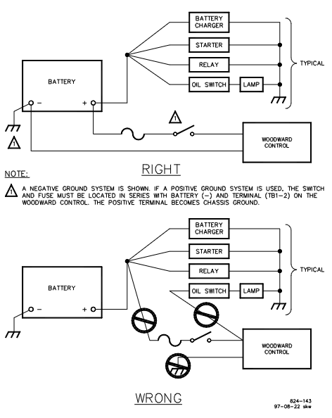
Wiring instructions: Use a specific wiring diagram for wiring, and use insulated terminals for all connections. The wiring to the actuator and battery should be as short as possible, and different models have different maximum wiring lengths. Fuses and switches or circuit breakers should be located in non grounded battery leads, and the connection between the battery and the speed controller terminal should come directly from the terminal, without passing through the distribution point. Attention should also be paid to the shielding layer connection and the installation of varistors required by EMC.
Installation inspection: including checking electrical connections, installation of magneto electric sensors, fastening of actuators and linkage devices, testing battery voltage, terminal voltage, preset rated speed and idle speed, adjusting gain and stability, setting starting fuel limits, etc. There are additional inspection steps for different application scenarios (such as applications with 2500 ramp generators and parallel generators).
Operate
The governor needs to be powered on at startup and powered off at shutdown (if the fuel control is in the minimum fuel position, power off will cause shutdown). The application of parallel generators requires synchronous and parallel operation. In droop mode, parallel operation requires adjusting the speed and fine tuning potentiometer to set the power generation. The EPG design is suitable for unmanned operation, and the idle rated switch can be controlled by multiple devices. When using the Woodward SPM synchronizer for parallel generator applications, equivalent automation operation can be achieved. The ramp generator can be used to provide adjustable speed change time between rated and idle.

Describe
Speed control application: The basic speed control components include magneto electric sensors, speed controllers, and actuators, with two control loops: speed loop and current loop. The speed loop controller compares the expected speed with the actual speed, calculates the error signal, and adjusts the gain and stability to customize the governor response; The current loop ensures the correct driving of the actuator, including relevant circuits and protection mechanisms.
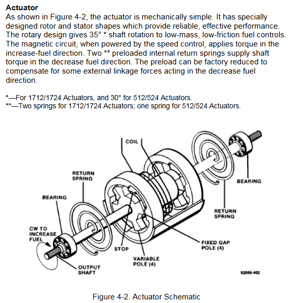
Executor: The mechanical structure is simple, with specially designed rotors and stators. The rotating design enables low-quality, low friction fuel control to achieve a certain angle of shaft rotation. When the magnetic circuit is energized, it provides torque in the direction of fuel increase, and the internal reset spring provides shaft torque in the direction of fuel decrease.
Application of using a ramp generator: slows down the speed change between idle and rated speed, without affecting steady-state speed, and controls the rate of change through acceleration and deceleration potentiometers.
Parallel generator application: Load sensors are used for synchronous or droop parallel connection. When isolating the bus, synchronous load distribution is usually selected. When parallel connected with infinite bus or incompatible electric speed controllers, droop operation is required.
Troubleshooting process
When there is a problem with the operation of the prime mover, it is necessary to first determine whether the fault is caused by the governor. The following methods can be used to troubleshoot:
Component replacement: Replace suspected faulty components with known normal ones.
System simplification: Gradually remove optional components and observe the performance changes after each removal.
Component testing: Test the output of suspected faulty components according to the manufacturer's instructions or known input and operating conditions.
When testing EPG, you can refer to the installation inspection steps in Chapter 2, where using a signal generator with isolated output for rated speed preset is the best way to test EPG speed control capability. If it involves the application of parallel generators, it is also necessary to refer to the inspection content of load sensors in the 82313 manual mentioned in Chapter 2.
Other inspection items
Unstable speed or power output
If the prime mover remains stable at certain speeds or power outputs but oscillates in other situations, it may be due to incompatibility between the linkage device and fuel control. Please refer to the "Linkage Device Compatibility" section under "Installation of actuators and linkage devices" in Chapter 2.
If there is a low-frequency oscillation of about 1Hz in the prime mover and the gain and stability adjustments in Chapter 2 are correct, it may be due to friction in the linkage device. It is necessary to disconnect the actuator from the fuel control, manually operate the fuel control linkage device, check whether it moves flexibly without friction or clearance, and lubricate or replace components if necessary.
Unstable load distribution
Verify if the current transformers (CTs) and voltage transformers (PTs) of the load sensor are wired correctly.
Check if the droop or cross current compensation settings of the voltage regulator are correct, and if there are intermittent faults or other issues with the voltage regulator.
If the problem persists, the load gain can be appropriately reduced and the load gain potentiometers of all other load sensors in the system can be set to have the same load signal at full load. In extreme cases, the load signal may need to be reduced to 3 volts. In this case, authorized dealers or Woodward can be consulted.
Fuse or circuit breaker issues
If the fuse or circuit breaker disconnects after the prime mover is running, it may be due to high voltage spikes generated by the battery or battery charger. It is necessary to separately wire from the speed controller to the battery terminal as shown at the top of Figure 2-6.
If the fuse or circuit breaker is disconnected during initial startup, it may be a battery connection error. It is necessary to verify whether the battery connection is correct, remove the wires from terminals 1 to 4, and check whether each wire is short circuited to ground.
Differences in performance between hot and cold states
If the prime mover oscillates in the cold state and stabilizes in the hot state, the gain potentiometer can be slightly rotated counterclockwise. If stability needs to be maintained, the stability potentiometer can be slightly rotated clockwise.
- OMRON
- ABB
- General Electric
- EMERSON
- Honeywell
- HIMA
- ALSTOM
- Rolls-Royce
- MOTOROLA
- Rockwell
- Siemens
- Woodward
- YOKOGAWA
- FOXBORO
- KOLLMORGEN
- MOOG
- KB
- YAMAHA
- BENDER
- TEKTRONIX
- Westinghouse
- AMAT
- AB
- XYCOM
- Yaskawa
- B&R
- Schneider
- KONGSBERG
- NI
- WATLOW
- ProSoft
- SEW
- ADVANCED
- Reliance
- TRICONEX
- METSO
- MAN
- Advantest
- STUDER
- DANAHER MOTION
- Bently
- Galil
- EATON
- MOLEX
- DEIF
- B&W
- ZYGO
- Aerotech
- DANFOSS
- Beijer
- Moxa
- Rexroth
- Johnson
- WAGO
- TOSHIBA
- BMCM
- SMC
- HITACHI
- HIRSCHMANN
- Application field
- XP POWER
- CTI
- TRICON
- STOBER
- Thinklogical
- Horner Automation
- Meggitt
- Fanuc
- Baldor
- SHINKAWA
- Other Brands
- UniOP
- KUKA
- Iba
- Beckhoff
-
 Basler Electric DECS-200-1L Digital Excitation Control System
 -
 Basler DECS125-15-B2C1 Excitation Control
 -
 Basler 9507900205 SSR Retrofit Voltage Regulator
 -
 Basler BE2000E Digital Voltage Regulator
 -
 Basler BE1-GPS Generator Protection System
 -
 Basler DECS-250-CN1CN1N Digital Excitation Control
 -
 Basler DGC-2020 Genset Controller
 -
 Basler BE1-81O UT3ED1LA7N0F Frequency Relay (Variant)
 -
 Basler BE1-81O UT3EE1YA9S0F Frequency Relay (Variant)
 -
 Basler BE1-81O Over/Under Frequency Relay
 -
 Basler DECS125-15 Digital Excitation Control
 -
 Basler Electric BE1-951 Overcurrent Protection System
 -
 Basler Electric BE1-700V Digital Protective Relay
 -
 Basler Electric APR63-5 Automatic Voltage Regulator
 -
 Basler Electric BE1-851 Overcurrent Protection System
 -
 Basler Electric DECS-250-LN1SN1N Excitation Control
 -
 Basler Electric BE1-87T Transformer Differential Relay
 -
 Basler Electric DECS-200-1L Excitation Control System
 -
 Basler Electric 9310300100 DECS-300 Excitation Control
 -
 Basler Electric SSE-N 125-4.5KW Shunt Exciter Regulator
 -
 Basler Electric DGC-2020HD-5NS1DNSBA Genset Controller
 -
Basler Electric BE1-81-O/UT3EE1JB7N1F Frequency Relay
-
 Basler Electric BE1-81T1EE1WA0N1F Frequency Relay
 -
 Basler Electric BE1-25M1EA6PN5R1F Sync-Check Relay
 -
 Basler Electric BE1-GPS Generator Protection System
 -
Basler Electric DECS-250-LN1SN1N Excitation Control Rev V
-
 Basler Electric DECS-250-CN2CN1N Excitation Control
 -
 Basler Electric BE1-50/51B-207 Overcurrent Relay
 -
Basler Electric DECS-300-C0N0 Excitation Control System
-
Basler Electric DECS-200 Digital Excitation Control System
-
Basler Electric DECS-250-LN1CN1N Excitation Unit
-
Basler Electric DECS-250 LN2SA1D Excitation Unit Specs
-
Basler Electric BE1-87T Transformer Relay Review
-
Basler Electric BE1-11 Protection System
-
Basler Electric BE1-GPS100-E4N1H1N Protection System
-
 Allen-Bradley 442G-MABH-R Safety Module
 -
 Beckhoff CX1030-0111 PLC Assembly Profile
 -
 FANUC IC693CPU364 PLC Module
 -
 Orange Denmark Type 200816 220 PLC Specs
 -
 OMRON C200H-SNT31 Sysmac PLC Module
 -
 Allen Bradley 20AB022A3AYNANC0 PowerFlex 70
 -
 OMRON C200HW-PCU01 Position Control Unit
 -
 ABB AO845A-eA Analog Output Module
 -
 OMRON CJ1M-CPU22 CPU Unit
 -
 Allen Bradley 100-E265ED11 Contactor
 -
 Honeywell 51304511-100 Interface Module
 -
 SOLEXY BXF3S0101N0018 Gateway Module
 -
 OMRON CJ2H-CPU65 CPU Unit
 -
 Automation Direct GS2-45P0 AC Drive
 -
 M68-2000 2-Axis Motion CNC Controller
 -
 OMRON CJ1M-CPU11 V3.0 PLC CPU Unit
 -
 OMRON CJ1W-NC413 4-Axis Positioning Controller
 -
 OMRON 3G2A3-PRO16 Programming Console HMI
 -
 Siemens 3VT8440-2AA04-2GA2 Molded Case Circuit Breaker
 -
 Siemens 3RT5045 Contactor Series
 -
 OMRON C200HS-CPU01-E SYSMAC PLC Controller
 -
 OMRON C500-NC103-E Positioning Control Unit
 -
 OMRON CJ1W-TC001 Temperature Control Unit
 -
 OMRON NJ301-1100 NJ-PA3001 PLC System EtherCAT
 -
 Pilz 773100 M1P Safety Relay Base Unit
 -
 Siemens SINUMERIK 840D SL NCU 720.3B with PLC 317-3 PN/DP
 -
 Siemens 6AV6618-7GD01-3AB0 HMI Panel
 -
 OMRON F150-C15E-3 Vision Mate Controller PLC Overview
 -
 Mitsubishi MELSEC A Series PLC System A63P A3ACPU A616AD A68RD3
 -
 M68-2000 2 Axis Motion Controller SCE SERVO CNC
 -
 OMRON FZ-S2M PLC Camera Vision System
 -
 VISOLUX SLVA-4K PLC Module from Elektronik GmbH
 -
 OMRON CJ1M-CPU23 V2.0 PLC CPU Unit
 -
 ABB AI86-16CHF PCB Card 5761751-9 B Specifications
 -
 Allen-Bradley 100-D140ZJ22L Contactor Overview
 -
 Merlin Gerin PB80 PLC Rack
 -
 WEIR WE203 Power Supply PLC
 -
 OMRON NX-TS3102 Temperature Input Unit
 -
 Siemens 6ES7146-6FF00-0AB0 I/O Module
 -
 Fanuc A16B-3300-0057 Circuit Board
 -
 OMRON CJ1W-IDP01 Input Module
 -
 Siemens 6FX2007-1AD13 Handheld Unit
 -
 Gems EM54 PLC Module PCB
 -
 Beckhoff CX2030-0121 Embedded PC CPU
 -
 OMRON NJ301-1100 Machine Automation Controller
 -
 Biesse Rover CNI PLC 2153 030 7146.30 Numerical Control Module
 -
 OMRON CJ1W DA08V Analog Output Module
 -
 OMRON CS1D ETN21D Ethernet Module
 -
 Allen Bradley 1768 L43 CompactLogix Controller
 -
 Schneider TWDLMDA40DTK Twido PLC Module
 -
 Mitsubishi NZ2EX2B 60AD4 Analog Input Module
 -
 OMRON NS8 TV00B V2 Touch Display Panel
 -
 Mitsubishi AY71 CMOS TTL Output Module
 -
 OMRON C500 CPU11 E Processor Module
 -
 OMRON CJ1W PTS51 Temperature Input Module
 -
 Siemens 6SL3100-1DE22-0AA1 600V DC Supply
 -
 OMRON CJ1M-CPU23 PLC CPU 9‑Pin Serial
 -
 Schlumberger IMT4N 24‑250VAC 48‑230VAC PLC Timer
 -
 OMRON CJ1M-CPU22 PLC CPU Unit V2.0
 -
 Allen‑Bradley 2711P-B7C6D2 Touch Screen PanelView
 -
 ADSP-2181KST-160 Analog Devices DSP IC Specs
 -
 Schneider LC1F400 400A Contactor Specifications
 -
 Yaskawa SGDH-10DE-OY 1kW 400V Servo Drive
 -
 Schneider TM262L10MESE8T M262 PLC 5ns Inst
 -
 Mitsubishi AA104VJ05 10.4in LCD Panel Specs
 -
 Allen Bradley 1761-L32BWA MicroLogix 1000 PLC
 -
 Siemens 6ES7431-7KF00-0AB0 Analog Input Module
 -
 Allen Bradley 1769-OB16 Output Module
 -
 Siemens 6ES7131-1BL12-0XB0 Input Module
 -
 Beckhoff EP7041-3002 EtherCAT Box Module
 -
 Siemens RK7243-2AA30-0XB0 Communication Module
 -
 Siemens 4AM5742-8DD40-0FA0 Transformer
 -
 Siemens 3TK2834-1BB40 Safety Relay
 -
 Brother BAS 311 Sewing Machine Circuit Board
 -
Yaskawa SGDH-10DE-OY Servo Driver
-
 OMRON C60H C6DR DE V1 Sysmac PLC
 -
 MITSUBISHI ELECTRIC A2ACPU21 S1 CPU Module
 -
 ABB BAILEY INNPM12 Network Process Module
 -
 HONEYWELL 620 0073C IPC PLC Module
 -
 Mitsubishi 15050 PR02B PLC Circuit Board
 -
 SIEMENS 6SY7000 0AC37 Drive Control Module
 -
 OMRON TJ2 ECT16 Traxial EtherCAT Controller
 -
 GE Fanuc IC698PSD300D Power Supply Module
 -
 Texas Instruments Series 505 16 Position Base
 -
 OMRON YASKAWA SGDH 10DE OY Servo Drive
 -
 Allen‑Bradley 440G-MT Safety Interlock Switch Specs
 -
 Rubycon PD27A 24V 8A Power Supply Module
 -
 SK-H1-GDB1-F11D PLC Gate Driver Board Kit
 -
 VIPA 441-4UA14 451-4UA14 PLC Module Rack
 -
 Mitsubishi FX5U-80MT ESS PLC Controller Specs
 -
 Mitsubishi Q64TCRTN Temperature PLC Module
 -
 GE 1C31170G Rev10 PLC Circuit Board Module
 -
 Schneider TWDLMDA40DTK PLC Controller Module


