
Thermal Solutions EVS series gas regulated boilers
Key information: Released in September 2024, replacing the old version, including bilingual warning content in English/French, to be posted and kept clear and readable. Boiler model and serial number (see rated label) must be provided during maintenance.
Thermal Solutions EVS series gas regulated boilers
Product basic information
1. Core identification and certification
Product positioning: Gas driven modular regulating boiler (GAS-FIRED MODULATION BOILER), used for hot water systems, certified by AHRI, in compliance with the National Gas Code (NFPA 54/ANSI Z223.1) in the United States, the Gas Installation Code (CAN/CSA B149) in Canada, and local regulations such as Massachusetts 248 CMR 4.00/5.00.
Key information: Released in September 2024, replacing the old version, including bilingual warning content in English/French, to be posted and kept clear and readable. Boiler model and serial number (see rated label) must be provided during maintenance.
2. Model and core parameters
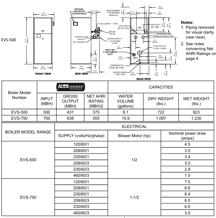
Covering 8 models (EVS-500 to EVS-3000), the core parameter differences are as follows (taking typical models as an example):
Model Input Power (MBH) Total Output (MBH) Net AHRI Rated (MBH) Water Capacity (gallon) Dry Weight (pound) Wet Weight (pound) Power Supply/Fan Power
EVS-500 500 431 375 6.1 722 823 120V/189 horsepower
EVS-1000 1000 850 739 16.4 1185 1322 120V/1.5 horsepower
EVS-2000S 2000 1732 1506 40.1 1835 2169 120V/1.5 horsepower
EVS-3000 3000 2610 2270 43.1 2193 2552 208V/2 horsepower
General restrictions: Maximum working pressure of 160 PSI, medium temperature -40~+90 ° C, ambient temperature -40~+85 ° C, condensate pH value 3-5 (requires neutralization treatment).
Installation specifications (key requirements)
1. Pre requirements
Installation qualification: It is required to be operated by a certified Plumber/Gas Fitter (mandatory in Massachusetts). Before installation, local regulations must be confirmed to ensure a safe distance from combustible materials (6 inches left/right/back, 24 inches front, 18 inches for flue connections, and 24-36 inches for maintenance spacing depending on the model).
Space and ventilation: Determine whether a "non confined space" (≥ 50 ft ³/1000 Btu/h) or a "confined space" based on the space volume and total gas input. A confined space requires two permanent ventilation openings (within 12 inches at the top and 12 inches at the bottom, with a minimum diameter of 3 inches); Sealed combustion engine models can be exempted from indoor ventilation, but the intake pipe needs to be installed according to regulations.
2. Core system installation
(1) Ventilation system
Type: Supports positive pressure ventilation (side wall/vertical, maximum equivalent length of 50 feet, non confluent) and negative pressure ventilation (traditional chimney, requiring a vertical height of 15 feet or more and double acting air pressure dampers), ventilation ducts require AL29-4C ® Wait for condensation resistant materials, tilt the horizontal section at least 1 inch every 4 feet, and keep the terminal away from doors and windows (below 4 feet/horizontal 4 feet/above 1 foot) and gas meters (4 feet).
Special requirements: Massachusetts sidewall ventilation requires the installation of carbon monoxide detectors with backup batteries (1 per floor) and 8-foot high signage ("GAS VENT DirectLY BELOW. KEEP CLEAR").
(2) Water system
Water quality requirements: hardness ≤ 8.5 grains (150 ppm), pH 8.8-9.2, requiring professional water treatment (anti oxidation, scaling), ethylene glycol usage not exceeding 50%, and rust inhibitor needs to be added; The new pipe needs to be cleaned with trisodium phosphate (TSP), and the old system needs to be equipped with a filter at the return water end.
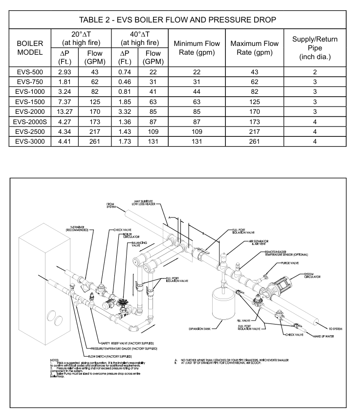
Pipeline specifications: The supply/return water diameter should be 2-4 inches (depending on the model), and the flow rate should comply with Table 2 (such as EVS-500 minimum 22 gpm, maximum 43 gpm). The return water temperature should not be lower than 130 ° F (anti condensation), and the temperature difference should not exceed 40 ° F (anti heat exchanger damage); Safety valves (not shut-off valves), exhaust devices, and expansion tanks need to be installed.
(3) Gas system
Pressure requirements: The minimum inlet pressure for natural gas is 4-9 inches of water column (depending on the model), for propane it is 8 inches of water column, and for maximum pressure it is 14 inches of water column. For overpressure, an additional pressure regulator must be installed (no multiple boilers can share one); Gas pipes need to undergo leak testing (using soapy water, no open flames), and install sediment traps and manual shut-off valves.
Pipe diameter selection: Refer to Table 4 (such as the equivalent length of 10 feet for a 1-inch SCH40 pipe with a capacity of 514 ft ³/h), and consider the equivalent length of the pipe fittings (Table 6, such as the equivalent length of 1.55-20.2 feet for a 90 ° elbow).
(4) Electrical system
Power supply: requires independent circuit and fuse switch, voltage 120/208/230/460V (depending on model), grounding in accordance with NFPA 70; Do not connect the boiler and circulating pump to the same fuse switch. Isolation relays are required for low voltage control (24V), and short circuiting of safety controls is prohibited.
Operation and debugging process
1. Check before startup
Confirm that the installation of ventilation, water, gas, and electrical systems is compliant, turn off all power sources and gas valves, empty the air in the gas pipeline (wait for 5 minutes), check for no gas leaks, and then open the gas valve.
- OMRON
- ABB
- General Electric
- EMERSON
- Honeywell
- HIMA
- ALSTOM
- Rolls-Royce
- MOTOROLA
- Rockwell
- Siemens
- Woodward
- YOKOGAWA
- FOXBORO
- KOLLMORGEN
- MOOG
- KB
- YAMAHA
- BENDER
- TEKTRONIX
- Westinghouse
- AMAT
- AB
- XYCOM
- Yaskawa
- B&R
- Schneider
- KONGSBERG
- NI
- WATLOW
- ProSoft
- SEW
- ADVANCED
- Reliance
- TRICONEX
- METSO
- MAN
- Advantest
- STUDER
- DANAHER MOTION
- Bently
- Galil
- EATON
- MOLEX
- DEIF
- B&W
- ZYGO
- Aerotech
- DANFOSS
- Beijer
- Moxa
- Rexroth
- Johnson
- WAGO
- TOSHIBA
- BMCM
- SMC
- HITACHI
- HIRSCHMANN
- Application field
- XP POWER
- CTI
- TRICON
- STOBER
- Thinklogical
- Horner Automation
- Meggitt
- Fanuc
- Baldor
- SHINKAWA
- Other Brands
- UniOP
- KUKA
- Iba
-
 LTi SO84.450 Servo Drive Controller - 450A Three-Phase BG7
 -
 LTi SO84.375 Servo Drive Controller - 375A Three-Phase BG7
 -
 LTi SO84.325 Servo Drive Controller - 325A Three-Phase BG7
 -
 LTi SO84.250 Servo Drive Controller - 250A Three-Phase BG7
 -
 LTi SO84.170 Servo Drive Controller - 170A Three-Phase BG6a
 -
 LTi SO84.143 Servo Drive Controller - 143A Three-Phase BG6a
 -
 LTi SO84.110 Servo Drive Controller - 110A Three-Phase BG6
 -
 LTi SO84.090 Servo Drive Controller - 90A Three-Phase BG6
 -
 LTi SO84.072 Servo Drive Controller - 72A Three-Phase BG5
 -
 LTi SO84.060 Servo Drive Controller - 60A Three-Phase BG5
 -
 LTi SO84.045 Servo Drive Controller - 45A Three-Phase BG5
 -
 LTi SO84.032 Servo Drive Controller - 32A Three-Phase BG4
 -
 LTi SO84.024 Servo Drive Controller - 24A Three-Phase BG4
 -
 LTi SO84.020 Servo Drive Controller - 20A Three-Phase BG3
 -
 LTi SO84.016 Servo Drive Controller - 16A Three-Phase BG3
 -
 LTi SO84.012 Servo Drive Controller - 12A Three-Phase BG2
 -
 LTi SO84.008 Servo Drive Controller - 8A Three-Phase BG2
 -
 LTi SO84.006 Servo Drive Controller - Three-Phase 230-480V 6A
 -
 LTi SO84.004 Servo Drive Controller - Three-Phase 230-480V 4A
 -
 LTi SO82.004 Servo Drive Controller - Single-Phase 230V 4A
 -
 HMS Anybus AB7646-F Gateway Manual
 -
 Schneider ATV930D75N4 Inverter Manual
 -
 Mitsubishi Q2ASHCPU-S1 System Manual
 -
 Fanuc A20B-3300-0319 Board Specification
 -
 Mitsubishi QD60P8-G Counter Module Guide
 -
 Nidec Unidrive M701 Inverter Manual
 -
 ABB AO895 Analog Output Module Guide
 -
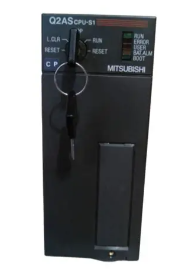 Mitsubishi Q2ASHCPU Controller System Manual
 -
 ABB Pluto S20 v2 Safety PLC Manual
 -
 Omron CJ1W-NC413 Position Module Manual
 -
 B&R X20AI4632 Analog Input Module 4 Channel
 -
 OMRON CS1G-CPU44H Ver. 4.1 CPU Unit PLC
 -
 Beckhoff EL2911-2200 TwinSAFE Logic Terminal for EtherCAT
 -
 Mitsubishi 2D-TZ368 Parallel I/O Interface Card
 -
 Mitsubishi A3ACPU PLC CPU Module for MELSEC A Series
 -
 Mitsubishi NF630-SEW 4P Adjustable Circuit Breaker 300-630A
 -
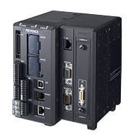 Keyence XG-8700L Multi-camera Vision System for Inspection
 -
 Beckhoff C6017-0010 Ultra Compact Industrial PC
 -
 B&R 3AT660.6 PLC Module from Automation Panel Series
 -
 GE F31X300CCHALG2 PC Board with 531X133PRUAPG1 Card
 -
 STMicroelectronics STM32L100R8T6ATR MCU Arm Cortex-M3
 -
 Omron CS1W-CLK13 Controller Link Unit
 -
 Schneider BMENOC0301 Ethernet Communication Module
 -
 HELUKABEL Braids PLC-30 40 E2UK Braided Cable Sleeve
 -
 Pe323 h0102de323a0 PLC I/O Module
 -
 Mitsubishi GT2512-STBA GT2512-STBD HMI 12.1 Inch Touch Screen
 -
 Samsung LTM213UP01 21.3 Inch LCD Monitor Panel
 -
 Allen-Bradley 440R-W23219 Guardmaster Safety Relay
 -
 Beckhoff EL2535 EtherCAT Terminal PWM Output
 -
 HELUKABEL Braids PLC-40 55 E2UK Braided Cable Sleeve
 -
 Allen Bradley 1769-OB16 16-Point Sourcing Output Module
 -
 Balluff BES 516-604-DZ-3 Delay Safety Relay for Industrial Timing
 -
 Siemens 6GK7542-1AX10-0XE0 PROFIBUS Communication Module for S7-1500
 -
 GE IC693BEM340 FIP Controller for Series 90-30 PLC
 -
 OMRON C200HG-CPU63-E Programmable Logic Controller CPU Unit
 -
 Schneider EOCR-PMZ Relay Manual
 -
 Honeywell C36TC0UA21D0 Controller Specifications
 -
 Emerson Ovation VE4001S2T2B4 Input Module
 -
 Omron CJ1M-CPU22 CPU Specifications
 -
 Grundig NEA02 AES 0 Card Specifications
 -
 Omron CJ1W-AD081-V1 Analog Input Specifications
 -
 IDEC FS1A-C21S Safety Controller Manual
 -
 IFM O3D303 Smart 3D Sensor Specifications
 -
 Siemens 6SN1123-1AB00-0BA2 Power Module Guide
 -
 B&R 4PP035.0300-01 Power Panel Manual
 -
 Siemens 6ES7 153-2BA10-0XB0 IM Module
 -
 Beckhoff EL3356-0010 Analog Input Module
 -
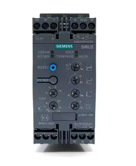 Siemens 3RW4037-1BB04 Soft Starter
 -
 Lenze EVF8216-E VFD
 -
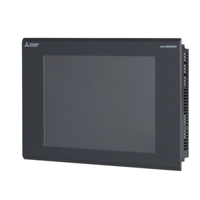 Mitsubishi GT2310-VTBA GT2310-VTBD HMI
 -
 Allen-Bradley 1764-28BXB PLC MicroLogix 1500
 -
 SP-RDM2 Relay Module Dual Reader Interface
 -
 Keyence GC-S84 Programmable Safety Controller
 -
 Mitsubishi GT2310-VTBA GT2310-VTBD HMI 10.4 Inch
 -
 Eurotherm MINI8 PLC Temperature Controller
 -
Mitsubishi GT2512-STBA GT2512-STBD HMI 12.1 Inch
-
 ABB ACS380-040S-02A6-4 VFD 0.75kW 480V
 -
 Dage PC514 ISSUE A PLC O.P.I Board
 -
 ROBICON 460T46.01 REV C Printed Circuit Board
 -
 Omron NX502-1300 Controller Unit NX5 CPU
 -
 B&R X20CM0985 PLC Module
 -
 Banner XS26-2DE 85064 Safety Controller
 -
 Siemens 3SK2122-1AA10 Safety Relay
 -
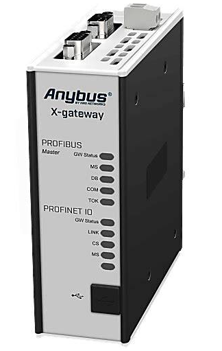 HMS Anybus AB7646-F Gateway PROFIBUS EtherNet/IP
 -
 Siemens 6SN1118-0DM11-0AA0 SIMODRIVE 611 Card
 -
 Siemens C98043-A7001-L2-4 CUD1 Control Board
 -
 Stein Sohn E 083.1 PLC Rack Module 0010026-054100A
 -
 Allen Bradley 800H-2HA7P Push Button Station
 -
 Schneider BMXNRP0200 M340 PLC Module
 -
 KEPCO BOP 200-1M Bipolar Power Supply Amplifier
 -
 Mitsubishi Q2ASHCPU PLC Module with A1SX42 A1SY42 QC24-R2 A1SD75P2-S3
 -
 Siemens Siprotec 7SJ61 Overcurrent Protection
 -
 Keyence LJ-V7000 Controller Laser Profiler
 -
 Siemens 6EP3437-8SB00-0AY0 Power Supply 20A
 -
 Pasaban MC-2006 03 CAN Bus PLC Card
 -
 ETAS ES600.2 PLC Module Prototyping
 -
 ABB ACS800-01-0005-3+P901 Frequency Converter
 -
 Omron NX102-1100 PLC Module Machine Automation
 -
 Square D BMXCPS3500 PLC Power Supply Module
 -
 Allen-Bradley 96657704 Fiber Optic Converter 1771-AF
 -
 Corcom 20VK1 Power Line Filter
 -
 Novellus 2805-11407 PLC Rack Assembly
 -
 Sick RLY3-EMSS100 Safety Relay Module
 -
 Microchip PIC12F508-I/P Microcontroller
 -
 Fanuc A02B-0098-B511 Motherboard
 -
 Merlin Gerin PB80 PLC Rack Module
 -
 ABB Pluto S20 V2 CFS Safety PLC
 -
 Honeywell TK-PRR021 Redundancy Module
 -
 B&R 7XX419L.50-1 Bus Controller
 -
 Mitsubishi NV400-SW 3P 300A Breaker
 -
 B&R X20AT2222 Temperature Module
 -
 Corcom 20VK1 EMI RFI Filter
 -
 Novellus 2805-11407 PLC Rack Assy
 -
 Mitsubishi FXAOM01BD Analog Output Module 4CH
 -
 NORIS A1-91 PCB Rack Module A1-91-4 A1-91-5 A1-91-6 A1-91-7 A1-91-8
 -
 Omron ZFV-SC50 Smart Camera Vision Sensor
 -
 Schneider Electric EOCR-PMZ Motor Protection Relay
 -
 B&R X20 SO 6300 PLC Module Safety Output
 -
 Mitsubishi A2ACPU21-S1 CPU Module MELSEC
 -
 Siemens 6ES7405-0KA02-0AA0 PS405 10A Power Supply
 -
 Samsung PVU-2424 Power Supply Unit DC24V 24W
 -
 ATTO controlSYS ATT0-CPU44 PLC with Display
 -
 Lenze EPZ-10203 CANPT010W3E Absolute Encoder
 -
 GE IS215WEMAH1A+IS210BPPBH2CAA Mark VIe Embedded Processor and Backplane Power Distribution Board
 -
 GE IS215AEPAH1CH+IS210BPPBH2CAA Mark VIe Application Processor and Backplane Power Distribution Board
 -
 GE IS215WECAH1B+IS210BPPBH2CAA Mark VIe Control Platform
 -
 GE PCM Regulator for EX2100e Power Conversion Module 151X1235DB15SA1
 -
 Lenze ECSEA048C4B servo drive


