
Watlow F4T Controller Installation and Failure
Environmental requirements for working temperature: -18~50 ℃ (-0~122 ° F); Storage temperature: -40~85 ℃; Humidity 0~90% RH without condensation
High voltage power supply specifications (F4TXX [1-4]): 85~264Vac 50/60Hz; Low voltage type (F4TXX [5-8]): 20.4~30.8Vac/dc
Power consumption 23W (maximum), 54VA
certification standard UL 61010(File E185611)、CSA 22.2#14(File 158031)、FM Class 3545、CE(EN 61326)、RoHS 2
Watlow F4T Controller Installation and Failure
Product Overview and Basic Information
1. Core parameters and authentication
Protection level: IP65 for front panel, IP10 for empty slot cover
Environmental requirements for working temperature: -18~50 ℃ (-0~122 ° F); Storage temperature: -40~85 ℃; Humidity 0~90% RH without condensation
High voltage power supply specifications (F4TXX [1-4]): 85~264Vac 50/60Hz; Low voltage type (F4TXX [5-8]): 20.4~30.8Vac/dc
Power consumption 23W (maximum), 54VA
certification standard UL 61010(File E185611)、CSA 22.2#14(File 158031)、FM Class 3545、CE(EN 61326)、RoHS 2
2. User interface and operation
Display screen: 4.3-inch TFT PCAP color touch screen, supporting 4 physical buttons (home, menu, return, help)
Core Display: Loop Name, Control Mode (Auto/Manual), Process Value (PV), Set Point (SP), Output Power (PWR)
Menu functions: configuration files (40, 50 steps per file), data logs, system settings (network/security)
Installation and wiring specifications
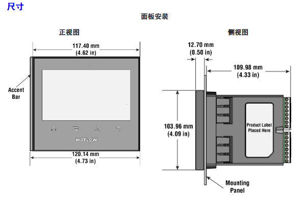
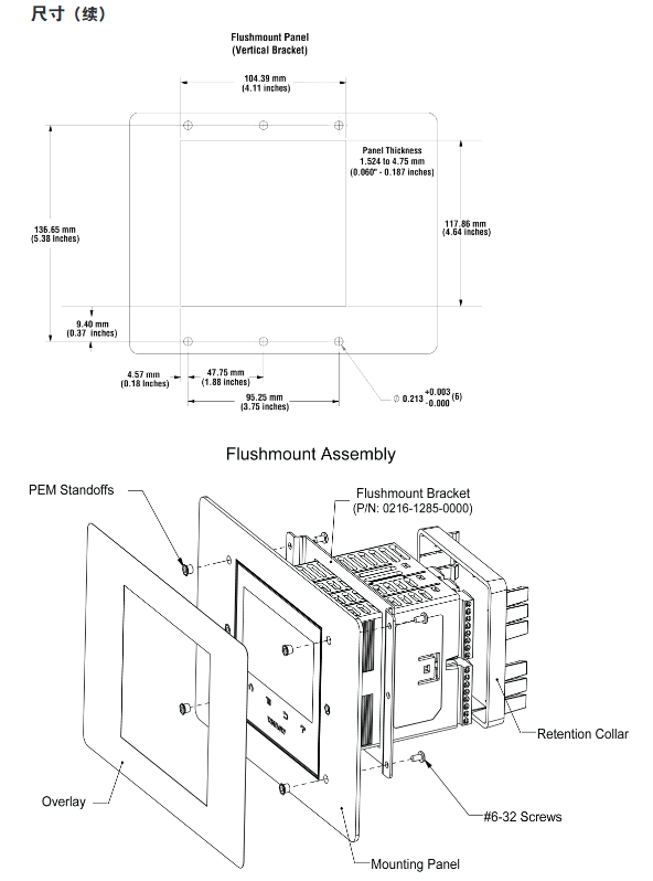
1. Installation method and size
Key requirements for installation type
Panel installation hole size: 117.40mm (width) × 120.14mm (height); The fixing ring should be tightly attached to the panel to ensure an IP65 seal
Embedded installation requires PEM nut posts (such as S0-632-6 Z1 galvanized steel); The bracket is fixed with 6 # 6-32 screws, and the front panel needs to be covered
Install through the wall with a hole of 178 × 122mm; install the heat sink vertically, leaving a ventilation space of ≥ 102mm above and below
2. Terminal wiring requirements
Input terminal:
Wire diameter: 0.0507~3.30mm ² (30~12 AWG), double wire termination ≤ 1.31mm ² (16 AWG)
Torque: 0.57Nm (5.0 lb in), wire stripping length 5.5mm
Wire/load/ground terminal:
Wire diameter: 2.5~25mm ² (14~3 AWG)
Torque: 2.7Nm (24 lb in), wire stripping length 11mm; re tighten after 48 hours, every 3-6 months
Power wiring: Terminals 98 (+) and 99 (-) should follow NEC or local electrical regulations to avoid parallel wiring with power lines
3. Installation of Elastic Module (FM)
Slot dependency rules:
The communication module (FMCA series) can only be installed in slot 6;
The high-density dual SSR module (FMHA-KAAA) requires 2 adjacent slots and cannot be placed in slots 3/6;
The module needs to be inserted with the component side facing right, and the key design prevents reverse installation.
Module identification: Confirm the part number through the black label in the lower right corner of the connector (e.g. FMMA-UKAA-AAA is 1 universal input+1 SSR output).
Input/output wiring and module specifications
1. Input wiring (some key types)
Input type wiring requires accuracy and range
Connect the negative electrode (red wire) of the thermocouple to the S terminal; The compensating wire should be made of the same alloy as the thermocouple; Input impedance>20M Ω J-type: ± 1.75 ℃ (0~750 ℃); K-type: ± 2.45 ℃ (-200~1250 ℃)
RTD (Platinum) 2-wire/3-wire, 3-wire self compensating ≤ 10 Ω lead resistance; S1 (white line) connected to R1 100 Ω (0 ℃): ± 2.00 ℃ (-200~800 ℃); 1000Ω(0℃):±2.00℃(-200~800℃)
Digital input voltage input: ≤ 36V (3mA), ≥ 3V (0.25mA) activated; Dry contact: ≤ 100 Ω activated, ≥ 500 Ω inactive update rate 10Hz; maximum short-circuit current 13mA
Current transformer input 0~50mAac; Requires Watlow 16-0246 module; The load line needs to pass through the CT in the same direction with a response time of ≤ 1 second; Accuracy ± 1mA
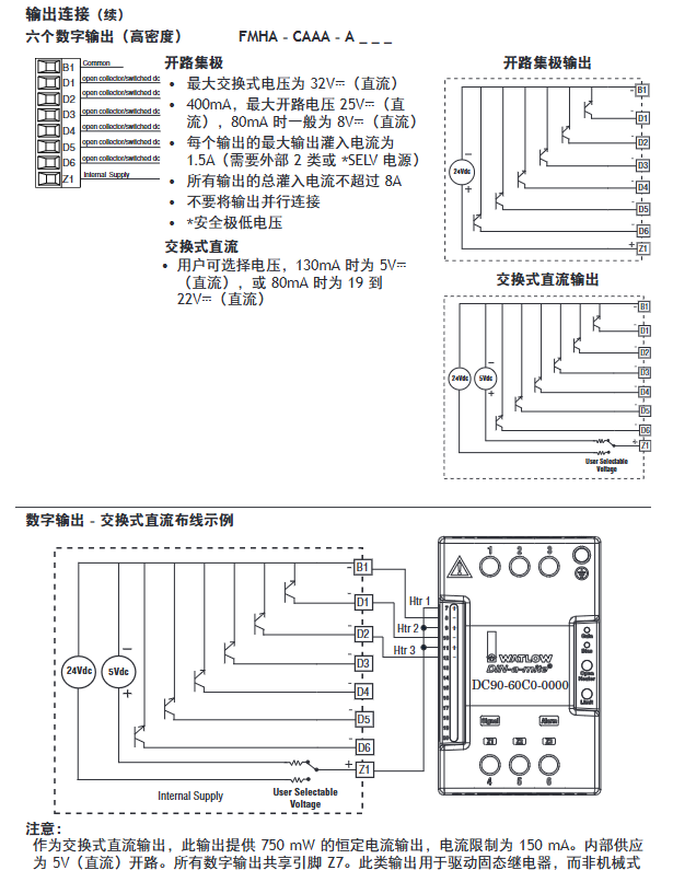
2. Output wiring (some key types)
Output type wiring requirements specification parameters
Mechanical relay 240Vac/30VDC, 5A resistance load; Minimum 20mA load at 24V; When connecting Quencac (0804-0147-0000) 120/240Vac across coils, a guiding power of 125VA is required; Rated load 100000 cycles
Solid state relay (SSR) 24~264Vac, 0.5A at 149 ° F (65 ℃), 1A at 50 ° F (10 ℃); only AC load optically isolated; The maximum off state leakage current is 105 μ A; 20VA guidance power at 120/240Vac
Switching DC 22~32VDC open circuit voltage; 2 output combination current ≤ 40mA; when driving external SSR, connect to DC+/DC - short circuit limit<50mA; DIN-A-MITE compatible
Universal process output 0~10Vdc (minimum load of 1k Ω) or 0~20mA (maximum load of 800 Ω); Voltage/current output accuracy of ± 15mV (voltage)/± 30 μ A (current) cannot be used simultaneously; Temperature stability 100ppm/℃
Calibration and PC connection
1. Calibration operation
Calibration prerequisite: Accurate signal source is required (such as thermocouple 0.000~50.00mV, RTD 50.0~350.0 Ω). It is recommended to first verify whether the error exceeds the specifications (such as thermocouple ± 1.75 ℃).
Operation method:
Composer software: Connect device → Device menu → Calibration → Select module/input → Enter 2 limit values as prompted;
Front panel: Menu → Service → Calibration → Select module/input → Perform on-site calibration.
Notes:
The calibration values will be reset to factory settings and cleared;
3-wire RTD calibration requires cross connection of R, T, and S inputs;
The security settings are divided into "full access/read only/no access", and without access permission, the calibration screen cannot be accessed.
2. PC connection and Composer software
Ethernet settings:
Default parameters: IP 192.168.0.222, subnet 255.255.255.0, gateway 0.0.0.0;
DHCP connection: F4T is connected to the switch, and the DHCP server automatically assigns an IP address;
Fixed IP connection: PC is directly connected to F4T, and the first three segments of PC IP are consistent with F4T (such as 192.168.0. XXX).
Composer software:
Function: Configure elastic module (check if slot module matches), customize function block (alarm/timer/mathematical operation);
Troubleshooting and Maintenance
1. Common faults and solutions (partial)
Possible causes and solutions for the fault phenomenon
Alarm cannot be cleared/reset. 1. Alarm latch activation; 2. Alarm source setting error 1. Reset when the process is within range; 2. Select the correct input instance
No serial communication 1. Address/baud rate mismatch; 2. EIA-485 wiring error 1. Unified device protocol parameters; 2. T+/R+connected to B, T -/R - connected to A
Temperature runaway (overshoot/undershoot): 1. Thermoelectric dipole polarity reversal; 2. Heater short circuit: 1. Connect the red wire to the S terminal; 2. Replace the heater/repair the wiring
No display 1. Power off; 2. The fuse is open circuit; 3. Voltage error: 1. Check the circuit breaker/interlock; 2. Replace the fuse; 3. Confirm 24/240Vac
The process cannot reach the set point 1. The controller is not tuned; 2. Set the control mode to "off". 1. Perform automatic tuning; 2. Set as "PID" or "on-off"
2. Battery replacement
Battery specifications: Model BR2032 (Watlow part number 0830-0858-0000), nominal voltage 3V, lifespan of 10 years at 77 ° F (25 ℃), and replacement time of 7.5 years in harsh environments.
Replacement steps:
Turn off all power sources of F4T;
Use a small screwdriver to push out the battery holder from the side hole and remove the old battery (note the polarity clearly);
Insert the positive pole of the new battery to the left and reset the battery holder;
It is recommended to recycle used batteries and not dispose of them casually.
Model ordering rules (example: F4T11A1A1AA)
Example of optional values for field meanings
The first and second product series F4=T series controller
3rd basic type T=touch screen
4th application type 1=Standard, X=Custom
The 5th future option A=none, J=data record
6th power supply and connector 1=100~240Vac right angle connector (with identification)
The 7th and 8th bits of the configuration file and function block AA=no configuration file+basic function block
Customization options for positions 9-15 (connector/firmware/document) 1A=including DVD document+gray personalized border
Key issues
Question 1: What are the types of elastic modules (FM) for F4T controllers? What are the different types of core functions and slot installation rules?
Answer:
Types and core functions of elastic modules:
Hybrid I/O module (FMMA series): includes 1 universal input (supporting thermocouple/RTD/0~10V/0~20mA)+1 output (such as SSR, mechanical relay, switched DC), used for conventional temperature acquisition and load control, such as FMMA-UKAA-AAA (1 universal input+1 SSR output);
Restriction module (FMLA series): used for safety interlock control, including 1 input (universal/thermistor)+1-2 outputs (such as C-shaped relay, supporting normally closed interlock), such as FMLA-LCJ-AAA (restriction control with universal input+switched DC output);
High density I/O module (FMHA series): integrates multiple inputs/outputs, such as FMHA-RAAA-AAA (4 universal inputs), FMHA-JAAA-AAA (4 mechanical relay outputs), suitable for multi-channel acquisition and control scenarios;
Communication module (FMCA series): Only supports Modbus RTU protocol (EIA-232/485), used for serial communication between the controller and PLC/PC, such as FMCA-2AA-AAA.
Slot installation rules:
Exclusive slot: The communication module (FMCA series) can only be installed in slot 6 and cannot be recognized in other slots;
Multi slot requirement: Some high-density modules (such as dual SSR output FMHA-KAAA) require 2 adjacent slots and cannot be placed in slot 3 (single slot design);
Keying error prevention: The module has a keying structure and cannot be inserted upside down. The component side should face right (when viewed from the back of the controller);
Label requirement: After installation, slot number labels should be affixed to the module and junction box to avoid controller failure caused by inserting the wrong slot during replacement.
Question 2: How to correctly wire the thermocouple input of F4T controller? What steps should be followed when calibrating thermocouple inputs?
Answer:
Requirements for correct wiring of thermocouples:
Polarity differentiation: The negative lead of a thermocouple is usually red and must be connected to the S terminal (signal negative) of the module, while the positive lead is connected to the R terminal (signal positive). Reversing the connections can result in incorrect temperature readings;
Compensation wire: It is necessary to use a compensation wire made of the same alloy as the thermocouple (such as K-type compensation wire for K-type) to reduce the influence of ambient temperature on readings;
Insulation requirements: The input impedance of the thermocouple should be greater than 20M Ω, and the maximum source resistance should be 2k Ω. When wiring, it is necessary to avoid parallel wiring with the power line to prevent electromagnetic interference;
Open circuit detection: The module has a built-in 3 μ A open circuit sensor for detection. If the wiring is open, it will trigger an "incorrect input" alarm.
Thermocouple input calibration steps (using Composer software as an example):
Preparation equipment: high-precision millivolt signal source (if able to output 0.000~50.000mV), copper wire (to minimize wiring error), voltage/ohmmeter (to verify the accuracy of the signal source);
Software connection: Start Composer → Connect F4T (enter IP 192.168.0.222) → Enter "Device menu → Calibration";
Select channel: Select the module where the thermocouple is located and the input channel (such as input 1 of slot 1) in the "pluggable module";
Enter calibration value:
Input the lower limit signal (such as 0.000mV, corresponding to 0 ℃) to the module, enter the actual signal value in the software, and click "Calibrate Lower Limit";
Input the upper limit signal (such as 50.000mV, corresponding to approximately 1200 ℃, depending on the thermocouple type), input the actual value, and click "Calibrate Upper Limit";
Verification and saving: After calibration, input the intermediate value (such as 25.000mV) to the module, confirm that the displayed value and actual value error are ≤ specifications (such as J-type ± 1.75 ℃), and save the calibration data;
Attention: If the factory settings are restored after calibration, the calibration values will be cleared; The calibration of a 3-wire RTD requires crossing the R, T, and S terminals, and the lead resistance should be ≤ 10 Ω.
Question 3: What are the possible reasons for the F4T controller experiencing a "temperature runaway (continuous increase after process value overshoot)" fault? What are the corresponding troubleshooting and resolution steps?
Answer:
Possible reasons:
Output function setting error (such as heating output set to cooling);
Reverse wiring of thermocouple/RTD (e.g. thermocouple red wire connected to positive electrode, RTD S1 not connected to R1);
Controller output wiring error (such as SSR output L1/L2 reversed);
Heater or wiring short circuit (causing continuous power supply to the load);
Power controller connection defects (such as DIN-A-MITE and F4T signal interruption, unable to turn off the load);
The control algorithm is set to "on-off" and the hysteresis is too large (causing the heating to not stop in time).
Troubleshooting and resolution steps:
Check the output function settings:
Front panel: Menu → Settings → Output → Select the corresponding output channel, confirm that the "Function Type" is "Heating" (not "Cooling");
If there is an error, modify it to the correct type and restart the controller to take effect;
Verify sensor wiring:
Thermocouple: Disconnect the wiring, confirm that the red wire (negative electrode) is connected to the S terminal, the positive electrode is connected to the R terminal, and if the wiring is reversed, reconnect it;
RTD: 3 wire type needs to confirm S1 (white wire) connected to R1, T1 connected to S2, lead resistance ≤ 10 Ω (measured with an ohmmeter);
Check the output wiring and load:
After the power is cut off, use a multimeter to check the on/off switch of the heater wiring. If there is a short circuit, replace the heater;
Check SSR/relay output: output 100% power to the controller, measure the output terminal voltage (such as 240Vac), and the voltage should disappear after power failure. If there is continuous voltage, replace the SSR/relay;
Verify power controller connection:
If using a DIN-A-MITE power controller, check the signal lines between F4T and DIN-A-MITE (such as switched DC output) to ensure that there is no looseness/disconnection and that the signal can trigger DIN-A-MITE shutdown normally;
Adjust control algorithm:
If it is "on-off" control: menu → control → algorithm → change to "PID", execute automatic tuning (TRU-TUNE) ®+), Reduce overshoot;
If PID overshoot occurs: adjust the proportional band (increase) or integral time (extend) to reduce response speed;
Test validation:
Power on again, set the target temperature (such as 100 ℃), observe whether the process value stabilizes within the set point ± accuracy range (such as ± 1 ℃), and if it still loses control, troubleshoot the controller output hardware (such as replacing the output module).
- OMRON
- ABB
- General Electric
- EMERSON
- Honeywell
- HIMA
- ALSTOM
- Rolls-Royce
- MOTOROLA
- Rockwell
- Siemens
- Woodward
- YOKOGAWA
- FOXBORO
- KOLLMORGEN
- MOOG
- KB
- YAMAHA
- BENDER
- TEKTRONIX
- Westinghouse
- AMAT
- AB
- XYCOM
- Yaskawa
- B&R
- Schneider
- KONGSBERG
- NI
- WATLOW
- ProSoft
- SEW
- ADVANCED
- Reliance
- TRICONEX
- METSO
- MAN
- Advantest
- STUDER
- DANAHER MOTION
- Bently
- Galil
- EATON
- MOLEX
- DEIF
- B&W
- ZYGO
- Aerotech
- DANFOSS
- Beijer
- Moxa
- Rexroth
- Johnson
- WAGO
- TOSHIBA
- BMCM
- SMC
- HITACHI
- HIRSCHMANN
- Application field
- XP POWER
- CTI
- TRICON
- STOBER
- Thinklogical
- Horner Automation
- Meggitt
- Fanuc
- Baldor
- SHINKAWA
- Other Brands
- UniOP
- KUKA
- Iba
- Beckhoff
-
 Basler D90 96801 100 PCB Card
 -
 Basler XR2002F Voltage Regulator (110 VAC, 48-480 Hz)
 -
 Basler SR8A-2B14B3A Regulator
 -
 Basler 9561500100 Module
 -
 Basler DECS-400 BE1-11 System
 -
 Basler DECS-100-B15 Excitation Control
 -
 Basler SCP 210 Frequency Controller
 -
 Basler SR4A-2B15B3A Static Voltage Regulator
 -
 Basler BE1-32R Power Relay
 -
 Basler PIA2400-17GM Power Interface Adapter
 -
 Basler MVC 232 Manual Voltage Control Module
 -
 Basler SSR 32-12 Static Voltage Regulator
 -
 Basler 5MW AVR Generator Voltage Regulator
 -
 Basler VR63-4B Voltage Regulator
 -
 Basler DECS-100-A05 AVR for Engine Generator
 -
 Basler DECS-100-B15 Automatic Voltage Regulator
 -
 Basler BE1-32R Directional Power Relay
 -
 Basler BE1-87B Differential Relay
 -
 Basler UFOV 260A Protective Module
 -
 Basler 9-2614-02-100 PCB Rev M
 -
Basler DECS-100-B15 Digital AVR
-
 Basler 9284900103 PS DECS-400N
 -
 Basler D4N3H1U Intertie Protection
 -
 Basler DECS-100-B15 A15 AVR
 -
 Basler KR4F Voltage Regulator
 -
 Basler BE26434 T14 Transformer
 -
 Basler SR8A-2B15B3A Regulator
 -
 Westinghouse 774B472A12 AR Relay
 -
Basler DECS-100-B15 AVR
-
Basler XR2002F Regulator 110V
-
Basler SR125-E Static Regulator
-
 Basler SSR 125-12 Regulator
 -
 Basler MOC2599 Motor Pot
 -
 Basler BE1-DFPR Feeder Relay
 -
 Basler CBS 305 Current Boost
 -
 Basler BE1-25 AutoSync
 -
 Basler MVC 300 Voltage Control
 -
 Basler BE3-25A AutoSync
 -
 Basler KR7FF Static Regulator
 -
 Basler 90-49000-100 Regulator
 -
 Basler 880 kVA Dry Type Transformer Specs
 -
 Basler Electric BE1-25 Sync-Check Relay Specs
 -
 Basler SSR 125-12 Voltage Regulator Specs
 -
 Basler Electric BE1-851 Overcurrent Relay Review
 -
Basler Electric 149D930G02 Control Sub-Assembly
-
 Basler Electric BE1-81O/UT Frequency Relay Specs
 -
 Basler Electric BE1-51/27C Overcurrent Relay
 -
 Basler Electric 149D956G02 Industrial Component
 -
Basler Electric BE1-51A Overcurrent Relay Specs
-
 Basler Electric BE1-40Q Loss of Excitation Relay
 -
 Basler DECS-200 Excitation Control System
 -
 Basler DECS-200 Voltage Regulator 56-277V AC / 125V DC
 -
Basler BE1-87T Transformer Differential Relay
-
 Basler RDP-110-S1 Protection Relay
 -
 Basler BE1-700V Digital Protective Relay
 -
 Basler BE1-951 Overcurrent Protection System
 -
 Basler DECS-300 Digital Excitation Control
 -
 Basler DECS-200 Digital Excitation Control
 -
 Basler DECS-200-1C Excitation Control System
 -
Basler DECS-200-1L Digital Excitation Control
-
 Basler Electric BE1-GPS Generator Protection System
 -
Basler Electric DECS-200-1C Digital Excitation Controller
-
 Basler Electric DECS125-15 Excitation Control with Power Module
 -
 Basler Electric BE1-87G Differential Relay
 -
 Basler Electric BE1-11 Protection System I5A3M2P2N0EA00
 -
Basler Electric DECS-200-1C Excitation Control System
-
Basler Electric BE1-11g Generator Protection Relay
-
Basler Electric DECS 125-15-B2C1 V2.0.9 Excitation Control
-
 Basler Electric BE1-81O/UT3ED1JA7N2F Frequency Relay
 -
Basler Electric BE1-81O/UT3EE1YB7N1F Frequency Relay
-
 Basler Electric DECS-200-1L Digital Excitation Control System
 -
Basler DECS125-15-B2C1 Excitation Control
-
 Basler 9507900205 SSR Retrofit Voltage Regulator
 -
 Basler BE2000E Digital Voltage Regulator
 -
 Basler BE1-GPS Generator Protection System
 -
Basler DECS-250-CN1CN1N Digital Excitation Control
-
 Basler DGC-2020 Genset Controller
 -
 Basler BE1-81O UT3ED1LA7N0F Frequency Relay (Variant)
 -
 Basler BE1-81O UT3EE1YA9S0F Frequency Relay (Variant)
 -
Basler BE1-81O Over/Under Frequency Relay
-
Basler DECS125-15 Digital Excitation Control
-
Basler Electric BE1-951 Overcurrent Protection System
-
 Basler Electric BE1-700V Digital Protective Relay
 -
 Basler Electric APR63-5 Automatic Voltage Regulator
 -
Basler Electric BE1-851 Overcurrent Protection System
-
Basler Electric DECS-250-LN1SN1N Excitation Control
-
 Basler Electric BE1-87T Transformer Differential Relay
 -
Basler Electric DECS-200-1L Excitation Control System
-
 Basler Electric 9310300100 DECS-300 Excitation Control
 -
 Basler Electric SSE-N 125-4.5KW Shunt Exciter Regulator
 -
 Basler Electric DGC-2020HD-5NS1DNSBA Genset Controller
 -
Basler Electric BE1-81-O/UT3EE1JB7N1F Frequency Relay
-
Basler Electric BE1-81T1EE1WA0N1F Frequency Relay
-
 Basler Electric BE1-25M1EA6PN5R1F Sync-Check Relay
 -
 Basler Electric BE1-GPS Generator Protection System
 -
Basler Electric DECS-250-LN1SN1N Excitation Control Rev V
-
 Basler Electric DECS-250-CN2CN1N Excitation Control
 -
Basler Electric BE1-50/51B-207 Overcurrent Relay
-
Basler Electric DECS-300-C0N0 Excitation Control System
-
Basler Electric DECS-200 Digital Excitation Control System
-
Basler Electric DECS-250-LN1CN1N Excitation Unit
-
Basler Electric DECS-250 LN2SA1D Excitation Unit Specs
-
Basler Electric BE1-87T Transformer Relay Review
-
Basler Electric BE1-11 Protection System
-
Basler Electric BE1-GPS100-E4N1H1N Protection System
-
 Allen-Bradley 442G-MABH-R Safety Module
 -
 Beckhoff CX1030-0111 PLC Assembly Profile
 -
 FANUC IC693CPU364 PLC Module
 -
 Orange Denmark Type 200816 220 PLC Specs
 -
 OMRON C200H-SNT31 Sysmac PLC Module
 -
 Allen Bradley 20AB022A3AYNANC0 PowerFlex 70
 -
 OMRON C200HW-PCU01 Position Control Unit
 -
 ABB AO845A-eA Analog Output Module
 -
 OMRON CJ1M-CPU22 CPU Unit
 -
 Allen Bradley 100-E265ED11 Contactor
 -
 Honeywell 51304511-100 Interface Module
 -
 SOLEXY BXF3S0101N0018 Gateway Module
 -
 OMRON CJ2H-CPU65 CPU Unit
 -
 Automation Direct GS2-45P0 AC Drive
 -
 M68-2000 2-Axis Motion CNC Controller
 -
 OMRON CJ1M-CPU11 V3.0 PLC CPU Unit
 -
 OMRON CJ1W-NC413 4-Axis Positioning Controller
 -
 OMRON 3G2A3-PRO16 Programming Console HMI
 -
 Siemens 3VT8440-2AA04-2GA2 Molded Case Circuit Breaker
 -
 Siemens 3RT5045 Contactor Series
 -
 OMRON C200HS-CPU01-E SYSMAC PLC Controller
 -
 OMRON C500-NC103-E Positioning Control Unit
 -
 OMRON CJ1W-TC001 Temperature Control Unit


