
Watlow F4T Controller Installation and Failure
Environmental requirements for working temperature: -18~50 ℃ (-0~122 ° F); Storage temperature: -40~85 ℃; Humidity 0~90% RH without condensation
High voltage power supply specifications (F4TXX [1-4]): 85~264Vac 50/60Hz; Low voltage type (F4TXX [5-8]): 20.4~30.8Vac/dc
Power consumption 23W (maximum), 54VA
certification standard UL 61010(File E185611)、CSA 22.2#14(File 158031)、FM Class 3545、CE(EN 61326)、RoHS 2
Watlow F4T Controller Installation and Failure
Product Overview and Basic Information
1. Core parameters and authentication
Protection level: IP65 for front panel, IP10 for empty slot cover
Environmental requirements for working temperature: -18~50 ℃ (-0~122 ° F); Storage temperature: -40~85 ℃; Humidity 0~90% RH without condensation
High voltage power supply specifications (F4TXX [1-4]): 85~264Vac 50/60Hz; Low voltage type (F4TXX [5-8]): 20.4~30.8Vac/dc
Power consumption 23W (maximum), 54VA
certification standard UL 61010(File E185611)、CSA 22.2#14(File 158031)、FM Class 3545、CE(EN 61326)、RoHS 2
2. User interface and operation
Display screen: 4.3-inch TFT PCAP color touch screen, supporting 4 physical buttons (home, menu, return, help)
Core Display: Loop Name, Control Mode (Auto/Manual), Process Value (PV), Set Point (SP), Output Power (PWR)
Menu functions: configuration files (40, 50 steps per file), data logs, system settings (network/security)
Installation and wiring specifications
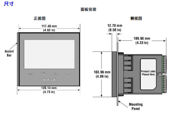
1. Installation method and size
Key requirements for installation type
Panel installation hole size: 117.40mm (width) × 120.14mm (height); The fixing ring should be tightly attached to the panel to ensure an IP65 seal
Embedded installation requires PEM nut posts (such as S0-632-6 Z1 galvanized steel); The bracket is fixed with 6 # 6-32 screws, and the front panel needs to be covered
Install through the wall with a hole of 178 × 122mm; install the heat sink vertically, leaving a ventilation space of ≥ 102mm above and below
2. Terminal wiring requirements
Input terminal:
Wire diameter: 0.0507~3.30mm ² (30~12 AWG), double wire termination ≤ 1.31mm ² (16 AWG)
Torque: 0.57Nm (5.0 lb in), wire stripping length 5.5mm
Wire/load/ground terminal:
Wire diameter: 2.5~25mm ² (14~3 AWG)
Torque: 2.7Nm (24 lb in), wire stripping length 11mm; re tighten after 48 hours, every 3-6 months
Power wiring: Terminals 98 (+) and 99 (-) should follow NEC or local electrical regulations to avoid parallel wiring with power lines
3. Installation of Elastic Module (FM)
Slot dependency rules:
The communication module (FMCA series) can only be installed in slot 6;
The high-density dual SSR module (FMHA-KAAA) requires 2 adjacent slots and cannot be placed in slots 3/6;
The module needs to be inserted with the component side facing right, and the key design prevents reverse installation.
Module identification: Confirm the part number through the black label in the lower right corner of the connector (e.g. FMMA-UKAA-AAA is 1 universal input+1 SSR output).
Input/output wiring and module specifications
1. Input wiring (some key types)
Input type wiring requires accuracy and range
Connect the negative electrode (red wire) of the thermocouple to the S terminal; The compensating wire should be made of the same alloy as the thermocouple; Input impedance>20M Ω J-type: ± 1.75 ℃ (0~750 ℃); K-type: ± 2.45 ℃ (-200~1250 ℃)
RTD (Platinum) 2-wire/3-wire, 3-wire self compensating ≤ 10 Ω lead resistance; S1 (white line) connected to R1 100 Ω (0 ℃): ± 2.00 ℃ (-200~800 ℃); 1000Ω(0℃):±2.00℃(-200~800℃)
Digital input voltage input: ≤ 36V (3mA), ≥ 3V (0.25mA) activated; Dry contact: ≤ 100 Ω activated, ≥ 500 Ω inactive update rate 10Hz; maximum short-circuit current 13mA
Current transformer input 0~50mAac; Requires Watlow 16-0246 module; The load line needs to pass through the CT in the same direction with a response time of ≤ 1 second; Accuracy ± 1mA
2. Output wiring (some key types)
Output type wiring requirements specification parameters
Mechanical relay 240Vac/30VDC, 5A resistance load; Minimum 20mA load at 24V; When connecting Quencac (0804-0147-0000) 120/240Vac across coils, a guiding power of 125VA is required; Rated load 100000 cycles
Solid state relay (SSR) 24~264Vac, 0.5A at 149 ° F (65 ℃), 1A at 50 ° F (10 ℃); only AC load optically isolated; The maximum off state leakage current is 105 μ A; 20VA guidance power at 120/240Vac
Switching DC 22~32VDC open circuit voltage; 2 output combination current ≤ 40mA; when driving external SSR, connect to DC+/DC - short circuit limit<50mA; DIN-A-MITE compatible
Universal process output 0~10Vdc (minimum load of 1k Ω) or 0~20mA (maximum load of 800 Ω); Voltage/current output accuracy of ± 15mV (voltage)/± 30 μ A (current) cannot be used simultaneously; Temperature stability 100ppm/℃
Calibration and PC connection
1. Calibration operation
Calibration prerequisite: Accurate signal source is required (such as thermocouple 0.000~50.00mV, RTD 50.0~350.0 Ω). It is recommended to first verify whether the error exceeds the specifications (such as thermocouple ± 1.75 ℃).
Operation method:
Composer software: Connect device → Device menu → Calibration → Select module/input → Enter 2 limit values as prompted;
Front panel: Menu → Service → Calibration → Select module/input → Perform on-site calibration.
Notes:
The calibration values will be reset to factory settings and cleared;
3-wire RTD calibration requires cross connection of R, T, and S inputs;
The security settings are divided into "full access/read only/no access", and without access permission, the calibration screen cannot be accessed.
2. PC connection and Composer software
- OMRON
- ABB
- General Electric
- EMERSON
- Honeywell
- HIMA
- ALSTOM
- Rolls-Royce
- MOTOROLA
- Rockwell
- Siemens
- Woodward
- YOKOGAWA
- FOXBORO
- KOLLMORGEN
- MOOG
- KB
- YAMAHA
- BENDER
- TEKTRONIX
- Westinghouse
- AMAT
- AB
- XYCOM
- Yaskawa
- B&R
- Schneider
- KONGSBERG
- NI
- WATLOW
- ProSoft
- SEW
- ADVANCED
- Reliance
- TRICONEX
- METSO
- MAN
- Advantest
- STUDER
- DANAHER MOTION
- Bently
- Galil
- EATON
- MOLEX
- DEIF
- B&W
- ZYGO
- Aerotech
- DANFOSS
- Beijer
- Moxa
- Rexroth
- Johnson
- WAGO
- TOSHIBA
- BMCM
- SMC
- HITACHI
- HIRSCHMANN
- Application field
- XP POWER
- CTI
- TRICON
- STOBER
- Thinklogical
- Horner Automation
- Meggitt
- Fanuc
- Baldor
- SHINKAWA
- Other Brands
- UniOP
- KUKA
- Iba
- Beckhoff
-
 Basler D90 96801 100 PCB Card
 -
 Basler XR2002F Voltage Regulator (110 VAC, 48-480 Hz)
 -
 Basler SR8A-2B14B3A Regulator
 -
 Basler 9561500100 Module
 -
 Basler DECS-400 BE1-11 System
 -
 Basler DECS-100-B15 Excitation Control
 -
 Basler SCP 210 Frequency Controller
 -
 Basler SR4A-2B15B3A Static Voltage Regulator
 -
 Basler BE1-32R Power Relay
 -
 Basler PIA2400-17GM Power Interface Adapter
 -
 Basler MVC 232 Manual Voltage Control Module
 -
 Basler SSR 32-12 Static Voltage Regulator
 -
 Basler 5MW AVR Generator Voltage Regulator
 -
 Basler VR63-4B Voltage Regulator
 -
 Basler DECS-100-A05 AVR for Engine Generator
 -
 Basler DECS-100-B15 Automatic Voltage Regulator
 -
 Basler BE1-32R Directional Power Relay
 -
 Basler BE1-87B Differential Relay
 -
 Basler UFOV 260A Protective Module
 -
 Basler 9-2614-02-100 PCB Rev M
 -
Basler DECS-100-B15 Digital AVR
-
 Basler 9284900103 PS DECS-400N
 -
 Basler D4N3H1U Intertie Protection
 -
 Basler DECS-100-B15 A15 AVR
 -
 Basler KR4F Voltage Regulator
 -
 Basler BE26434 T14 Transformer
 -
 Basler SR8A-2B15B3A Regulator
 -
 Westinghouse 774B472A12 AR Relay
 -
Basler DECS-100-B15 AVR
-
Basler XR2002F Regulator 110V
-
Basler SR125-E Static Regulator
-
 Basler SSR 125-12 Regulator
 -
 Basler MOC2599 Motor Pot
 -
 Basler BE1-DFPR Feeder Relay
 -
 Basler CBS 305 Current Boost
 -
 Basler BE1-25 AutoSync
 -
 Basler MVC 300 Voltage Control
 -
 Basler BE3-25A AutoSync
 -
 Basler KR7FF Static Regulator
 -
 Basler 90-49000-100 Regulator
 -
 Basler 880 kVA Dry Type Transformer Specs
 -
 Basler Electric BE1-25 Sync-Check Relay Specs
 -
 Basler SSR 125-12 Voltage Regulator Specs
 -
 Basler Electric BE1-851 Overcurrent Relay Review
 -
Basler Electric 149D930G02 Control Sub-Assembly
-
 Basler Electric BE1-81O/UT Frequency Relay Specs
 -
 Basler Electric BE1-51/27C Overcurrent Relay
 -
 Basler Electric 149D956G02 Industrial Component
 -
Basler Electric BE1-51A Overcurrent Relay Specs
-
 Basler Electric BE1-40Q Loss of Excitation Relay
 -
 Basler DECS-200 Excitation Control System
 -
 Basler DECS-200 Voltage Regulator 56-277V AC / 125V DC
 -
Basler BE1-87T Transformer Differential Relay
-
 Basler RDP-110-S1 Protection Relay
 -
 Basler BE1-700V Digital Protective Relay
 -
 Basler BE1-951 Overcurrent Protection System
 -
 Basler DECS-300 Digital Excitation Control
 -
 Basler DECS-200 Digital Excitation Control
 -
 Basler DECS-200-1C Excitation Control System
 -
Basler DECS-200-1L Digital Excitation Control
-
 Basler Electric BE1-GPS Generator Protection System
 -
Basler Electric DECS-200-1C Digital Excitation Controller
-
 Basler Electric DECS125-15 Excitation Control with Power Module
 -
 Basler Electric BE1-87G Differential Relay
 -
 Basler Electric BE1-11 Protection System I5A3M2P2N0EA00
 -
Basler Electric DECS-200-1C Excitation Control System
-
Basler Electric BE1-11g Generator Protection Relay
-
Basler Electric DECS 125-15-B2C1 V2.0.9 Excitation Control
-
 Basler Electric BE1-81O/UT3ED1JA7N2F Frequency Relay
 -
Basler Electric BE1-81O/UT3EE1YB7N1F Frequency Relay
-
 Basler Electric DECS-200-1L Digital Excitation Control System
 -
Basler DECS125-15-B2C1 Excitation Control
-
 Basler 9507900205 SSR Retrofit Voltage Regulator
 -
 Basler BE2000E Digital Voltage Regulator
 -
 Basler BE1-GPS Generator Protection System
 -
Basler DECS-250-CN1CN1N Digital Excitation Control
-
 Basler DGC-2020 Genset Controller
 -
 Basler BE1-81O UT3ED1LA7N0F Frequency Relay (Variant)
 -
 Basler BE1-81O UT3EE1YA9S0F Frequency Relay (Variant)
 -
Basler BE1-81O Over/Under Frequency Relay
-
Basler DECS125-15 Digital Excitation Control
-
Basler Electric BE1-951 Overcurrent Protection System
-
 Basler Electric BE1-700V Digital Protective Relay
 -
 Basler Electric APR63-5 Automatic Voltage Regulator
 -
Basler Electric BE1-851 Overcurrent Protection System
-
Basler Electric DECS-250-LN1SN1N Excitation Control
-
 Basler Electric BE1-87T Transformer Differential Relay
 -
Basler Electric DECS-200-1L Excitation Control System
-
 Basler Electric 9310300100 DECS-300 Excitation Control
 -
 Basler Electric SSE-N 125-4.5KW Shunt Exciter Regulator
 -
 Basler Electric DGC-2020HD-5NS1DNSBA Genset Controller
 -
Basler Electric BE1-81-O/UT3EE1JB7N1F Frequency Relay
-
Basler Electric BE1-81T1EE1WA0N1F Frequency Relay
-
 Basler Electric BE1-25M1EA6PN5R1F Sync-Check Relay
 -
 Basler Electric BE1-GPS Generator Protection System
 -
Basler Electric DECS-250-LN1SN1N Excitation Control Rev V
-
 Basler Electric DECS-250-CN2CN1N Excitation Control
 -
Basler Electric BE1-50/51B-207 Overcurrent Relay
-
Basler Electric DECS-300-C0N0 Excitation Control System
-
Basler Electric DECS-200 Digital Excitation Control System
-
Basler Electric DECS-250-LN1CN1N Excitation Unit
-
Basler Electric DECS-250 LN2SA1D Excitation Unit Specs
-
Basler Electric BE1-87T Transformer Relay Review
-
Basler Electric BE1-11 Protection System
-
Basler Electric BE1-GPS100-E4N1H1N Protection System
-
 Allen-Bradley 442G-MABH-R Safety Module
 -
 Beckhoff CX1030-0111 PLC Assembly Profile
 -
 FANUC IC693CPU364 PLC Module
 -
 Orange Denmark Type 200816 220 PLC Specs
 -
 OMRON C200H-SNT31 Sysmac PLC Module
 -
 Allen Bradley 20AB022A3AYNANC0 PowerFlex 70
 -
 OMRON C200HW-PCU01 Position Control Unit
 -
 ABB AO845A-eA Analog Output Module
 -
 OMRON CJ1M-CPU22 CPU Unit
 -
 Allen Bradley 100-E265ED11 Contactor
 -
 Honeywell 51304511-100 Interface Module
 -
 SOLEXY BXF3S0101N0018 Gateway Module
 -
 OMRON CJ2H-CPU65 CPU Unit
 -
 Automation Direct GS2-45P0 AC Drive
 -
 M68-2000 2-Axis Motion CNC Controller
 -
 OMRON CJ1M-CPU11 V3.0 PLC CPU Unit
 -
 OMRON CJ1W-NC413 4-Axis Positioning Controller
 -
 OMRON 3G2A3-PRO16 Programming Console HMI
 -
 Siemens 3VT8440-2AA04-2GA2 Molded Case Circuit Breaker
 -
 Siemens 3RT5045 Contactor Series
 -
 OMRON C200HS-CPU01-E SYSMAC PLC Controller
 -
 OMRON C500-NC103-E Positioning Control Unit
 -
 OMRON CJ1W-TC001 Temperature Control Unit


