
Foxboro Evo FBM217 Discrete Input Module
Foxboro Evo FBM217 Discrete Input Module
Core functions and features of the module
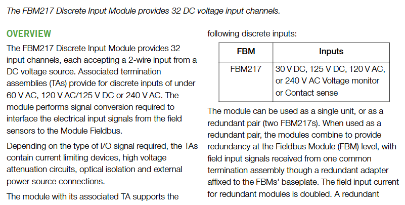
FBM217 is a 32 channel discrete input module designed specifically for industrial environments, supporting multi voltage level signal acquisition and high reliability operation. Its core functions and features are as follows:
(1) Core functions
Multi voltage signal support: covering low, medium, and high voltage inputs, including:
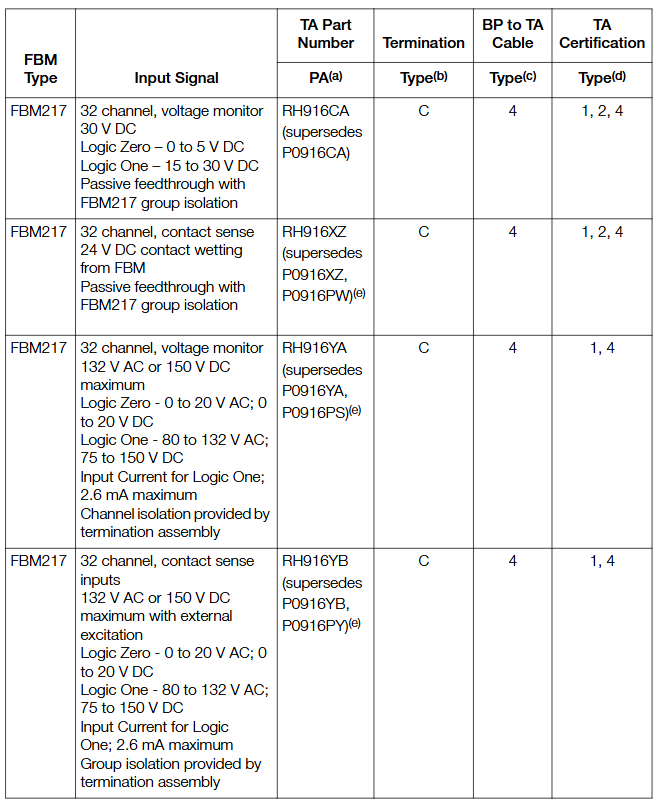
Low voltage: 15~60V DC (voltage monitoring or contact detection);
Medium voltage: 120V AC/125V DC (logic 0:0~20V AC/DC, logic 1:80~132V AC/75~150V DC);
High voltage: 240V AC (logic 0:0~40V AC, logic 1:164~264V AC).
Redundancy deployment capability: Supports single module or redundant paired deployment (2 FBM217s need to be installed in adjacent odd/even positions on the base, with the redundant adapter RH926ZY). In redundancy mode, the input signal quality is verified through the CINR function block of Foxboro Evo control software, and the optimal signal is automatically selected.
Event Sequence (SOE) Function: In conjunction with I/A Series v8. x and above software or Control Core Services v9.0+, supports event collection, storage, and reporting, with optional GPS time synchronization (accuracy up to 1ms); The old version software (before v8. x) needs to be implemented through the ECB6/EVENT block, with an accuracy of 1 second and no cross processor synchronization.
Signal conditioning and protection: relying on termination components (TAs) to achieve optical isolation, current limitation, and voltage attenuation. Some TAs support external excitation power supply access without the need for additional on-site circuit protection equipment (such as fuses).
(2) Key characteristics
Environmental adaptability: Complies with ISA S71.04 G3 level harsh environmental standards, can withstand vibration (0.75 m/S ² @ 5-500Hz), wide temperature range (working -20~70 ℃, storage -40~70 ℃);
Hot swappable design: When replacing modules, there is no need to remove on-site wiring, power or communication cables. The replacement of redundant modules does not affect the on-site signal acquisition of normal modules;
Status indication: The front LED light provides real-time feedback on the operating status of the module (such as fault, ready) and the discrete status of a single input channel, facilitating quick diagnosis;
Communication reliability: Connected to the Fieldbus Communication Module (FCM) or Control Processor (FCP) via a 2 Mbps module fieldbus, supporting A/B dual path communication and automatic switching in case of single path failure.
Hardware parameters and technical specifications
(1) Input and electrical parameters
Parameter category specific specifications
Channel configuration with 32 isolated channels (isolation level dependent on TA, some TAs support channel level isolation)
Typical 2.2mA at 30V DC input current; maximum 2.8mA at high voltage (240V AC) (logic 1 state)
Source resistance limit logic 1 (15V DC) ≤ 1k Ω; logic 0 (30V DC) ≥ 100k Ω
The filtering/debounce time can be configured (no filtering, 4ms, 8ms, 16ms, 32ms, firmware v1.25H+required)
Maximum pulse counting rate 250Hz
The combination of isolation voltage module and TA can withstand 600V AC (1 minute, group isolation channel to ground)
(2) Power supply and power consumption
Power input: 24V DC (redundant mode, allowable range+5%/-10%, i.e. 21.6-26.4V DC);
Power consumption: maximum 3W at 24V DC (operation), maximum heat dissipation 5W;
Power protection: Supports redundant independent DC power supply access to enhance power supply reliability.
(3) Physical and environmental parameters
Parameter category specification requirements
Dimensions (module) Height 102mm (including installation ears 114mm) x Width 45mm x Depth 104mm
The weight module weighs approximately 284g (10oz); TA approximately 420-454g (0.93-1.0lb)
Working environment temperature -20~70 ℃, humidity 5%~95% (non condensing), altitude -300~3000m
Storage environment temperature -40~70 ℃, humidity 5%~95% (no condensation), altitude -300~12000m
The pollution level complies with EIA 364-65 Class III and is suitable for harsh environments of ISA S71.04 G3 level
Installation and Termination Component (TA) Configuration
FBM217 needs to be used in conjunction with a dedicated base and termination assembly (TA), and installation and wiring must follow strict specifications. The core requirements are as follows:
(1) Base and installation
Base type: Modular base (DIN rail or 19 inch rack mounted), with a maximum capacity of 4 or 8 FBM modules per base;
Redundant modules need to be installed in adjacent odd/even positions (such as 1&2, 3&4) and connected through redundant adapter RH926ZY;
Support 100 series conversion installation structure (refer to PSS 31H-2W8) for easy upgrading of old systems.
Installation specifications:
DIN rail: Supports 32mm/35mm specifications, with priority given to galvanized yellow chromium steel material (ensuring good grounding), fixed at a spacing of approximately 200mm;
Panel installation: Use M4 or # 8 screws and reserve heat dissipation space (≥ 25mm on each side of the module).
(2) Termination Component (TA) Selection
- OMRON
- ABB
- General Electric
- EMERSON
- Honeywell
- HIMA
- ALSTOM
- Rolls-Royce
- MOTOROLA
- Rockwell
- Siemens
- Woodward
- YOKOGAWA
- FOXBORO
- KOLLMORGEN
- MOOG
- KB
- YAMAHA
- BENDER
- TEKTRONIX
- Westinghouse
- AMAT
- AB
- XYCOM
- Yaskawa
- B&R
- Schneider
- KONGSBERG
- NI
- WATLOW
- ProSoft
- SEW
- ADVANCED
- Reliance
- TRICONEX
- METSO
- MAN
- Advantest
- STUDER
- DANAHER MOTION
- Bently
- Galil
- EATON
- MOLEX
- DEIF
- B&W
- ZYGO
- Aerotech
- DANFOSS
- Beijer
- Moxa
- Rexroth
- Johnson
- WAGO
- TOSHIBA
- BMCM
- SMC
- HITACHI
- HIRSCHMANN
- Application field
- XP POWER
- CTI
- TRICON
- STOBER
- Thinklogical
- Horner Automation
- Meggitt
- Fanuc
- Baldor
- SHINKAWA
- Other Brands
- UniOP
- KUKA
- Iba
- Beckhoff
-
 OMRON C60H C6DR DE V1 Sysmac PLC
 -
 MITSUBISHI ELECTRIC A2ACPU21 S1 CPU Module
 -
 ABB BAILEY INNPM12 Network Process Module
 -
 HONEYWELL 620 0073C IPC PLC Module
 -
 Mitsubishi 15050 PR02B PLC Circuit Board
 -
 SIEMENS 6SY7000 0AC37 Drive Control Module
 -
 OMRON TJ2 ECT16 Traxial EtherCAT Controller
 -
 GE Fanuc IC698PSD300D Power Supply Module
 -
 Texas Instruments Series 505 16 Position Base
 -
 OMRON YASKAWA SGDH 10DE OY Servo Drive
 -
 Allen‑Bradley 440G-MT Safety Interlock Switch Specs
 -
 Rubycon PD27A 24V 8A Power Supply Module
 -
 SK-H1-GDB1-F11D PLC Gate Driver Board Kit
 -
 VIPA 441-4UA14 451-4UA14 PLC Module Rack
 -
 Mitsubishi FX5U-80MT ESS PLC Controller Specs
 -
 Mitsubishi Q64TCRTN Temperature PLC Module
 -
 GE 1C31170G Rev10 PLC Circuit Board Module
 -
 Schneider TWDLMDA40DTK PLC Controller Module
 -
 Omron FQM1-MMA22 Motion Control Module Specs
 -
 OMRON CJ1W-NCF71 Position Control Unit Specs
 -
 Schneider TSXETY4103 Ethernet Module
 -
 Mitsubishi Q12PHCPU Process CPU
 -
 Yaskawa 3G3HV-A4022-CE AC Drive
 -
 Cincinnati Milacron 3-533-0669G Temperature Control Board
 -
 Allen Bradley 20AC030A3AYNANC0 PowerFlex 70 Drive
 -
 Siemens 6ES7314-6BG03-0AB0 CPU 314C-2 DP
 -
 Carrier 17EX54007903 PLC Module
 -
 OMRON CS1W-V600C12 ID Controller Module
 -
 Honeywell 51402755-100 PCB Card
 -
 Heidenhain ECN 113 Rotary Encoder
 -
 OMRON B7AM-8B16 I/O Terminal Block
 -
 Fanuc A06B-6110-H026 Power Supply Module
 -
 Schneider TSXETG3021 Ethernet Gateway
 -
 OMRON CS1W-CLK21-V1 Controller Link Unit
 -
 NP1W6406T-Z704 PLC I/O Module
 -
 OMRON CJ1W-DA08C Analog Output Module
 -
 Yaskawa 3G3HV-A4022-CE AC Drive
 -
 OMRON NB7W-TW01B CP1L-EL20DR-D Power Panel
 -
 OMRON C500-NC103-E Position Control Unit
 -
 Steag Hamatech PLC DCS Servo Control System
 -
 Siemens 6SN1123-1AA00-0DA1 Power Supply Module
 -
 GE IC693CHS391H CPU & AD693CMM301A PLC Module
 -
 Siemens 6FC5303-0AF23-1AA1 PLC Control Panel
 -
 Square D CM4000T PowerLogic Circuit Monitor J1 F16
 -
 Siemens 6FX5002-5DG10-1BA0 MOTION-CONNECT 500 Cable
 -
 Schmersal SRB324ST 101195504 Safety Relay 24V
 -
 Mitsubishi 15050-PR02A PLC Circuit Board Module
 -
 OMRON CQM1-AD041 Analog Input PLC Module
 -
 Beckhoff EL5042 EtherCAT PLC Terminal Module
 -
 OMRON C200HW-MC402-E Motion Control Unit
 -
 C36TC0UA1100 Industrial Temperature Controller
 -
 NL8048BC24 12 Industrial Control LCD Module
 -
 OMRON R88D Servo Drive and Motor System
 -
 OMRON CS1W CLK21 V1 Controller Link Module
 -
 OMRON YASKAWA R7M A20030 S1 D Servo Motor
 -
 SIEMENS 6AV2128 3KB06 0AX1 Unified Comfort Panel
 -
 Schneider Electric METSEPM8240 PowerLogic Meter
 -
 Advanced AMCI 1PLC 1 31F Programmable Limit Switch
 -
 ABB PM582 ETH Programmable Logic Processor
 -
 SIEMENS 6FC5110 0CB01 0AA0 CPU Control Board
 -
 Schleicher P03GS13A CPU Module
 -
 Siemens 6SN1123-1AA00-0BA1 Power Module
 -
 Mitsubishi A1S61PN Power Supply Module
 -
 Yaskawa CPS-IONB DC Power Supply Module
 -
 Siemens 6ES7215-2BD00 CPU 215-2
 -
 Mitsubishi A2ACPU MELSEC PLC System Kit
 -
 ProSoft 3150-MCM Communication Module
 -
 Mitsubishi OSE104ET Incremental Encoder
 -
 OMRON CJ1W-AD081-V1 Analog Input Module
 -
 Broadcom BCM5464A1KRB Quad Port Ethernet IC
 -
 Modicon M221-24IO TM221C24 PLC 24 PNP Transistor
 -
 Allen-Bradley 1321-3R160-B Line Reactor 3R160B
 -
 Beckhoff CX1020-0012 Embedded PLC Module Specs
 -
 Turck BL20-PF-24VDC-D Power Feed Module Specs
 -
 Siemens 6SY7000-0AC37 Power Supply Module
 -
 Yaskawa SGDH-10DE-OY 1kW 400V Servo Drive Specs
 -
 Omron 3G3SV-BB015-E 1.5kW 220V VFD Specs
 -
 Uni-Pro CPU91-PLC J 23.020167X Processor Module
 -
 PASABAN MTC-3044 PLC Rack Power Supply 4835-A
 -
 XYCOM 3015T Operator Interface Panel BIN4.4.4
 -
 OMRON CJ1W-MD261 Mixed I/O Module
 -
 Omron NJ301-1100 PLC CPU eCat EIP Specs
 -
 Omron F500-C15-ETN Vision System PLC Module
 -
 Modicon M241-24IO TM/T2UK PLC with Ethernet
 -
 SIXNET YS-800-001 RTU PLC Module
 -
 BEMAC UST-202-D Interface Board 1307D V08B2
 -
 Yaskawa JANCD-MMOIC-02 Drive Circuit Board
 -
 ABB 3BSE005028R1 SDCS-COM-1 Comm Board
 -
 Omron 3G3MX2-A4110 A4150 Inverter Drives Specs
 -
 KEYENCE CA-E100 PLC Module
 -
 GE IC693ALG223-GB Analog Input Module Specs
 -
 ABB BAILEY IMMFP01 Multi Function Processor System
 -
 SIEMENS 6FC5372 0AA00 0AA1 NCU 7202 Controller
 -
Modicon TM241CE4 40I O Transistor Programmable Controller
-
 SIEMENS 6ES7 315 2EH13 0AB0 CPU 3152 PN DP
 -
 NORIS A1 91 PCB Card Rack Module System
 -
 SIEMENS 6ES7 313 5BE01 0AB0 Compact CPU
 -
 SCHNEIDER ELECTRIC S144B MICROLOGIC 60A Trip Unit
 -
 CNI PLC269 v3 Control Module Board Rev H
 -
ABB BAILEY IIMCP02 Processor Module
-
 OMRON NT20S ST121 EV3 Operator Interface Terminal
 -
 OMRON NS-CA001 Video Input Unit
 -
 GE Fanuc IC695CHS012 RX3i Backplane
 -
 Allen Bradley 2711E-K14C6 PanelView 1400e Terminal
 -
 Siemens Sinamics CCB 10000432.71 Power Cell
 -
 Siemens 6SL3210-1SE21-8UA0 Power Module PM340
 -
 Yaskawa CIMR-F7A20P4 AC Drive
 -
 Beckhoff EP1918-0002 EtherCAT Box I/O Module
 -
 OMRON CQM1-TC001 Temperature Control Module
 -
 GE Fanuc SGHA36AT0400 Industrial Contactor
 -
 OMRON NJ501-1500 PLC Machine Automation Controller
 -
 Mitsubishi MAZAK QX084 Power Supply MELDAS 500 CNC
 -
 B&R 0AC808.9 PLC Automation Module
 -
 OMRON CP1H-XA40DT1-D PLC Module
 -
 G&W Electric PLC15 5111 011 15kV Capnut Assembly
 -
 GE DS200SLCCG3AGH PCB Circuit Board
 -
 Siemens SINUMERIK 6FC3981-4FD PLC Extension
 -
 OMRON F300-DC I/O Image Processing Unit
 -
 FANUC A06B-0314-B002 AC Servo Motor
 -
 GC-S84 Programmable Controller Logic Module
 -
 PASABAN MONTELEC MTC3001-DC Drive Control PLC
 -
 Allen Bradley 100E460EJ11 Auxiliary Contactor
 -
 Bosch Rexroth 1070075337-101 Card Parameters
 -
 HMS Anybus AB7646-F Gateway Specifications
 -
 Bosch 062633-303401 CNC Servo PLC Card
 -
 TI 500-5023 Series PLC Power Supply
 -
 Siemens C98043-A7002-L1-12 Circuit Board
 -
 Omron E5CC-RX3A5M-000 Controller


