
Foxboro Evo FBM237 Analog Output Module
Foxboro Evo FBM237 Analog Output Module
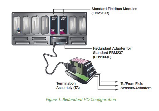
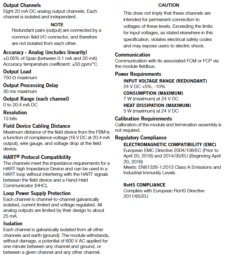
The FBM237 contains eight 0-20 mA analog output channels. In situations where control system reliability is important, the FBM237 may have a redundant module installed. This permits all eight outputs to maintain operation in the presence of a single fault and during the time that the suspect module is removed and replaced. The 0-20 mA signals are electrically compatible with HART ® field devices.
FEATURES
PHYSICAL DESIGN
REDUNDANT ANALOG OUTPUTS
HIGH RELIABILITY
The redundancy of the module pair, coupled with the high coverage of faults, provides a very high subsystem availability time.
Either module in the redundant pair may be replaced without upsetting field output signals to the good module. The module can be removed/replaced without removing field device termination cabling,power, or communications cabling.
FIELDBUS COMMUNICATION
A Fieldbus Communications Module or a Control Processor interfaces to the redundant 2 Mbps module Fieldbus used by the FBMs. The FBM237 accepts communication from either path (A or B) of the 2 Mbps Fieldbus — should one path fail or be switched at the system level, the module continues communication over the active path.
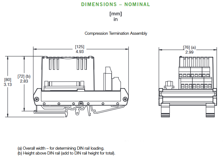
The module mounts on the Standard Modular baseplate, which accommodates up to eight Fieldbus Modules. The Modular baseplate is either DIN rail mounted or rack mounted, and includes signal connectors for redundant Fieldbus, redundant independent DC power, and termination cables.
Redundant modules must be located in adjacent odd/even position pairs on the baseplate (positions 1 and 2, 3 and 4, 5 and 6, or 7 and 8). To achieve the redundant output, a redundant adapter module is placed on the two adjacent baseplate termination cable connectors to provide a single termination
Key Features
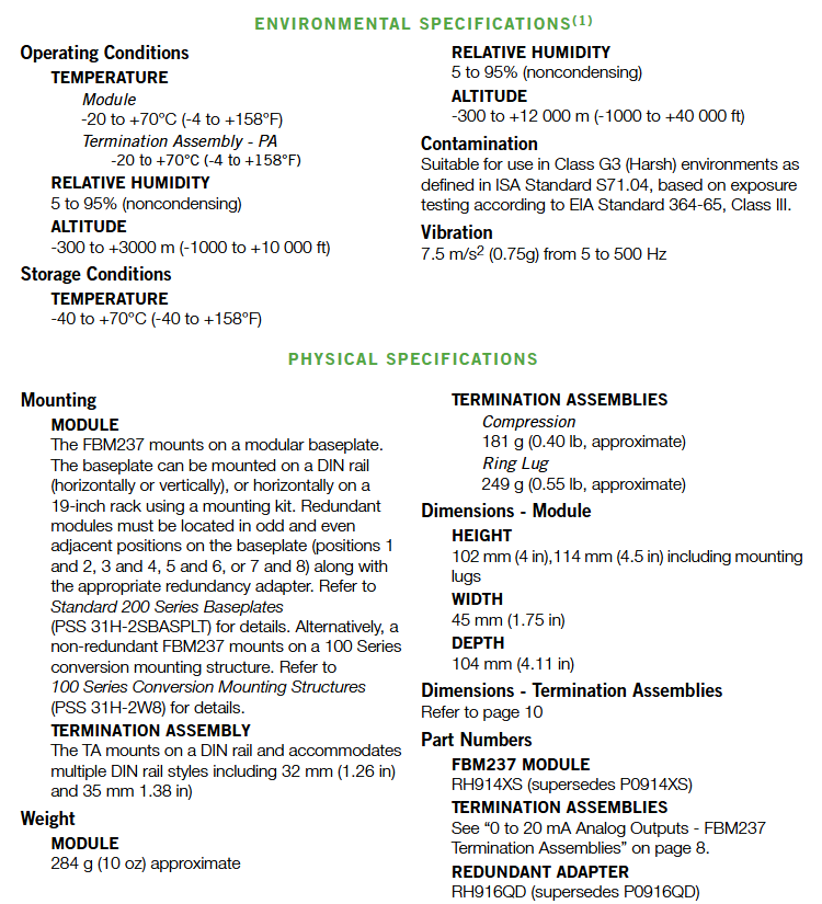
Environmental adaptability: Complies with ISA S71.04 G3 level harsh environmental standards, can withstand vibration (0.75g @ 5-500Hz), wide temperature range (working -20~70 ℃, storage -40~70 ℃), and is suitable for industrial high temperature and high dust scenes;
Hot plugging and maintenance: Module replacement does not require dismantling of on-site wiring, power or communication cables, and redundant module maintenance does not affect the operation of on-site equipment; Partial termination components (TA) with bypass sockets, supporting temporary output maintenance through bypass stations (such as P0900HJ);
Status indication: The front LED light provides real-time feedback on the communication status, power status, and channel faults of the module, making it easy to quickly locate problems;
Communication reliability: Connected to the fieldbus communication module (FCM) or control processor (FCP) through a 2 Mbps redundant fieldbus, supporting A/B dual path switching, and ensuring uninterrupted data transmission in case of single path failure.
Hardware parameters and technical specifications
(1) Output and precision parameters
Parameter category specific specifications
Channel configuration includes 8 independent channels, with each channel being Galvanically isolated (between channels, channel to ground)
Accuracy (including linearity) ± 0.05% range (within the range of 0.1~20mA), temperature coefficient ± 50 ppm/℃ (temperature changes have little impact on accuracy)
Maximum output delay of 30ms (meets the real-time requirements of most industrial controls)
Resolution of 13 bits (high output adjustment accuracy, supports fine control signal output)
Circuit power supply protection with independent current limitation and voltage regulation for each channel to avoid overload damage
The wiring distance depends on the compliant voltage (18V DC at 20.4mA), wire specifications, and equipment voltage drop, and supports a maximum of 30m cables
(2) Power supply and power consumption
Power input: 24V DC (redundant mode, allowable range+5%/-10%, i.e. 21.6-26.4V DC), requires independent redundant power supply;
Power consumption: Maximum 7W (running) at 24V DC, maximum heat dissipation of 5W, reserved heat dissipation space is required to avoid module overheating.
(3) Physical and environmental parameters
Parameter category specification requirements
Dimensions (module) height 102mm (including installation ears 114mm) x width 45mm x depth 104mm, single slot design
The weight module weighs approximately 284g (10oz); TA approximately 181-249g (0.40-0.55lb, depending on terminal type)
Working environment temperature -20~70 ℃, humidity 5%~95% (non condensing), altitude -300~3000m
Storage environment temperature -40~70 ℃, humidity 5%~95% (no condensation), altitude -300~12000m
The pollution level complies with EIA 364-65 Class III and is suitable for harsh environments with ISA S71.04 G3 level (high dust, high humidity)
Installation and Termination Component (TA) Configuration
FBM237 needs to be used in conjunction with a dedicated base, termination assembly (TA), and cables. Installation and wiring must follow strict specifications, with the following core requirements:
(1) Base and installation
Base type:
Modular base: Supports DIN rail (32mm/35mm) or 19 inch rack installation, with a maximum capacity of 8 FBM modules per base;
Redundant installation: Redundant modules need to be fixed in adjacent odd/even positions, connected to the base terminals through the redundant adapter RH916QD, to achieve two modules sharing one TA signal interface.
Installation specifications:
Heat dissipation space: Reserve ≥ 25mm space on each side of the module to avoid the influence of adjacent devices on heat dissipation;
Grounding requirements: Galvanized yellow chromium steel DIN rails are preferred for the base to ensure reliable grounding, and aluminum/plastic rails are prohibited (which may cause poor grounding).
(2) Termination Component (TA) Selection
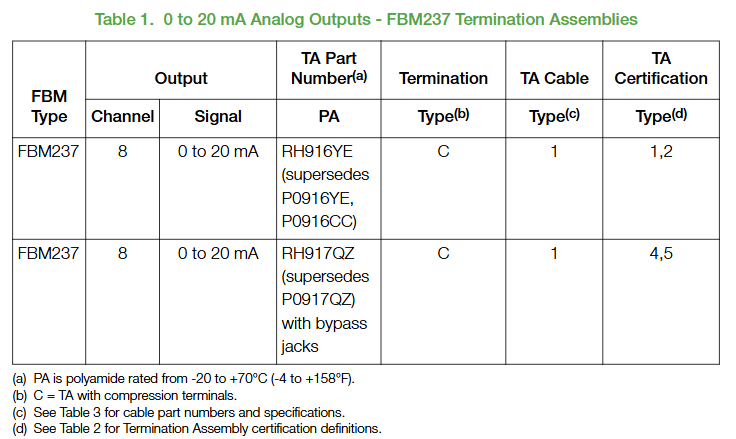
TA is a key component connecting FBM237 with on-site actuators, providing signal switching and bypass maintenance functions. It needs to be selected according to the scenario, and the specific model and adaptation scenario are as follows:
TA model core function adaptation scenario authentication type
RH916YE (main TA) 8-channel signal transfer, no bypass function, normal scenario (no online maintenance required) Type 1/2 (compatible with hazardous areas)
RH917QZ (main TA) 8-channel with bypass socket, supporting bypass station access to critical scenarios (requiring online maintenance, such as chemical reaction kettle) Type 4/5 (ordinary area+Class 2 circuit)
TA connection: TA connects to the base through a Type 1 cable (25 pin D-sub interface), with a maximum cable length of 30m, supporting 2 materials:
P/PVC: polyurethane outer layer+PVC insulation, temperature range -20~80 ℃, suitable for ordinary industrial environments;
LSZH (Low Smoke Zero Halogen): Low smoke zero halogen release at high temperatures, suitable for enclosed environments such as ships and subways, with a temperature range of -40~105 ℃;
Wiring specifications: TA supports solid/multi strand wires of 0.2~4mm ² (24~12 AWG), and multi strand wires with wire ears should be 0.2~2.5mm ² (with or without plastic sleeves), with terminal torque in accordance with manufacturer specifications.
Compliance certification and security requirements
(1) Core certification
The FBM237 module and its supporting TA comply with global safety, electromagnetic compatibility, and environmental standards in multiple regions, with the following core certifications:
Specific standards and levels for certification categories
Hazardous Area Certification North America: UL/UL-C Class I Division 2 Groups A-D, Temperature Code T4;
Europe: ATEX 2014/34/EU II 3 G Ex nA IIC T4 (DEMKO certification, except RH917QZ);
International: Compliant with IECEx standards and suitable for Zone 2 hazardous areas
Electromagnetic Compatibility (EMC) EU EMC Directive 2014/30/EU, compliant with EN 61326-1:2013 Class A (Emission and Immunity in Industrial Environments)
Low Voltage Safety EU Low Voltage Directive 2014/35/EU, communication circuits comply with UL Class 2 standards (NFPA 70 Article 725, CSA C22.1 Section 16)
Environmental compliance complies with the EU RoHS 2011/65/EU directive, restricting the use of harmful substances such as lead and mercury
Ship certification ABS type approval, French Classification Society (BV) EC31 environmental category certification, applicable to ship automation systems
(2) Safety operation requirements
Electrical safety:
Isolation restriction: Although the module can withstand 600V AC, it is prohibited to connect to excessive voltage (such as 220V AC) for a long time to avoid insulation damage;
Wiring specifications: On site wiring should distinguish between positive and negative poles. In redundancy mode, ensure that the two modules have independent power supplies to prevent redundancy failure caused by single point power failure.
Dangerous area operation:
Shell requirements: It must be installed in a certified shell with a protection level of IP54 or above, and the shell must be opened with tools to prevent unauthorized operation;
Maintenance process: Power off or confirm that the area is in a non hazardous environment before connecting/disconnecting cables. Redundant module replacement should be carried out after the faulty module is powered off.
Upgrade and compatibility instructions
FBM237 is mainly used to replace the Foxboro 100 series FBM37 analog output module. When upgrading, the following compatibility points should be noted:
Hardware replacement: A single FBM237 can directly replace one FBM37, and on-site wiring can be reused in two ways:
Direct adaptation: Use the documentation to specify the TA (such as RH916YE) and rewire it to the TA terminal;
Adapter reuse: Connect the terminated component adapter (TAA, refer to PSS 31H-2W4) directly to the original FBM37 wiring without rewiring.
Software adaptation:
Should be paired with Foxboro Evo control software v8. x+or Control Core Services v9.0+, supporting AOUTR redundant function block configuration;
The failure safety parameters need to be pre-set in the software (such as a fallback current of 0mA and a fault delay time) to ensure that the actuator is in a safe state in case of a fault.
- OMRON
- ABB
- General Electric
- EMERSON
- Honeywell
- HIMA
- ALSTOM
- Rolls-Royce
- MOTOROLA
- Rockwell
- Siemens
- Woodward
- YOKOGAWA
- FOXBORO
- KOLLMORGEN
- MOOG
- KB
- YAMAHA
- BENDER
- TEKTRONIX
- Westinghouse
- AMAT
- AB
- XYCOM
- Yaskawa
- B&R
- Schneider
- KONGSBERG
- NI
- WATLOW
- ProSoft
- SEW
- ADVANCED
- Reliance
- TRICONEX
- METSO
- MAN
- Advantest
- STUDER
- DANAHER MOTION
- Bently
- Galil
- EATON
- MOLEX
- DEIF
- B&W
- ZYGO
- Aerotech
- DANFOSS
- Beijer
- Moxa
- Rexroth
- Johnson
- WAGO
- TOSHIBA
- BMCM
- SMC
- HITACHI
- HIRSCHMANN
- Application field
- XP POWER
- CTI
- TRICON
- STOBER
- Thinklogical
- Horner Automation
- Meggitt
- Fanuc
- Baldor
- SHINKAWA
- Other Brands
- UniOP
- KUKA
- Iba
- Beckhoff
-
 OMRON C60H C6DR DE V1 Sysmac PLC
 -
 MITSUBISHI ELECTRIC A2ACPU21 S1 CPU Module
 -
 ABB BAILEY INNPM12 Network Process Module
 -
 HONEYWELL 620 0073C IPC PLC Module
 -
 Mitsubishi 15050 PR02B PLC Circuit Board
 -
 SIEMENS 6SY7000 0AC37 Drive Control Module
 -
 OMRON TJ2 ECT16 Traxial EtherCAT Controller
 -
 GE Fanuc IC698PSD300D Power Supply Module
 -
 Texas Instruments Series 505 16 Position Base
 -
 OMRON YASKAWA SGDH 10DE OY Servo Drive
 -
 Allen‑Bradley 440G-MT Safety Interlock Switch Specs
 -
 Rubycon PD27A 24V 8A Power Supply Module
 -
 SK-H1-GDB1-F11D PLC Gate Driver Board Kit
 -
 VIPA 441-4UA14 451-4UA14 PLC Module Rack
 -
 Mitsubishi FX5U-80MT ESS PLC Controller Specs
 -
 Mitsubishi Q64TCRTN Temperature PLC Module
 -
 GE 1C31170G Rev10 PLC Circuit Board Module
 -
 Schneider TWDLMDA40DTK PLC Controller Module
 -
 Omron FQM1-MMA22 Motion Control Module Specs
 -
 OMRON CJ1W-NCF71 Position Control Unit Specs
 -
 Schneider TSXETY4103 Ethernet Module
 -
 Mitsubishi Q12PHCPU Process CPU
 -
 Yaskawa 3G3HV-A4022-CE AC Drive
 -
 Cincinnati Milacron 3-533-0669G Temperature Control Board
 -
 Allen Bradley 20AC030A3AYNANC0 PowerFlex 70 Drive
 -
 Siemens 6ES7314-6BG03-0AB0 CPU 314C-2 DP
 -
 Carrier 17EX54007903 PLC Module
 -
 OMRON CS1W-V600C12 ID Controller Module
 -
 Honeywell 51402755-100 PCB Card
 -
 Heidenhain ECN 113 Rotary Encoder
 -
 OMRON B7AM-8B16 I/O Terminal Block
 -
 Fanuc A06B-6110-H026 Power Supply Module
 -
 Schneider TSXETG3021 Ethernet Gateway
 -
 OMRON CS1W-CLK21-V1 Controller Link Unit
 -
 NP1W6406T-Z704 PLC I/O Module
 -
 OMRON CJ1W-DA08C Analog Output Module
 -
 Yaskawa 3G3HV-A4022-CE AC Drive
 -
 OMRON NB7W-TW01B CP1L-EL20DR-D Power Panel
 -
 OMRON C500-NC103-E Position Control Unit
 -
 Steag Hamatech PLC DCS Servo Control System
 -
 Siemens 6SN1123-1AA00-0DA1 Power Supply Module
 -
 GE IC693CHS391H CPU & AD693CMM301A PLC Module
 -
 Siemens 6FC5303-0AF23-1AA1 PLC Control Panel
 -
 Square D CM4000T PowerLogic Circuit Monitor J1 F16
 -
 Siemens 6FX5002-5DG10-1BA0 MOTION-CONNECT 500 Cable
 -
 Schmersal SRB324ST 101195504 Safety Relay 24V
 -
 Mitsubishi 15050-PR02A PLC Circuit Board Module
 -
 OMRON CQM1-AD041 Analog Input PLC Module
 -
 Beckhoff EL5042 EtherCAT PLC Terminal Module
 -
 OMRON C200HW-MC402-E Motion Control Unit
 -
 C36TC0UA1100 Industrial Temperature Controller
 -
 NL8048BC24 12 Industrial Control LCD Module
 -
 OMRON R88D Servo Drive and Motor System
 -
 OMRON CS1W CLK21 V1 Controller Link Module
 -
 OMRON YASKAWA R7M A20030 S1 D Servo Motor
 -
 SIEMENS 6AV2128 3KB06 0AX1 Unified Comfort Panel
 -
 Schneider Electric METSEPM8240 PowerLogic Meter
 -
 Advanced AMCI 1PLC 1 31F Programmable Limit Switch
 -
 ABB PM582 ETH Programmable Logic Processor
 -
 SIEMENS 6FC5110 0CB01 0AA0 CPU Control Board
 -
 Schleicher P03GS13A CPU Module
 -
 Siemens 6SN1123-1AA00-0BA1 Power Module
 -
 Mitsubishi A1S61PN Power Supply Module
 -
 Yaskawa CPS-IONB DC Power Supply Module
 -
 Siemens 6ES7215-2BD00 CPU 215-2
 -
 Mitsubishi A2ACPU MELSEC PLC System Kit
 -
 ProSoft 3150-MCM Communication Module
 -
 Mitsubishi OSE104ET Incremental Encoder
 -
 OMRON CJ1W-AD081-V1 Analog Input Module
 -
 Broadcom BCM5464A1KRB Quad Port Ethernet IC
 -
 Modicon M221-24IO TM221C24 PLC 24 PNP Transistor
 -
 Allen-Bradley 1321-3R160-B Line Reactor 3R160B
 -
 Beckhoff CX1020-0012 Embedded PLC Module Specs
 -
 Turck BL20-PF-24VDC-D Power Feed Module Specs
 -
 Siemens 6SY7000-0AC37 Power Supply Module
 -
 Yaskawa SGDH-10DE-OY 1kW 400V Servo Drive Specs
 -
 Omron 3G3SV-BB015-E 1.5kW 220V VFD Specs
 -
 Uni-Pro CPU91-PLC J 23.020167X Processor Module
 -
 PASABAN MTC-3044 PLC Rack Power Supply 4835-A
 -
 XYCOM 3015T Operator Interface Panel BIN4.4.4
 -
 OMRON CJ1W-MD261 Mixed I/O Module
 -
 Omron NJ301-1100 PLC CPU eCat EIP Specs
 -
 Omron F500-C15-ETN Vision System PLC Module
 -
 Modicon M241-24IO TM/T2UK PLC with Ethernet
 -
 SIXNET YS-800-001 RTU PLC Module
 -
 BEMAC UST-202-D Interface Board 1307D V08B2
 -
 Yaskawa JANCD-MMOIC-02 Drive Circuit Board
 -
 ABB 3BSE005028R1 SDCS-COM-1 Comm Board
 -
 Omron 3G3MX2-A4110 A4150 Inverter Drives Specs
 -
 KEYENCE CA-E100 PLC Module
 -
 GE IC693ALG223-GB Analog Input Module Specs
 -
 ABB BAILEY IMMFP01 Multi Function Processor System
 -
 SIEMENS 6FC5372 0AA00 0AA1 NCU 7202 Controller
 -
Modicon TM241CE4 40I O Transistor Programmable Controller
-
 SIEMENS 6ES7 315 2EH13 0AB0 CPU 3152 PN DP
 -
 NORIS A1 91 PCB Card Rack Module System
 -
 SIEMENS 6ES7 313 5BE01 0AB0 Compact CPU
 -
 SCHNEIDER ELECTRIC S144B MICROLOGIC 60A Trip Unit
 -
 CNI PLC269 v3 Control Module Board Rev H
 -
ABB BAILEY IIMCP02 Processor Module
-
 OMRON NT20S ST121 EV3 Operator Interface Terminal
 -
 OMRON NS-CA001 Video Input Unit
 -
 GE Fanuc IC695CHS012 RX3i Backplane
 -
 Allen Bradley 2711E-K14C6 PanelView 1400e Terminal
 -
 Siemens Sinamics CCB 10000432.71 Power Cell
 -
 Siemens 6SL3210-1SE21-8UA0 Power Module PM340
 -
 Yaskawa CIMR-F7A20P4 AC Drive
 -
 Beckhoff EP1918-0002 EtherCAT Box I/O Module
 -
 OMRON CQM1-TC001 Temperature Control Module
 -
 GE Fanuc SGHA36AT0400 Industrial Contactor
 -
 OMRON NJ501-1500 PLC Machine Automation Controller
 -
 Mitsubishi MAZAK QX084 Power Supply MELDAS 500 CNC
 -
 B&R 0AC808.9 PLC Automation Module
 -
 OMRON CP1H-XA40DT1-D PLC Module
 -
 G&W Electric PLC15 5111 011 15kV Capnut Assembly
 -
 GE DS200SLCCG3AGH PCB Circuit Board
 -
 Siemens SINUMERIK 6FC3981-4FD PLC Extension
 -
 OMRON F300-DC I/O Image Processing Unit
 -
 FANUC A06B-0314-B002 AC Servo Motor
 -
 GC-S84 Programmable Controller Logic Module
 -
 PASABAN MONTELEC MTC3001-DC Drive Control PLC
 -
 Allen Bradley 100E460EJ11 Auxiliary Contactor
 -
 Bosch Rexroth 1070075337-101 Card Parameters
 -
 HMS Anybus AB7646-F Gateway Specifications
 -
 Bosch 062633-303401 CNC Servo PLC Card
 -
 TI 500-5023 Series PLC Power Supply
 -
 Siemens C98043-A7002-L1-12 Circuit Board
 -
 Omron E5CC-RX3A5M-000 Controller


