
SIEMENS SINAMICS G120 Control Unit CU240E
The default control and monitoring signal source for the control unit is the wiring terminal, which can be modified during debugging through parameters P0700 (command signal source) and P1000 (set value signal source).
SIEMENS SINAMICS G120 Control Unit CU240E
Detailed installation process explanation
1. Installation of core prerequisites
The control unit (CU240E) and power module need to work together and cannot operate separately; If installed incorrectly, it may cause the frequency converter to start unexpectedly, so the installation must be completed by certified personnel who have received training in the installation of such systems.
The default control and monitoring signal source for the control unit is the wiring terminal, which can be modified during debugging through parameters P0700 (command signal source) and P1000 (set value signal source).
2. Equipment structure and status indication
(1) Key Structure
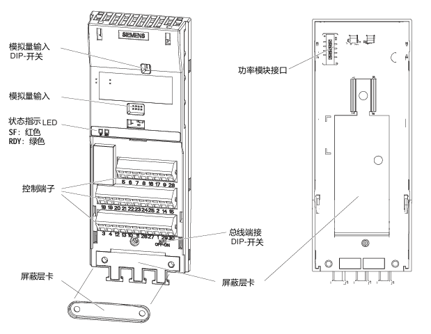
Status indicator: includes a red SF (system fault) indicator light and a green RDY (ready) indicator light.
Core interfaces: analog input interface, power module interface, control terminal, bus termination switch, shielding layer card, option interface (supporting BOP basic operation panel and other options).
(2) Definition of Core Terminals in Wiring Diagram
Terminal Number Function Description Terminal Number Function Description
1 +10V 15 PTC-
2 OV 16 DI4
3 AIO 17 DI5
4 AI0- 18 NC
5 DIO 19 NO(DO0)
6 DI1 20-23 COM, NCC, NO, COM (DO1 related)
7 DI2 24 NO(DO2)
8 DI3 25 COMJ
9 U24V 26 AO1+
10 AI1+ 27 AO1-
11 AI1- 28-29 RS485 -A、UOV
12 AO0+ 30 RS485 -B
13 AO0- - -
14 PTC+ - -
3. Technical parameters of wiring terminals
Design type: Cage spring clamping design, compatible with cable specifications of 0.2~1.5 mm ² (24~14 AWG).
I/O interface configuration: 6 digital inputs (DI), 3 digital outputs (DO), 2 analog inputs (AI), 2 analog outputs (AO), and 1 PTC interface.
Cable requirements: The maximum length of the control cable should not exceed 10 meters (32.8 feet); Unshielded cables can work, but it is recommended to use shielded cables to meet the EMC (electromagnetic compatibility) requirements of CE standards.
4. Bus connection (USS protocol)
Connection method: RS485-UPS bus connection is made through terminals 29 (RS485-A) and 30 (RS485-B).
Transmission rate: The maximum baud rate is 115200 baud.
Terminal switch: The bus terminal switch is located below terminals 29 and 30 and needs to be set according to the bus topology requirements.
5. Installation and disassembly operations
Installation: The control unit is fixed on the power module by card mounting, and the installation and operation of all G120 control units and G120 power modules are completely consistent, without distinguishing models.
Disassembly: Press the release button on the top of the power module to remove the control unit from the power module.
Pre power on inspection (14 mandatory items)
Before powering on, the following checks need to be completed one by one to ensure that the system has no safety hazards and can be started normally:
Check the serial number, check the core requirements of the project
1. The environmental conditions meet the technical requirements of the frequency converter/motor (such as temperature, humidity, dust prevention, etc.)
2. Installation firmness: The frequency converter and motor are installed firmly without looseness
3. The installation and cooling installation methods are correct, and there is sufficient cooling air supply around the equipment
4. There are no safety issues with the readiness status of the motor and application equipment, and the motor can rotate freely (without jamming or obstruction)
The grounding and protection measures of the frequency converter are good, and there are no hidden dangers of poor grounding
6. Matching of power supply voltage: The input power supply voltage meets the rated input voltage requirements of the frequency converter
7 Fuse configuration: The fuse model for the input power supply is selected correctly and installed in place
8. The motor wiring and steering motor wiring are correct, and the steering direction meets expectations when starting
9. The wiring of the motor and power supply is good, and the tightening torque should be tightened according to the technical requirements
10 motor phase sequence: The motor phase sequence is not reversed (incorrect phase sequence may cause serious damage to connected equipment)
11. Cable routing: Separate the motor power cable from other control cables to avoid interference
12. The control signal wiring is correct and meets the corresponding technical requirements
13. There are no tools or foreign objects around the environmental cleaning equipment that may cause damage to the system operation
14. Unique power supply: The frequency converter is the only power supply device for the motor (to avoid multiple power supply conflicts)
Debugging the entire process (taking STARTER software as an example)
1. Debugging core prerequisites
The frequency converter (power module+control unit) cannot be directly applied after arrival and must be debugged before being put into use.
Debugging method: ① Download a set of valid parameters through BOP or STARTER; ② Gradually complete debugging through BOP or STARTER (this guide focuses on the STARTER software debugging method, refer to the control unit operation guide for other methods).
- OMRON
- ABB
- General Electric
- EMERSON
- Honeywell
- HIMA
- ALSTOM
- Rolls-Royce
- MOTOROLA
- Rockwell
- Siemens
- Woodward
- YOKOGAWA
- FOXBORO
- KOLLMORGEN
- MOOG
- KB
- YAMAHA
- BENDER
- TEKTRONIX
- Westinghouse
- AMAT
- AB
- XYCOM
- Yaskawa
- B&R
- Schneider
- KONGSBERG
- NI
- WATLOW
- ProSoft
- SEW
- ADVANCED
- Reliance
- TRICONEX
- METSO
- MAN
- Advantest
- STUDER
- DANAHER MOTION
- Bently
- Galil
- EATON
- MOLEX
- DEIF
- B&W
- ZYGO
- Aerotech
- DANFOSS
- Beijer
- Moxa
- Rexroth
- Johnson
- WAGO
- TOSHIBA
- BMCM
- SMC
- HITACHI
- HIRSCHMANN
- Application field
- XP POWER
- CTI
- TRICON
- STOBER
- Thinklogical
- Horner Automation
- Meggitt
- Fanuc
- Baldor
- SHINKAWA
- Other Brands
- UniOP
- KUKA
- Iba
- Beckhoff
- ADLINK
-
 Applied Materials 0195-14157 CMP Tool Controller
 -
 Allen-Bradley SK-H1-PWRMOD-D590 Power Structure
 -
 Zebra RSR12-RG5G8G5G5A1A2B XSLATE R12 Rugged Tablet
 -
 LTI SC52.0040.0012.0000.0 Compact Servo Drive
 -
LTI Tools LT4400-30 Twist Socket 1/2 inch Drive
-
 Lust LTi CDE32.008 Position Controller
 -
 LUST B-DS 125.1 LTi Drives 181-00635 Module
 -
 LTI DRIVES MS100 Montageset 0927.0017
 -
 Lust LTi Servo One SO84.032.0043.0000.2 Drive
 -
 LTI CDF 30.008.C3.6 Drive Power Supply
 -
 LTI SC52.0040.0012.0000.0 Servo Drive
 -
 LTi Drive CDF30.002 Power Supply Fuse
 -
 LTI Tools LT-4621-D Deep Well Twist Socket
 -
 MOOG LTI CDE54.044.D Pitch Master Turbine Drive
 -
 LTI TOOLS LT-1460 Wheel Torque Extension Kit
 -
 LUST LTi SO82.004.0030.0000.2 Servo Drive
 -
 LTI MOTION SA54.0075.0033.0000.0 Servo Drive
 -
 LUST LTi CDE34.006 W2.0 BR Servo Drive
 -
LUST LTi MOTION CDE34.044 W2.4 H13 Servo Drive
-
LUST LTi CDE32.008 W2.2.BR Positioning Controller
-
 LUST LTi DRiVES B-DS 125.1 Braking Resistor
 -
 LTI MOTION CDE34.006.WXX.PC1 Servo Drive
 -
 LTI MOTION SO24.007.0030.1000.0 Servo Drive
 -
Lust CDD34.005.C2.1 LTI Drive
-
LTI SC52.0040.0012.0000.0 Compact Servo Drive
-
LTI Tools LT4400-30 Twist Socket 1/2 inch Drive
-
 Lust LTi CDE32.008 Position Controller
 -
 LUST B-DS 125.1 LTi Drives 181-00635 Module
 -
LTI DRIVES MS100 Montageset 0927.0017
-
 Lust LTi Servo One SO84.032.0043.0000.2 Drive
 -
LTI CDF 30.008.C3.6 Drive Power Supply
-
LTI SC52.0040.0012.0000.0 Servo Drive
-
LTi Drive CDF30.002 Power Supply Fuse
-
LTI Tools LT-4621-D Deep Well Twist Socket
-
 LTI Tools LT-1400C Wheel Torque Extension
 -
LTI SO CM-P.0122.2015.1 Servo Drive SA000-13029N
-
LTI MOTION SC32.0075.1011.0000.0 Servo Drive
-
 LTI MOTION SC34.0200.0011.0000.0-SL Servo Drive
 -
 LTI CDE34.017 W2.4 H18 Frequency Inverter
 -
 LTI SO CM-P.0122.2015.1 Servo Drive
 -
 LTI FLPF-142-3-12-560/T4 Servomotor
 -
 MOOG LTI CDE54.044.D Pitchmaster Turbine Drive
 -
Lust LTi CDB34.003.C2.4 SH Servo Controller
-
 LTI SC52.0040.0012.0000.0 Servo Drive
 -
LTI SA52.0100.0033.0000.0 Servo Driver
-
 LUST CDE 54.044.D Pitch Master Turbine Drive
 -
 Lust LTi Servo One SO84.032.0040.0000.2 Drive
 -
 LTi LSH-074-2-60-560/T1 P S4 B14.1R Servo Motor
 -
LTI SC52.0040.0012.0000.0 Servo Drive
-
 LTI CDS44.072.LC1.1.NF Servo Driver
 -
 LTI SO CM-P.0122.2015.1 Servo Drive
 -
LTI MOTION SO24.007.0030.1000.0 Servo Drive
-
LTI MOTION SC34.0300.0011.0000.0 Servo Drive
-
 LTI DRIVES GmbH MS100 Mounting Set 0927.0017
 -
 LTI CDB34.014 W2.4 BR SH Servo Driver
 -
LTi Drives 0920.0034.14 Documentation DVD
-
 LTI MOOG CDE54.044 Pitchmaster Frequency Converter 181-01019
 -
LTI LSN-097-0960-30-560 Servo Motor
-
LUST LTI CDE32.008 W2.2.BR Positioning Controller
-
LTI Drives MS100 0927.0017 Assembly Set
-
 LTI SO82.004.0030.0000.2 Servo Drive
 -
LTI MOTION SC32.0040.1011.0000.0 Servo Drive
-
LTi Drives 0920.0034.14 Product DVD
-
LTI MOOG CDE54.044 Pitchmaster Servo Drive 181-01019
-
LUST LTI CDE34.017 W2.4 Servo Drive
-
 Lust LTi Servo One SO84.032.0040.0000.2 Drive
 -
 LUST LTI SO84.012.0011.1700.2 Servo Drive
 -
LTI LSN-097-0960-30-560 Servo Motor
-
LUST CDE 54.044.D Pitch Master Turbine Drive
-
 LTI Luster SA54.0550.0033.0000.0 Servo Drive
 -
LTI CDS44.072.LC1.1.NF Servo Driver
-
 LTI DRIVES GmbH MS100 Assembly Set 0927.0017
 -
 LTi Drives DSM4-14.2-21R83-200 Servo Motor
 -
LTI Motion SC52.0150.0012.0000.0 Servo Drive
-
LTI Motion LSP04-004-048-60-0PR1PY17E0440 Servo Motor
-
 LTI KP300-R Drive Interface Operator Display
 -
 Lust LTI SO84.020.0002.0100.2 Servo Drive
 -
 LUST LTI CDD34.008.W2.1 CDD3000 Servo Drive
 -
LTI MOTION SA54.0550.0033.0000.0 Servo Drive
-
 LTI Drives MS100 0927.0017 Mounting Kit
 -
 LTi DRiVES LSP06-015-320-30-00H1MY170 Servo Motor
 -
 LTI MC6412 C1 D3 S12 Servo Drive
 -
LUST LTi SO82.004.0030.0000.2 Servo Drive
-
LTi Drives LSP06-015-320-30-00H1MY170 Servomotor
-
LUST LTi CDE34.003 C2.0 Servo Drive
-
LUST LTi LSH-127-1-30-560 T1 Servo Motor
-
 LTI MOOG CDE54.044 Pitchmaster Servo Drive
 -
LTI Lock Technology 1237 Flip Socket Set
-
LTi LSP08-028-560-55-00H1MY1M0 Servomotor
-
Lust LTi CDE34.010.D2.4 Position Controller 10A
-
 Lust LTi CDE34.010.D2.4 Positioning Controller 10A
 -
LTi Drives FLPF-142-3-12-560/T4 Servomotor
-
 LUST LTI Motion CDD54.045 W2.1 Servo Drive
 -
LUST LTI CDD34.006.W2.2.PC1 Servo Drive
-
 LTI KP200-XL Operator Panel Keypad 4 Key
 -
 Lust LTI CDE32.008 W2.2.BR Positioning Controller
 -
LTI Servo One SO82.004.0030.0000.2 Drive Amplifier
-
LTI MOTION SC54.0550.0012.0000.0 Servo Drive
-
LTI LSN-097-0510-30-560 Servo Motor
-
LTi Drives 0920.0034.14 Product DVD
-
LTI SO82.004.0030.0000.2 Servo Drive
-
MOOG LTI CDE54.044 Pitchmaster Frequency Converter
-
LUST LTI CDE34.017 W3.0 Servo Drive
-
LUST LTi Drives CDS44.072 LC1.1 Servo Drive
-
LUST LTi DC1-3.0006.1000.0 Servo Drive
-
LTi LSMM13-100-4N-001 Servo Motor
-
LTI MOOG CDE54.044 Pitchmaster Servo Drive
-
 LUST LTi Drives NFE12.3 Line Filter
 -
LTI MOTION SC34.0100.1011.0000.0 Drive
-
LUST LTi LSH-074-2-30-560/T1 B S4 G6.1M Servomotor
-
LUST LTI CDE34.044W2.3 Servo Drive
-
LUST LTi LST-127-5-15-560/T1 S4 G12.1S Servomotor
-
Lust LTi MOTION CDE34.044 W2.4 H13 Servo Drive
-
LTI Servo One SO82.004.0030.0000.2 Drive Amplifier
-
Lust LTI CDE34.006 W2.4 V4.10-02 Servo Controller
-
LTI Drives Stromag FLP 20/0014-60 BA 1 Servomotor
-
Lust LTI CDE34.024.Wx.x.PC1 Servo Controller
-
LTI Drives FLP13-0395-30-AC2 9.5 kW Servo Motor
-
LTI CDB32.004-C2.0SH Servo Drive
-
LTi LSH-074-2-30-320/T1 1R Servo Motor
-
LTi DRiVES LSP08-028-320-30-BPH2MY17E0803 Servo Motor
-
LUST LTI SO24.007.0020.0000.1 Servo Controller
-
LTI CDE34.017.W3.0 Frequency Inverter
-
LUST LTi DRIVES LSH-097-0960-30-560/T1 Servomotor
-
LTi DRiVES LSP10-056-560-50-00H1MY 1M0 Servomotor
-
LTi DRiVES LSP08-028-320-55-00H1MY 170 Servomotor
-
 LTI MC6432 C1 D3 S12 G20 Servo Drive
 -
 Keba LTi CDE32.008 C3.0 Frequency Inverter


