
SIEMENS SINAMICS G120 Control Unit CU240E
The default control and monitoring signal source for the control unit is the wiring terminal, which can be modified during debugging through parameters P0700 (command signal source) and P1000 (set value signal source).
SIEMENS SINAMICS G120 Control Unit CU240E
Detailed installation process explanation
1. Installation of core prerequisites
The control unit (CU240E) and power module need to work together and cannot operate separately; If installed incorrectly, it may cause the frequency converter to start unexpectedly, so the installation must be completed by certified personnel who have received training in the installation of such systems.
The default control and monitoring signal source for the control unit is the wiring terminal, which can be modified during debugging through parameters P0700 (command signal source) and P1000 (set value signal source).
2. Equipment structure and status indication
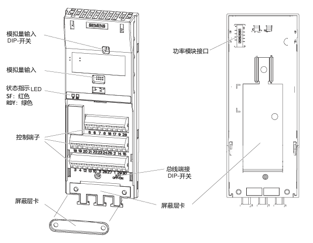
(1) Key Structure
Status indicator: includes a red SF (system fault) indicator light and a green RDY (ready) indicator light.
Core interfaces: analog input interface, power module interface, control terminal, bus termination switch, shielding layer card, option interface (supporting BOP basic operation panel and other options).
(2) Definition of Core Terminals in Wiring Diagram
Terminal Number Function Description Terminal Number Function Description
1 +10V 15 PTC-
2 OV 16 DI4
3 AIO 17 DI5
4 AI0- 18 NC
5 DIO 19 NO(DO0)
6 DI1 20-23 COM, NCC, NO, COM (DO1 related)
7 DI2 24 NO(DO2)
8 DI3 25 COMJ
9 U24V 26 AO1+
10 AI1+ 27 AO1-
11 AI1- 28-29 RS485 -A、UOV
12 AO0+ 30 RS485 -B
13 AO0- - -
14 PTC+ - -
3. Technical parameters of wiring terminals
Design type: Cage spring clamping design, compatible with cable specifications of 0.2~1.5 mm ² (24~14 AWG).
I/O interface configuration: 6 digital inputs (DI), 3 digital outputs (DO), 2 analog inputs (AI), 2 analog outputs (AO), and 1 PTC interface.
Cable requirements: The maximum length of the control cable should not exceed 10 meters (32.8 feet); Unshielded cables can work, but it is recommended to use shielded cables to meet the EMC (electromagnetic compatibility) requirements of CE standards.
4. Bus connection (USS protocol)
Connection method: RS485-UPS bus connection is made through terminals 29 (RS485-A) and 30 (RS485-B).
Transmission rate: The maximum baud rate is 115200 baud.
Terminal switch: The bus terminal switch is located below terminals 29 and 30 and needs to be set according to the bus topology requirements.
5. Installation and disassembly operations
Installation: The control unit is fixed on the power module by card mounting, and the installation and operation of all G120 control units and G120 power modules are completely consistent, without distinguishing models.
Disassembly: Press the release button on the top of the power module to remove the control unit from the power module.
Pre power on inspection (14 mandatory items)
Before powering on, the following checks need to be completed one by one to ensure that the system has no safety hazards and can be started normally:
Check the serial number, check the core requirements of the project
1. The environmental conditions meet the technical requirements of the frequency converter/motor (such as temperature, humidity, dust prevention, etc.)
2. Installation firmness: The frequency converter and motor are installed firmly without looseness
3. The installation and cooling installation methods are correct, and there is sufficient cooling air supply around the equipment
4. There are no safety issues with the readiness status of the motor and application equipment, and the motor can rotate freely (without jamming or obstruction)
The grounding and protection measures of the frequency converter are good, and there are no hidden dangers of poor grounding
6. Matching of power supply voltage: The input power supply voltage meets the rated input voltage requirements of the frequency converter
7 Fuse configuration: The fuse model for the input power supply is selected correctly and installed in place
8. The motor wiring and steering motor wiring are correct, and the steering direction meets expectations when starting
9. The wiring of the motor and power supply is good, and the tightening torque should be tightened according to the technical requirements
10 motor phase sequence: The motor phase sequence is not reversed (incorrect phase sequence may cause serious damage to connected equipment)
11. Cable routing: Separate the motor power cable from other control cables to avoid interference
12. The control signal wiring is correct and meets the corresponding technical requirements
13. There are no tools or foreign objects around the environmental cleaning equipment that may cause damage to the system operation
14. Unique power supply: The frequency converter is the only power supply device for the motor (to avoid multiple power supply conflicts)
Debugging the entire process (taking STARTER software as an example)
1. Debugging core prerequisites
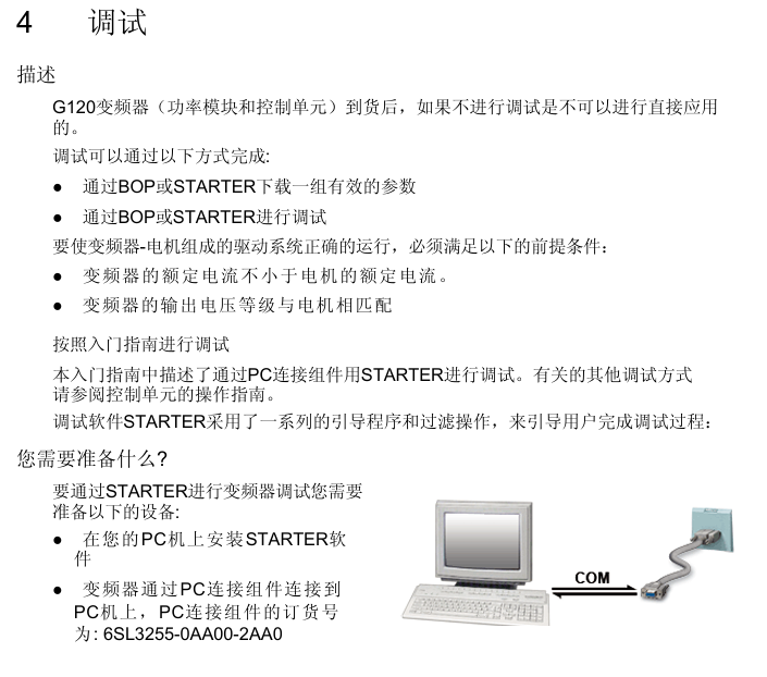
The frequency converter (power module+control unit) cannot be directly applied after arrival and must be debugged before being put into use.
Debugging method: ① Download a set of valid parameters through BOP or STARTER; ② Gradually complete debugging through BOP or STARTER (this guide focuses on the STARTER software debugging method, refer to the control unit operation guide for other methods).
Hardware matching requirements: ① The rated current of the frequency converter shall not be less than the rated current of the motor; ② The output voltage level of the frequency converter matches that of the motor.
2. Debugging preparation work
(1) Equipment and software preparation
Software: Install STARTER debugging software on the PC, which can be obtained from the supply package of PC connection components or downloaded from the latest version through the link.
Hardware: Connect the frequency converter to the PC through the PC connection component (order number: 6SL3255-0AA00-2AA0).
3. Specific debugging steps
(1) Step 1: Create a STARTER project
Power on the frequency converter, start the STARTER debugging software, select "new project", and follow the project wizard to operate.
Enter an easily recognizable project name (such as "Basic Debugging"), and click "Continue" to add comments.
Set PG/PC interface:
Click on 'Change and test...'. If the 'PC COM Port (USS)' interface already exists in the 'PG/PC interface', click on 'properties' directly; If it does not exist, click "Select..." and install "PC COM Port (USS)" in "Install/Remove Interfaces". After successful installation, click "Properties".
Configure interface parameters: Select COM ports (COM1/COM2/COM3) and baud rate (default 38400), click the "Read" button to confirm the values; If the baud rate test area displays "???", the serial port needs to be replaced; Select "Automatic mode" under the "RS485" tab and click "OK" to return.
Insert frequency converter: Name the frequency converter (such as "SINAMICS_G120_CU240E", no spaces or special characters allowed), click "Continue" to enter the summary prompt dialog box, and then click "Complete" to end the project creation.
(2) Step 2: Connect to the frequency converter online
After the project was created, STARTER was in "Offline mode" and did not establish a connection with the inverter.
Click the online connection button to pop up the online/offline data comparison dialog box: the left side shows online frequency converter data, and the right side shows offline project data.
Click on 'Load HW configuration to PG' to upload the hardware configuration of the online frequency converter to the PC. Close the dialog box to complete the online connection, and switch the software status from 'Offline mode' to 'Online mode'.
(3) Step 3: Start debugging
After successful online connection, if it is the first time debugging, a fault message F00395 will pop up (indicating that the frequency converter has not been debugged). Select the message and click "Acknowledge" to confirm and start debugging.
Double click the inverter object to enter the debugging wizard, and configure parameters according to the following process:
Control structure configuration: Confirm basic parameters such as control mode (default V/f linear characteristics), driver dataset (DDS 0), command dataset (CDS 0), etc.
Frequency converter function selection: It is recommended to choose "Identification of all parameters including the saturation curve" (automatic recognition of parameters including saturation curve). This function will perform motor data recognition once after the drive is enabled, and the motor may rotate no more than 1/4 turn. When the subsequent drive is enabled, it will optimize the rotation of the motor.
Motor data calculation: It is recommended to select "Restore factory setting and calculate motor data only", or choose "Calculate motor data only" or "Exit motor commissioning".
Summary confirmation: The debugging wizard will display the configured driver data (control structure, set values/command source default values, motor data, etc.) at the end. You can click "Copy text to clipboard" to backup, and click "Continue" to proceed to the next step.
Motor parameter recognition startup:
Click on 'Control panel', then click on 'Assume control priority' (if connected via BOP link RS232, this button will change to 'Return').
Click "Enable" to activate the ON/OFF button, and then click the ON button to start motor parameter recognition. During the recognition process, if the relevant buttons are disabled, an alarm 541 "Motor Identification Active" will be displayed.
After recognition is complete, the alarm is cancelled and the button is restored to its active state. Click on "Give up control priority!" and pay attention to the warning message that pops up.
Parameter saving: Open the SINAMICS project, click the "Copy RAM to ROM" button, and save the debugging parameters to the EEPROM of the inverter to avoid parameter loss.
(4) Step 4: Application debugging and disconnection
After basic debugging is completed, application debugging can continue through the STARTER navigation dialog box, or specific functional modules (such as input/output, setpoint channels, closed-loop control, etc.) can be fine tuned directly.
After debugging, click the disconnect button and select the save method in the pop-up save dialog box: ① Save the inverter project to the PC; ② Upload parameter settings to PC; ③ Save the parameters from RAM to EEPROM, and disconnect the PC from the inverter after completion.
4. Factory reset operation
(1) Function Description
All frequency converter parameters can be restored to their factory settings through factory reset. During the reset process, the communication memory will be reinitialized, causing communication interruption between the PC and the frequency converter.
(2) Operation steps
Ensure that the frequency converter is online (if offline, click the "connect to target system" button).
Select the frequency converter that needs to be reset in the STARTER navigation area.
Click on the factory reset icon and follow the prompts to complete the reset operation.
Fault diagnosis system
1. Definition of faults and alarms
(1) Fault
Nature: The device is in a serious abnormal state, which can affect the safe operation of the system.
Handling mechanism: When a fault occurs, the frequency converter automatically stops through the OFF2 command, and the red SF (system fault) LED on the control unit lights up; The frequency converter can only be restarted after confirming the fault.
(2) Alarm
Nature: The equipment is in an extreme state (which may cause malfunctions) or a special temporary state (such as motor parameter identification), and does not affect the basic operation of the system.
Processing mechanism: No manual response is required, the alarm status will be automatically eliminated or continuously prompted as the working conditions change.
2. Common faults and their solutions
Fault code, fault cause, handling measures
F00001 overcurrent, motor power does not match frequency converter power. Check if the rated power of the frequency converter and motor are consistent to ensure matching
F00002 overvoltage, high power supply voltage or motor in power generation state. Check if the input power supply voltage is within the rated range and investigate the cause of the motor's power generation condition
F00003 undervoltage, power failure or low voltage. Check the stability of the power supply and troubleshoot power outages or voltage drops
F00004 frequency converter overheating, exceeding the upper temperature limit, check whether the motor load is overloaded, whether the carrier pulse frequency is set reasonably, whether the ambient temperature is too high, and install a cooling fan if necessary
F00005 frequency converter overload check whether the motor power matches, whether the load change cycle is reasonable, and optimize the load working conditions
F00041 motor parameter recognition failed. Check if the wiring from the motor to the frequency converter is correct and confirm if the motor nameplate data is accurately inputted
F00052 Power module hardware data read failure. Check if the connection between the control unit (CU) and the power module (PM) is secure and in good contact
F00062 MMC data is invalid. Copy MMC parameters again to ensure a complete and uninterrupted copying process
F00070 PLC setting value fault check parameter P2040 numerical setting to ensure that the setting value is correct and effective
F00071 USS setting value fault. Use STARTER software to check if the USS communication settings (such as baud rate, address, etc.) are correct
F00072 USS setting value fault check whether the communication status and parameter configuration of the USS main station are normal
F00090 Encoder Feedback Signal Loss Check if the encoder is securely installed and wired correctly, and re debug the encoder
After replacing the F0395 CU/PM with power on, copying the startup parameters, or confirming if the device replacement process is standardized due to EEPROM read errors, perform parameter copying or debugging again, and troubleshoot EEPROM faults
3. Common alarms and their meanings
Alarm code alarm meaning
The parameters and configuration settings of A0700 PROFIBUS master station are invalid, and the PROFIBUS configuration needs to be modified
A0702 PROFIBUS connection interrupted, check the connectors, cables, and PROFIBUS master station
A0703 cannot obtain the set value from the PROFIBUS master station (control word=0) or the set value is invalid. Check the output of the master station set value
At least one intermediate node of A0704 configuration is not working or has malfunctioned
A0705 cannot obtain actual value from frequency converter (no frequency converter fault)
A0706 r2041 No diagnostic information, there may be a PROFIBUS DP software malfunction
A0710 frequency converter detected a PROFIBUS communication fault, and the communication port on the control unit may have malfunctioned
A0711 PROFIBUS parameter is invalid, check P0918 address settings and parameter P2041
4. LED status indication diagnosis
The control unit displays the device status through two LED indicator lights, with the following specific meanings:
LED name, color, status, meaning
SF (system malfunction): The red lit device indicates a system malfunction related to software and hardware
SF (system fault) red off, no system fault
SF (system fault) flashing red (0.5Hz) fault not confirmed or fault ongoing
RDY (Ready) green light indicates that the frequency converter is ready to start running (does not mean it is currently running)
RDY (Ready) green goes out. The frequency converter is not ready (such as not powered on, faults not resolved, etc.)
RDY (Ready) green flashing (0.5Hz) device in standby or transition state
- OMRON
- ABB
- General Electric
- EMERSON
- Honeywell
- HIMA
- ALSTOM
- Rolls-Royce
- MOTOROLA
- Rockwell
- Siemens
- Woodward
- YOKOGAWA
- FOXBORO
- KOLLMORGEN
- MOOG
- KB
- YAMAHA
- BENDER
- TEKTRONIX
- Westinghouse
- AMAT
- AB
- XYCOM
- Yaskawa
- B&R
- Schneider
- KONGSBERG
- NI
- WATLOW
- ProSoft
- SEW
- ADVANCED
- Reliance
- TRICONEX
- METSO
- MAN
- Advantest
- STUDER
- DANAHER MOTION
- Bently
- Galil
- EATON
- MOLEX
- DEIF
- B&W
- ZYGO
- Aerotech
- DANFOSS
- Beijer
- Moxa
- Rexroth
- Johnson
- WAGO
- TOSHIBA
- BMCM
- SMC
- HITACHI
- HIRSCHMANN
- Application field
- XP POWER
- CTI
- TRICON
- STOBER
- Thinklogical
- Horner Automation
- Meggitt
- Fanuc
- Baldor
- SHINKAWA
- Other Brands
- UniOP
- KUKA
- Iba
- Beckhoff
- ADLINK
-
 Basler Electric 9289902106 Circuit Board
 -
 Basler Electric BE1-32R Protective Relay A1E E1P BOS1P
 -
 Basler Electric RAL6144-16GM GigE Line Scan Camera with Lens
 -
 Basler Electric BE3-49R-5I5A1 Temperature Relay
 -
 Basler Electric BE1-32R Power Relay B3E E1R A0N1F
 -
 Basler Electric SR4A2B06B3A Static Voltage Regulator Features
 -
 Basler Electric 9121000106 Manual Voltage Control MVC Guide
 -
 Basler Electric SR32A-2B15B3E Static Voltage Regulator
 -
 Basler Electric SR4A2B06B3A Static Voltage Regulator Guide
 -
 Basler Electric 801A193F02 Hammond Transformer Module
 -
 Basler Electric BE1-24 Volts Per Hertz Relay A1E F1J D1S0F
 -
 Basler Electric AEC63-7 Analog Excitation Controller 220-277V
 -
Basler Electric BE132R Power Relay T245579
-
 Basler Electric MVC 108 Manual Voltage Control 90 37000 102
 -
 Basler Electric 9022900-103 Control Transformer 6-7VA 60Hz
 -
 Basler Electric BE1-79M Plug Adapter 9170111102
 -
 Basler Electric 9 2007 00 100 Current Boost System CBS 305
 -
 Basler Electric SR4A2B01B3A Static Voltage Regulator 120V
 -
Basler Electric BE1-32R Power Solid State Relay E2E A10 A0N0F
-
 Basler Electric PRS250 Veri-Sync Relay 9088800102
 -
 Basler DECS 125-15-B2C Digital Excitation Control
 -
 Basler BE 13693 002 Transformer
 -
Basler BE1-59N Ground Fault Overvoltage Relay
-
 Basler BE1-79A Reclosing Relay
 -
 Basler 9-1051-00-105 Overload Protection Module
 -
 Basler BE1-32R Power Relay – Directional Overcurrent Guide
 -
 Basler 9319700103 BE3-27T/59T-3A1N3 Voltage Relay
 -
 Basler BE1-87G Generator Differential Relay
 -
 Basler BE3-25-1D1N4 9319100106 480V Relay
 -
 Basler SR8A2B07B3A Static Voltage Regulator
 -
 Basler Electric BE4-27/59 Over/Under Voltage Relay 307-2552
 -
Basler Electric SR32A2B05B3E Static Voltage Regulator
-
Basler Electric BE1-27 A3E C3J A1N6F Solid State Protective Relay
-
 Basler Electric 9174700-100 Excitation Limiter Generator
 -
 Basler Electric BE1-87G Generator Differential Relay 09833
 -
 Basler Electric 9310200100 Power Supply Module
 -
 Basler Electric TIEE1CD0N07 Control Module
 -
Basler Electric BE1-59N Ground Fault Relay T214750
-
Basler Electric SR8A2B10B3AX Static Voltage Regulator 9060200126
-
 Basler Electric SSR 125-12 Voltage Regulator
 -
 Rolls Royce H1111.0204 Ship Main Controller
 -
 Basler Electric BE3-32-3AC Reverse Power Relay 9 1376 00 105
 -
Basler Electric BE3-25-1A1N4 Synch Check Relay 9319100100
-
 Basler Electric SR4A-2B15B3A Static Voltage Regulator
 -
 Basler Electric SR4A-2B15B3E Static Voltage Regulator
 -
 Basler Electric 9170818100 Solid State Protective Relay
 -
 Basler Electric AEC63-7 Analog Excitation Controller
 -
 Basler Electric 17483 Auxiliary Module
 -
Basler Electric BE1-59 Over Voltage Relay
-
Basler Electric 21600-101 Control Module
-
 Basler Electric KR2F Generator Voltage Regulator 9056600100
 -
 Basler BE1-CDS Current Differential System
 -
 Basler Electric CBS 212 Current Boost System 9 2650 00 100
 -
 Basler Electric IFM-150 Firing Circuit Chassis
 -
 Basler Electric BE1-60 Voltage Balance Relay C1F A1P D0C3F
 -
Basler Electric BE1-32R Power Relay A2E D1R A0N0F
-
Basler Electric BE1-32R Power Relay A2E D1R A0N0F
-
 Basler Electric 8650C80G01 Isolation Transducer PCB Board
 -
 ETEL EA-P2M-300-4/7.5A-0100-01 AccurET Modular 300 Servo Drive
 -
 Basler Electric 87T Transformer Differential Relay
 -
Basler Electric BE-6868 Power Transformer 5950007559202
-
 Basler Electric PRS250 Veri-Sync Relay 9088800102
 -
 Basler Electric SCP-250-G-60 VAR Power Factor Controller
 -
 Basler DECS-150 AVR 1NS2V1N1S Voltage Regulator
 -
Basler UFOV 260A Under Frequency Overvoltage Module
-
 Basler MOC2 199 Motor Operated Control – Overview and Setup
 -
 Basler BE3-49R-5K5A1 Temperature Relay – Complete Guide
 -
Basler BE 20035 001 Transformer – Technical Data and Installation
-
 Basler BE 02727 001 Transformer – Specifications and Usage
 -
 Basler BE127 Under Voltage Relay – Features and Application Guide
 -
Basler CBS377 Current Boost System – Complete Technical Guide
-
Basler BE1-87G P/N 9170818100 Differential Relay – In-Depth Specs
-
Basler BE1-87G Generator Differential Relay – Technical Overview
-
Basler Electric SR4A2B16 SVR Static Voltage Regulator – Complete Guide
-
 Basler Electric 9261500101 Power Supply Module
 -
 Basler Electric AEM-2020 Analog Expansion Module
 -
Basler Electric DGC-2020 Digital Genset Controller 51BRBNEAH001
-
Basler Electric BE1-59N Ground Fault Overvoltage Relay
-
Basler Electric BE1-59N-A5E-E1L-N0S1F Neutral Overvoltage Relay
-
Basler Electric MOC2499 Motor Operator Control Potentiometer 9072300430
-
 Basler Electric BE1-50/51M Overcurrent Relay
 -
 Basler Electric 9148100106 MOC3502 Solid State Relay 250VDC 0.25A
 -
 Basler Electric CBS 212 Current Boost System 9265000100
 -
Basler Electric 10493002 Control Module
-
Basler BE1-32R D3E E1R A0N1F Power Relay
-
 Basler SR8A2B15B3A Static Voltage Regulator
 -
 Basler IFM-105 Firing Circuit Chassis 9324100105
 -
Basler SR4A2B05B3A Static Voltage Regulator
-
 Basler BE151G1EB6PB0N0F Protective Relay
 -
Basler BE1-59 Electric Over Voltage Relay
-
 Basler 277 Static Programmable Powerline Carrier Channel
 -
Basler BE1-32R D1E A1P A0N1F Power Relay
-
Basler SR4A1B07B3A Static Voltage Regulator
-
 Basler Electric BE1-700 Digital Protective Relay
 -
Basler Electric SR8A-2B01B3A Static Voltage Regulator
-
Basler Electric SR4A-2B01B3E Static Voltage Regulator
-
Basler Electric 9017709102 PC Board
-
Basler Electric SR4A-2B01B3A Static Voltage Regulator
-
Basler Electric PRS-250 Veri-Sync Relay
-
 Basler Electric 9066800102 Excitation Support System
 -
Basler Electric BE1-87G Generator Differential Relay 9 1708 18 100
-
 Basler Electric 36T865-2 BE03752001 Power Supply
 -
 Basler Electric M-300 149D940G02 Power Supply
 -
 Basler Electric ACA2040-25GM 4Mp 25Fps Area Scan Camera
 -
 Basler BE1-87G-S1A-A1C-A0N0 Differential Relay
 -
Basler SR8A-2B06B3E Static Regulator SR8A2B06B3E
-
 Basler SCP-210 Frequency Controller 9095400100
 -
 Basler BE1-59-A3E-A1J-N1N3F Overvoltage Relay BE159A3EA1JN1N3F
 -
Basler 9 2011 11 100 Bracket Mounted Terminal Unit
-
Basler 9 1606 00 101 Voltage Regulator
-
 Basler CBS-377 Current Boost System 9109600102
 -
Basler 8650C72 Exciter Control Module PCB Rev 5
-
Basler C2EE1PA0N1F BE1-32R Reverse Power Relay
-
 ADLINK HPCI-14S12U - Industrial Control Backplane 12PCI Backplane PCI-14S Passive Backplane
 -
-0010.png) ADLINK PCIe-GIE74C - image acquisition card 4-CH GigE Vision PoE+ Frame Grabber
ADLINK PCIe-GIE74C - image acquisition card 4-CH GigE Vision PoE+ Frame Grabber -
-0010_1.png) ADLINK PCI-8164 - control card 4-Axis Advanced Motion Controller Board
ADLINK PCI-8164 - control card 4-Axis Advanced Motion Controller Board -
 ADLINK PCIe-U304 - 4 Port USB3 PCIe Frame Grabbers USB Screw Hole Card
 -
 ADLINK PCI-9112 - Multi-Function Data Acquisition Card DAQ Card
 -
 ADLINK PCI-7432 - 51-12013-0A50 4-CH Isolated Numérique I/O PCI Cartes Digital I/O Card
 -
 ADLINK PCA-6106P3-0C1 REV.C1 - backplane 6-Slot Passive Backplane Board
 -
 ADLINK PCI-7224 - 24-CH Opto-Isolated Digital I/O PCI Board
 -
 ADLINK CPCI-7433R(G) - Digital Input Board Rear I/O CompactPCI Card
 -
 ADLINK EBP-13E4 - 51-46703-0A30 Industrial PC Backplane Passive Backplane
 -
 ADLINK PCIE-HDV62 - Image acquisition card High Definition Video Frame Grabber
 -
 ADLINK EBP-13E4 - 51-46703-0A30 Industrial Backplane Board Passive Backplane
 -
 ADLINK 90111-B1 / CPCI-6770 - PCB CPU MODULE CompactPCI Single Board Computer
 -
 ADLINK PCI-7248 - DATA ACQUISITION PCI CARD 48-CH Parallel Digital I/O Board
 -
 ADLINK PCI-7230 - 51-12003-0a50 board PCI7230 32-CH Isolated Digital I/O Card


