YASKAWA AC Drive G7 Series (Model CIMR-G7U)
Special note: For models of 18.5kW and above, space for eyebolts and main circuit cables must be reserved. For enclosed installations of 15kW and below, top/bottom protective covers must be removed to meet heat dissipation requirements.
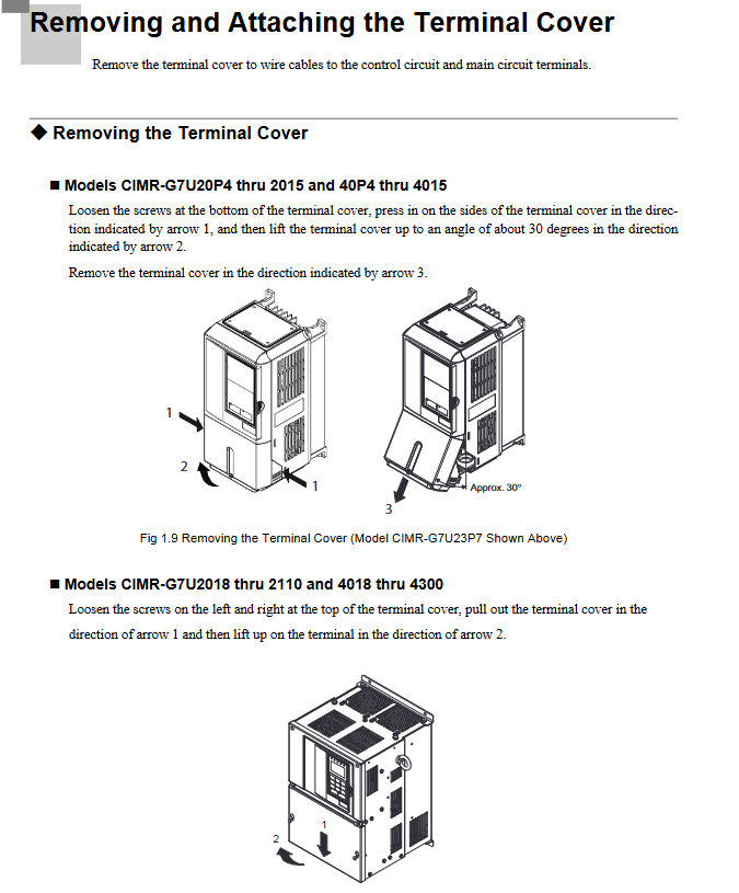
(2) Dismantling and resetting of cover plate
Terminal cover disassembly: Low power models (20P4-2015/40P4-4015): Loosen the bottom screws, press both sides and lift them up 30 ° before removing them; High power model (2018-2110/4018-4300): Loosen the top left and right screws, pull out and lift up.
Disassembly of digital manipulator: Press the side buckle of the manipulator and lift it up to remove it. When installing, the front cover should be installed first before installing the manipulator to avoid poor contact and malfunction.
2. Wiring specifications (main circuit+control circuit)
(1) Main circuit wiring
Cable specifications: Select the appropriate cable according to the model (for example, 2mm ² (14AWG) cable is recommended for the main circuit of the 200V level 0.4kW model, and 325mm ² cable is required for the 480V level 300kW model), using UL certified copper wire (75 ℃ temperature resistance).
Terminal torque: The torque of different terminal screws varies, such as M4 screws with a torque of 1.2-1.5N · m and M8 screws with a torque of 9.0-10.0N · m. Loosening can easily cause heating and fire, while tightening can easily damage the terminals.
Grounding requirements: The grounding resistance for 200V level should be ≤ 100 Ω, and for 480V level it should be ≤ 10 Ω. The grounding cable should be independent (not shared with welding machines or power tools) and the length should be as short as possible. Multiple drivers should be grounded to avoid forming loops.
(2) Control circuit wiring
Cable requirements: Use shielded twisted pair cables (recommended 0.75mm ²/18AWG), separate them from the main circuit cables (spacing ≥ 30cm), and connect the shielding layer to the driver grounding terminal (E (G)).
Terminal function: The digital input terminals (S1-S12) are 24Vdc/8mA optocoupler isolated and used for forward and reverse rotation, fault reset, etc; Analog input terminals (A1-A3) support 0- ± 10V/4-20mA signals; The capacity of relay output terminals (MA/MB/MC, etc.) is 250VAC/30VDC/1A.
Wiring inspection: After completion, it is necessary to confirm that there are no broken wires touching other terminals, no foreign objects remaining, and screws tightened. It is prohibited to use a buzzer to detect the control circuit.
Operation mode and digital manipulator
1. Core operating mode
The drive includes 5 core modes, covering requirements such as parameter settings, operation monitoring, and self-tuning:
Mode Name Core Function Operation Scenario
Drive mode monitors operational data (frequency, current, voltage), checks fault information, performs start stop operations, daily operation monitoring, and troubleshooting
Quick programming mode (Quick) sets basic parameters (control mode, frequency reference source, acceleration and deceleration time, motor rated parameters) for the first trial run, quickly configuring core parameters
Advanced Programming Mode (Adv) for viewing/modifying all parameters (PID, torque compensation, carrier frequency, etc.) in complex application scenarios (such as PID control, multi-stage operation) that require fine tuning of parameters
Verify mode only displays parameters that are different from the factory default values to confirm the modification results and avoid missing them
Before vector control, ensure that the driver matches the motor characteristics (by disconnecting the motor load) in the self-tuning mode (A. Tune) for automatic calibration of motor parameters (rotation self-tuning/static self-tuning)
2. Use of digital manipulators
(1) Key function
The core buttons include: LOCAL/REMOTE (switch local/remote control), MENU (mode selection), ESC (return to previous level), JOG (jog operation), FWD/REV (forward/reverse selection), RUN/STOP (start/stop), DATA/ENTER (confirm input).
Fault reset: When the drive reports a fault, press the Shift/RESET key to reset (the cause of the fault needs to be confirmed first).
(2) Meaning of indicator lights
FWD/REV: lit up indicates that the current command is forward/reverse; ALARM: Constant illumination indicates a fault, while flashing indicates an alarm; RUN: Constant light indicates running, flashing indicates decelerating; STOP: Constant light indicates a stop, while flashing indicates a frequency lower than the minimum output frequency.

Core content of parameter settings
1. Required basic parameters
First use requires priority configuration of the following parameters to ensure the normal operation of the device:
Parameter number, parameter name, function description, factory default value (200V level 0.4kW)
A1-02 Control mode selection: 0=V/f control, 2=open-loop vector control 1 (default), 3=flux vector control 2
B1-01 frequency reference source selection 0=digital operator, 1=control terminal (analog input) 1
B1-02 Run Command Source Selection 0=Digital Operator, 1=Control Terminal (Contact Signal) 1
C1-01 Acceleration Time 1 Acceleration time from 0 to maximum frequency (seconds) 10.0s
- ABB
- General Electric
- EMERSON
- Honeywell
- HIMA
- ALSTOM
- Rolls-Royce
- MOTOROLA
- Rockwell
- Siemens
- Woodward
- YOKOGAWA
- FOXBORO
- KOLLMORGEN
- MOOG
- KB
- YAMAHA
- BENDER
- TEKTRONIX
- Westinghouse
- AMAT
- AB
- XYCOM
- Yaskawa
- B&R
- Schneider
- Kongsberg
- NI
- WATLOW
- ProSoft
- SEW
- ADVANCED
- Reliance
- TRICONEX
- METSO
- MAN
- Advantest
- STUDER
- KONGSBERG
- DANAHER MOTION
- Bently
- Galil
- EATON
- MOLEX
- DEIF
- B&W
- ZYGO
- Aerotech
- DANFOSS
- Beijer
- Moxa
- Rexroth
- Johnson
- WAGO
- TOSHIBA
- BMCM
- SMC
- HITACHI
- HIRSCHMANN
- Application field
- XP POWER
- CTI
- TRICON
- STOBER
- Thinklogical
- Horner Automation
- Meggitt
- Fanuc
- Baldor
- SHINKAWA
- Other Brands


