
HIMA HIMatrix F2 DO 8 01 Remote I/O Module
ESD protection: Only personnel with knowledge of electrostatic protection are allowed to operate. ESD wristbands should be worn during work, and when idle, they should be stored in anti-static packaging to avoid static electricity damaging the internal circuits of the module.
HIMA HIMatrix F2 DO 8 01 Remote I/O Module
Safety regulations and environmental requirements
(1) Core security requirements
Expected use and protective measures
The module is a SELV/PELV safety ultra-low voltage device, which poses no direct danger to itself. For use in Ex areas (such as Zone 2), additional explosion-proof requirements must be met (such as installation in enclosures with protection levels above IP54);
ESD protection: Only personnel with knowledge of electrostatic protection are allowed to operate. ESD wristbands should be worn during work, and when idle, they should be stored in anti-static packaging to avoid static electricity damaging the internal circuits of the module.
Residual risk and emergency response
Residual risk sources: engineering design defects (such as wiring errors), user program vulnerabilities (such as failure to configure fault safety logic), hardware failures (such as relay adhesion), which need to be avoided through compliant configuration and regular testing;
Emergency principle: The module is an integral part of the safety system, and in the event of a malfunction, all outputs must be switched to the "power-off safety state" (such as relay disconnection). It is prohibited to perform operations that obstruct the safe operation of the system in emergency scenarios (such as forcibly activating outputs).
(2) Environment and installation conditions
Specific parameter specifications for the required type
The protection level IP20 (IEC 60529) needs to be installed inside the control cabinet to prevent dust and condensation. Ex Zone 2 requires additional enclosure protection
If the working temperature exceeds 0...+60 ° C, it needs to be downgraded to avoid oxidation of relay contacts and overheating of the circuit
Storage temperature -40...+85 ° C must be met during transportation or idle to avoid component damage
Pollution level II (IEC/EN 61131-2) is applicable to non-conductive dust environments to avoid short circuit risks
Evaluation of heat dissipation and insulation performance is required in high-altitude areas with an altitude of less than 2000 meters
Supply voltage 24 VDC (-15%...+20%) ripple factor ≤ 15%, requires independent power supply (recommended PELV/SELV power supply), equipped with 10A delay fuse
Product Description and Core Features
(1) Basic characteristics of module
Functional positioning and compatibility
Role: As a remote I/O, unable to run user programs independently, requiring SafeEthernet to receive controller instructions and expand the digital output interface of the HIMax/HIMatrix system;
Safety certification: certified by T Ü V, supporting SIL 3(IEC 61508/61511/62061)、Cat. 4(EN 954-1)、PL e(EN ISO 13849-1), Simultaneously comply with explosion-proof and industrial standards such as ATEX Zone 2 and UL 508;
Model difference: Divided into "F2 DO 8 01 (adapted to ELOP II Factory, part number 98 2200407)" and "F2 DO 8 01 SILworX (adapted to SILworX, part number 98 2200481)", the hardware is the same, only the software adaptation is different.
Core Components and Security Design
Relay output circuit: Each output is equipped with 2 forced guide contact safety relays and 1 standard relay, with a built-in 3.15A fuse (limiting switch current to 60% of rated value, in compliance with VDE 0116), and the contacts support 250 VAC/250 VDC voltage, which can be used for safe shutdown control;
Fault response mechanism: When an output fault is detected (such as relay adhesion or abnormal voltage), only the corresponding output is cut off for a single fault, and all outputs are cut off for an overall module fault. At the same time, the ERROR LED is activated and a fault code is reported;
Self testing function: supports MOT (maintenance testing) and FTT (fault tolerance time) testing, can detect safety switches, relay voltage, temperature thresholds, etc., to ensure output reliability.
(2) Hardware Structure and Interface
Core parameters
|Category | Parameter Value | Description|
|------|--------|------|
|Output channel | 8 channels | Each independent relay, normally open contact (NO), potential isolation|
|Output capacity | 250 VAC/250 VDC, maximum 3 A | Switching life under Ohmic load ≥ 3 × 10 ⁶ times|
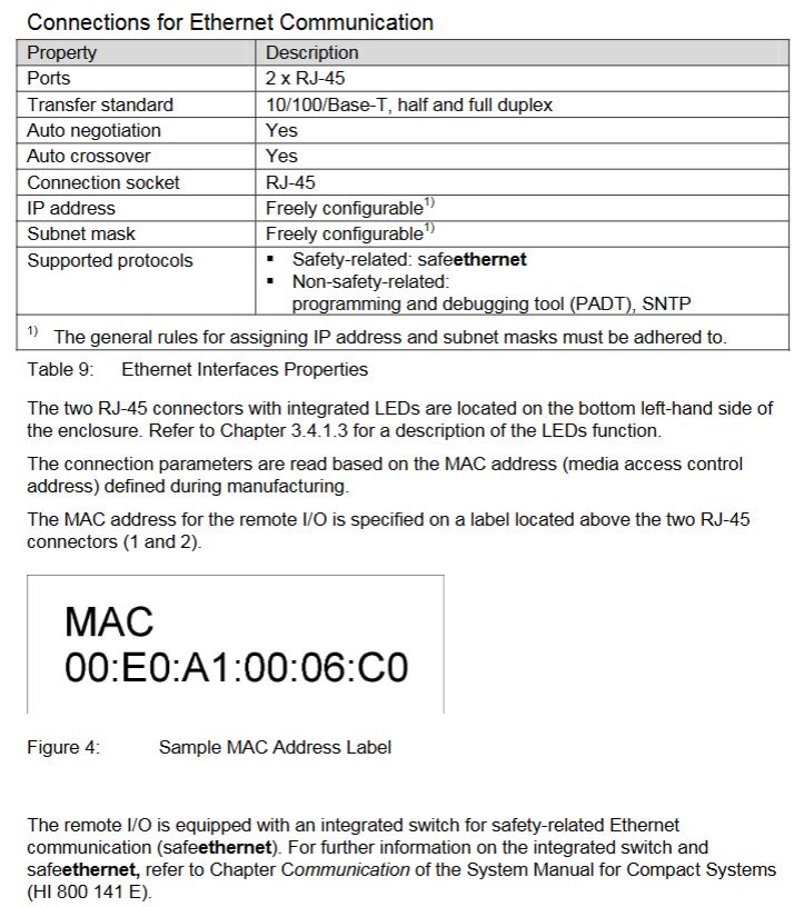
|Communication Interface | 2 × RJ-45 (SafeEthernet) | Supports 10/100 Base-T, auto negotiation rate/duplex, auto crossover (no need for crossover)|
|Supply current | Maximum 0.6 A | 24 VDC supply, power dissipation 18-46 W (depending on load)|
|Dimensions (H × W × D) | 114 × 207 × 86 mm (including fasteners) | Weight approximately 1.3 kg, supporting 35 mm DIN rail installation|
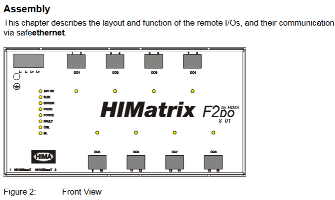
Grouping and meaning of LED indicator lights
There are 4 sets of LEDs in the front-end of the module, which perform a full light test when powered on. The status meanings of each indicator light are as follows:
Working voltage light (24 VDC, green): normally on indicates normal power supply, off indicates no voltage;
System lights (red/yellow, multiple lights):
Red light (ERROR): Constant light indicates that the module has entered the ERROR STOP state (such as hardware failure), slow flashing indicates loading the operating system;
Yellow light (Initiat/STOP/RUN): Constant light indicates corresponding status, slow flashing indicates loading configuration or forced function activation;
Communication light (green/yellow next to RJ-45): Green light constantly on indicates full duplex, flashing indicates conflict; A constant yellow light indicates a normal physical connection, while a flashing light indicates data transmission;
I/O light (DO 1-8, yellow): normally on indicates that the output is powered on (relay is engaged), and off indicates that the output is powered off (safe state).
Reset button function
Reserved reset hole in the upper left corner of the module (triggered by an insulating pin), only used for scenarios where the administrator account is forgotten or the IP address does not match: When restarting, press and hold the reset button for ≥ 20 seconds to restore the default parameters (IP: 192.168.0.99; SRS: 60000.200.0 (SILworX)/60000.0.0 (ELOP II Factory)), and clear the user account (only the default administrator account is retained, password is empty).
Installation and configuration process
(1) Module installation and wiring
Installation prerequisites
It needs to be fixed on a 35 mm DIN rail with reserved heat dissipation space around it (high power dissipation, avoid being adjacent to heating equipment);
Ex Zone 2 installation requires additional requirements: enclosure protection level ≥ IP54 (compliant with EN 60529), enclosure must be labeled with a "power off operation only" warning, equipped with a 10A delay fuse, PELV/SELV power supply, and reference to EN 60079-15 standard (terminal wiring, creepage distance, etc.).
Wiring specifications
Power wiring: Connect the positive terminal of the 24 VDC module to the "+" terminal and the negative terminal to the "-" terminal. It needs to be powered independently to avoid being in line with the power circuit;
Relay output wiring: Each output corresponds to 2 terminals (such as DO1 corresponding to terminal 1/2, A/B contacts), which are normally open contacts. The load needs to be equipped with external fuses according to the voltage type (DC loads require additional anti reverse protection);
Communication wiring: The RJ-45 interface is connected to a SafeEthernet network, supporting daisy chain topology, and requires the use of CAT 5e or higher shielded cables (shielded layer single ended grounding to reduce interference).
(2) Software configuration configuration
SILworX configuration (version ≥ 7)
Core Parameters (Module tab):
Basic parameters: Configure module name, IP address, subnet mask (default 192.168.0.99), SRS (system rack slot address, default 60000.200.0);
Fault monitoring: Enable MOT/FTT testing, configure temperature threshold (output cut-off in case of overheating), read fault codes (e.g. 0x0001 indicates module fault, 0x0400 indicates first level overheating).
Channel configuration (DO 8: Channels tab): Assign global variables to each output (DO1-DO8), set output values (1=power on, 0=power off), and monitor single channel faults (such as 0x10 indicating relay 1 feedback error).
ELOP II Factory configuration (version<7)
Assign system signals to output channels through the "Signal Editor", with configuration parameters similar to SILworX. The core difference lies in the signal mapping method (based on "signal name channel" association rather than variable allocation), and the fault code is consistent with the state definition (such as Mod. Error Code 0x0010 indicating configuration error).
Operation, maintenance, and troubleshooting
(1) Daily operation and diagnosis
operation monitoring
Real time status can be viewed through LED: the RUN light is always on to indicate normal operation, the ERROR light is on to indicate a fault, and the I/O light corresponds to the output status;
Detailed diagnosis: Read fault logs (such as relay adhesion, communication interruption) through programming tools, support online viewing of output feedback values (ensure that instructions are consistent with actual status).
Common faults and solutions
|Fault phenomenon | Possible causes | Troubleshooting steps|
|All outputs are unresponsive (all I/O lights are off) | 1 The module has not entered the RUN state; 2. Power supply failure; 3. Communication interruption | 1 Check the system light (whether it is in RUN state); 2. Measure 24 VDC power supply; 3. Check the Ethernet light (whether there is a physical connection)|
|Single output fault (ERROR light on, fault code 0x10) | 1. Relay 1 feedback error; 2. Contact adhesion | 1 Power off and restart module; 2. Check the load circuit (whether there is a short circuit); 3. Module replacement verification|
|Communication interruption (communication light off) | 1 IP address conflict; 2. Cable malfunction; 3. Controller offline | 1 Check if the module IP and PADT are on the same network segment; 2. Replace the communication cable; 3. Confirm whether the controller is operating normally|
(2) Maintenance and Lifecycle Management
regular maintenance
Operating system update: Utilize system downtime to load the latest version of the operating system through programming tools (modules must be in STOP state), and backup configuration before updating to avoid data loss;
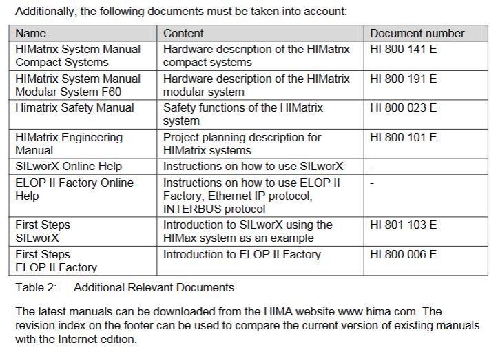
Proof Test: Conducted every 10 years, the test includes relay output on/off, fault response (such as simulating overheating), and communication link integrity. Refer to the HIMA Safety Manual (HI 800 023 E).
Scrap and transportation
Scrap: Industrial users need to dispose of modules containing electronic components in accordance with environmental protection requirements. They can contact HIMA to sign a scrap agreement, which prohibits the arbitrary disposal of modules containing electronic components;
Transportation/Storage: Original anti-static packaging should be used to avoid mechanical impact, and the storage temperature should be maintained at -40...+85 ° C to avoid humid environments.
Key terms and compliance
Core Terminology
SafeEthernet: The HIMA secure communication protocol ensures the safety of data transmission between the controller and remote I/O (compliant with SIL 3 requirements);
SRS (System. Rack. Plot): Module addressing method used to locate the position of remote I/O in the system (default 60000.200.0);
MOT (Maintenance Test): Maintenance testing to check the hardware status of safety relays, feedback loops, etc;
FTT (Fault Tolerance Time): The maximum time a module can maintain a safe state after detecting a fault.
Compliance certification
The module complies with multiple international standards, and core certifications include:
Safety standards: IEC 61508 (SIL 3), IEC 61511 (SIL 3), EN ISO 13849-1 (PL e);
Explosion proof standards: ATEX Zone 2 (EN 60079-15), UL Class I DIV 2;
Industrial standards: UL 508, NFPA 79, EN 54-2 (fire alarm).
- OMRON
- ABB
- General Electric
- EMERSON
- Honeywell
- HIMA
- ALSTOM
- Rolls-Royce
- MOTOROLA
- Rockwell
- Siemens
- Woodward
- YOKOGAWA
- FOXBORO
- KOLLMORGEN
- MOOG
- KB
- YAMAHA
- BENDER
- TEKTRONIX
- Westinghouse
- AMAT
- AB
- XYCOM
- Yaskawa
- B&R
- Schneider
- KONGSBERG
- NI
- WATLOW
- ProSoft
- SEW
- ADVANCED
- Reliance
- TRICONEX
- METSO
- MAN
- Advantest
- STUDER
- DANAHER MOTION
- Bently
- Galil
- EATON
- MOLEX
- DEIF
- B&W
- ZYGO
- Aerotech
- DANFOSS
- Beijer
- Moxa
- Rexroth
- Johnson
- WAGO
- TOSHIBA
- BMCM
- SMC
- HITACHI
- HIRSCHMANN
- Application field
- XP POWER
- CTI
- TRICON
- STOBER
- Thinklogical
- Horner Automation
- Meggitt
- Fanuc
- Baldor
- SHINKAWA
- Other Brands
- UniOP
- KUKA
- Iba
- Beckhoff
-
 Basler DECS-100-B15 Digital AVR
 -
 Basler 9284900103 PS DECS-400N
 -
 Basler D4N3H1U Intertie Protection
 -
 Basler DECS-100-B15 A15 AVR
 -
 Basler KR4F Voltage Regulator
 -
 Basler BE26434 T14 Transformer
 -
 Basler SR8A-2B15B3A Regulator
 -
 Westinghouse 774B472A12 AR Relay
 -
Basler DECS-100-B15 AVR
-
 Basler XR2002F Regulator 110V
 -
 Basler SR125-E Static Regulator
 -
 Basler SSR 125-12 Regulator
 -
 Basler MOC2599 Motor Pot
 -
 Basler BE1-DFPR Feeder Relay
 -
 Basler CBS 305 Current Boost
 -
 Basler BE1-25 AutoSync
 -
 Basler MVC 300 Voltage Control
 -
 Basler BE3-25A AutoSync
 -
 Basler KR7FF Static Regulator
 -
 Basler 90-49000-100 Regulator
 -
 Basler 880 kVA Dry Type Transformer Specs
 -
 Basler Electric BE1-25 Sync-Check Relay Specs
 -
 Basler SSR 125-12 Voltage Regulator Specs
 -
 Basler Electric BE1-851 Overcurrent Relay Review
 -
Basler Electric 149D930G02 Control Sub-Assembly
-
 Basler Electric BE1-81O/UT Frequency Relay Specs
 -
 Basler Electric BE1-51/27C Overcurrent Relay
 -
 Basler Electric 149D956G02 Industrial Component
 -
Basler Electric BE1-51A Overcurrent Relay Specs
-
 Basler Electric BE1-40Q Loss of Excitation Relay
 -
 Basler DECS-200 Excitation Control System
 -
 Basler DECS-200 Voltage Regulator 56-277V AC / 125V DC
 -
 Basler BE1-87T Transformer Differential Relay
 -
 Basler RDP-110-S1 Protection Relay
 -
 Basler BE1-700V Digital Protective Relay
 -
 Basler BE1-951 Overcurrent Protection System
 -
 Basler DECS-300 Digital Excitation Control
 -
 Basler DECS-200 Digital Excitation Control
 -
 Basler DECS-200-1C Excitation Control System
 -
Basler DECS-200-1L Digital Excitation Control
-
 Basler Electric BE1-GPS Generator Protection System
 -
Basler Electric DECS-200-1C Digital Excitation Controller
-
 Basler Electric DECS125-15 Excitation Control with Power Module
 -
 Basler Electric BE1-87G Differential Relay
 -
 Basler Electric BE1-11 Protection System I5A3M2P2N0EA00
 -
Basler Electric DECS-200-1C Excitation Control System
-
Basler Electric BE1-11g Generator Protection Relay
-
 Basler Electric DECS 125-15-B2C1 V2.0.9 Excitation Control
 -
 Basler Electric BE1-81O/UT3ED1JA7N2F Frequency Relay
 -
Basler Electric BE1-81O/UT3EE1YB7N1F Frequency Relay
-
 Basler Electric DECS-200-1L Digital Excitation Control System
 -
Basler DECS125-15-B2C1 Excitation Control
-
 Basler 9507900205 SSR Retrofit Voltage Regulator
 -
 Basler BE2000E Digital Voltage Regulator
 -
 Basler BE1-GPS Generator Protection System
 -
Basler DECS-250-CN1CN1N Digital Excitation Control
-
 Basler DGC-2020 Genset Controller
 -
 Basler BE1-81O UT3ED1LA7N0F Frequency Relay (Variant)
 -
 Basler BE1-81O UT3EE1YA9S0F Frequency Relay (Variant)
 -
Basler BE1-81O Over/Under Frequency Relay
-
Basler DECS125-15 Digital Excitation Control
-
Basler Electric BE1-951 Overcurrent Protection System
-
 Basler Electric BE1-700V Digital Protective Relay
 -
 Basler Electric APR63-5 Automatic Voltage Regulator
 -
Basler Electric BE1-851 Overcurrent Protection System
-
Basler Electric DECS-250-LN1SN1N Excitation Control
-
 Basler Electric BE1-87T Transformer Differential Relay
 -
Basler Electric DECS-200-1L Excitation Control System
-
 Basler Electric 9310300100 DECS-300 Excitation Control
 -
 Basler Electric SSE-N 125-4.5KW Shunt Exciter Regulator
 -
 Basler Electric DGC-2020HD-5NS1DNSBA Genset Controller
 -
Basler Electric BE1-81-O/UT3EE1JB7N1F Frequency Relay
-
Basler Electric BE1-81T1EE1WA0N1F Frequency Relay
-
 Basler Electric BE1-25M1EA6PN5R1F Sync-Check Relay
 -
 Basler Electric BE1-GPS Generator Protection System
 -
Basler Electric DECS-250-LN1SN1N Excitation Control Rev V
-
 Basler Electric DECS-250-CN2CN1N Excitation Control
 -
Basler Electric BE1-50/51B-207 Overcurrent Relay
-
Basler Electric DECS-300-C0N0 Excitation Control System
-
Basler Electric DECS-200 Digital Excitation Control System
-
Basler Electric DECS-250-LN1CN1N Excitation Unit
-
Basler Electric DECS-250 LN2SA1D Excitation Unit Specs
-
Basler Electric BE1-87T Transformer Relay Review
-
Basler Electric BE1-11 Protection System
-
Basler Electric BE1-GPS100-E4N1H1N Protection System
-
 Allen-Bradley 442G-MABH-R Safety Module
 -
 Beckhoff CX1030-0111 PLC Assembly Profile
 -
 FANUC IC693CPU364 PLC Module
 -
 Orange Denmark Type 200816 220 PLC Specs
 -
 OMRON C200H-SNT31 Sysmac PLC Module
 -
 Allen Bradley 20AB022A3AYNANC0 PowerFlex 70
 -
 OMRON C200HW-PCU01 Position Control Unit
 -
 ABB AO845A-eA Analog Output Module
 -
 OMRON CJ1M-CPU22 CPU Unit
 -
 Allen Bradley 100-E265ED11 Contactor
 -
 Honeywell 51304511-100 Interface Module
 -
 SOLEXY BXF3S0101N0018 Gateway Module
 -
 OMRON CJ2H-CPU65 CPU Unit
 -
 Automation Direct GS2-45P0 AC Drive
 -
 M68-2000 2-Axis Motion CNC Controller
 -
 OMRON CJ1M-CPU11 V3.0 PLC CPU Unit
 -
 OMRON CJ1W-NC413 4-Axis Positioning Controller
 -
 OMRON 3G2A3-PRO16 Programming Console HMI
 -
 Siemens 3VT8440-2AA04-2GA2 Molded Case Circuit Breaker
 -
 Siemens 3RT5045 Contactor Series
 -
 OMRON C200HS-CPU01-E SYSMAC PLC Controller
 -
 OMRON C500-NC103-E Positioning Control Unit
 -
 OMRON CJ1W-TC001 Temperature Control Unit
 -
 OMRON NJ301-1100 NJ-PA3001 PLC System EtherCAT
 -
 Pilz 773100 M1P Safety Relay Base Unit
 -
 Siemens SINUMERIK 840D SL NCU 720.3B with PLC 317-3 PN/DP
 -
 Siemens 6AV6618-7GD01-3AB0 HMI Panel
 -
 OMRON F150-C15E-3 Vision Mate Controller PLC Overview
 -
 Mitsubishi MELSEC A Series PLC System A63P A3ACPU A616AD A68RD3
 -
 M68-2000 2 Axis Motion Controller SCE SERVO CNC
 -
 OMRON FZ-S2M PLC Camera Vision System
 -
 VISOLUX SLVA-4K PLC Module from Elektronik GmbH
 -
 OMRON CJ1M-CPU23 V2.0 PLC CPU Unit
 -
 ABB AI86-16CHF PCB Card 5761751-9 B Specifications
 -
 Allen-Bradley 100-D140ZJ22L Contactor Overview
 -
 Merlin Gerin PB80 PLC Rack
 -
 WEIR WE203 Power Supply PLC
 -
 OMRON NX-TS3102 Temperature Input Unit
 -
 Siemens 6ES7146-6FF00-0AB0 I/O Module
 -
 Fanuc A16B-3300-0057 Circuit Board
 -
 OMRON CJ1W-IDP01 Input Module
 -
 Siemens 6FX2007-1AD13 Handheld Unit
 -
 Gems EM54 PLC Module PCB


