
HIMA HIMatrix F30 Compact Safety Controller
ESD protection: Only personnel with knowledge of electrostatic protection are allowed to operate. ESD wristbands should be worn during work, and when idle, they should be stored in anti-static packaging to avoid electrostatic damage to internal circuits (such as processors and relays).
|Communication interface | 4 x RJ-45 (SafeEthernet), 3 x 9-pin D-sub (FB1/FB2/FB3, supports PROFIBUS/RS485, etc.) | Supports secure and standard communication protocols|
|Clock buffer | Integrated gold capacitor, maintains clock for about 1 week after power failure | Ensure time synchronization continuity|
|Dimensions (H × W × D) | 114 × 257 × 66 mm (including fasteners) | Weight approximately 1.2 kg, supporting 35 mm DIN rail installation|
Grouping and meaning of LED indicator lights
There are a total of 5 sets of LEDs on the front end of the controller, which perform a full light test when powered on. The status meanings of each indicator light are as follows:
Working voltage light (24 VDC, green): normally on indicates normal power supply, off indicates no voltage;
System lights (red/yellow, 6 lights):
RUN (green): Constant light indicates normal operation (executing user programs), slow flashing indicates STOP status or loading of operating system;
ERROR (red): Constant light indicates entering the ERROR STOP state (such as hardware failure), slow flashing indicates operating system failure requiring reloading;
ROG (yellow): Constant light indicates loading configuration, slow flashing indicates switching to STOP state or loading operating system;
FORCE (yellow): Constant light indicates that the forced function is activated in RUN state, and slow flashing indicates that it is ready to be forced in STOP state;
FAULT (yellow): Constant light indicates configuration/operating system damage, slow flashing indicates I/O failure;
OSL/BL (yellow): Slow flashing indicates emergency loader activation/boot loader failure;
Communication light (green/yellow next to RJ-45): Green light constantly on indicates full duplex, flashing indicates conflict; A constant yellow light indicates a normal physical connection, while a flashing light indicates data transmission;
I/O light (DI 1-20/DO 1-8, yellow): normally on indicates that the channel is powered on (input valid/output engaged), off indicates that the channel is powered off (safe state);
Fieldbus light (FB1-3, yellow): The status changes with the protocol (such as always on when PROFIBUS communication is normal), please refer to the corresponding communication manual for details.
Reset button function
Reserve a reset hole in the upper left corner of the controller (triggered by an insulating pin), only for scenarios where the administrator account is forgotten or the IP address does not match: when restarting, press and hold the reset button for ≥ 20 seconds to restore the default parameters (IP: 192.168.0.99; SRS: 60000.0.0), and clear the user account (only the default administrator account is retained, password is empty). Attention: Before resetting, all fieldbus plugs must be unplugged to avoid interfering with communication with other devices.
Installation and configuration process
(1) Controller installation and wiring
Installation prerequisites
It needs to be fixed on a 35 mm DIN rail with reserved heat dissipation space around it (power loss of 12-33 W, avoiding close proximity to heating equipment);
Ex Zone 2 installation requires additional requirements: enclosure protection level ≥ IP54 (compliant with EN 60529), enclosure must be labeled with a "power off operation only" warning, equipped with a 10A delay fuse, PELV/SELV power supply, and reference to EN 60079-15 standard (terminal wiring, creepage distance, etc.).
Wiring specifications
Power wiring: Connect the positive terminal of the 24 VDC module to the "LS+" terminal, and the negative terminal to the "L -" terminal. Independent power supply is required to avoid collinearity with the power circuit;
Digital input wiring: 20 inputs are divided into 5 groups, each corresponding to independent "LS+" (sensor power supply) and "L -" (grounding), such as DI 1-4 corresponding to terminals 13 (LS+) -17 (DI4) -18 (L -), supporting passive contacts and active signals (corresponding to "L -" needs to be connected);
Digital output wiring: 8 outputs are divided into 2 groups, each corresponding to "LS+" (common terminal) and "L -" (ground). For example, DO 1-4 corresponds to terminals 1 (LS+) -5 (DO4) -6 (L -), channels 4/8 support high loads (2A @ 50 ° C), and inductive loads require parallel freewheeling diodes;
Communication wiring: RJ-45 interface connected to SafeEthernet network, supporting daisy chain topology; The D-sub interface (FB1-3) is connected to a fieldbus (such as PROFIBUS/RS485) and requires the use of shielded cables (single ended grounding of the shielding layer to reduce interference).
(2) Software configuration configuration
SILworX configuration (version ≥ 7)
Core Parameters (Module tab):
Basic parameters: Configure controller name, IP address, subnet mask (default 192.168.0.99), SRS (system rack slot address, default 60000.0.0);
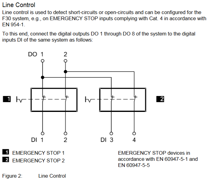
Line monitoring: Set the number of pulse channels (e.g. 1 indicates using DO1 pulse to detect the line), pulse delay (waiting time for line fault detection), and pulse slot (fixed at 3);
Fault monitoring: Enable MOT/FTT testing and read fault codes (such as 0x0010 indicating input short circuit, 0x0002 indicating output safety shutdown fault).
- OMRON
- ABB
- General Electric
- EMERSON
- Honeywell
- HIMA
- ALSTOM
- Rolls-Royce
- MOTOROLA
- Rockwell
- Siemens
- Woodward
- YOKOGAWA
- FOXBORO
- KOLLMORGEN
- MOOG
- KB
- YAMAHA
- BENDER
- TEKTRONIX
- Westinghouse
- AMAT
- AB
- XYCOM
- Yaskawa
- B&R
- Schneider
- KONGSBERG
- NI
- WATLOW
- ProSoft
- SEW
- ADVANCED
- Reliance
- TRICONEX
- METSO
- MAN
- Advantest
- STUDER
- DANAHER MOTION
- Bently
- Galil
- EATON
- MOLEX
- DEIF
- B&W
- ZYGO
- Aerotech
- DANFOSS
- Beijer
- Moxa
- Rexroth
- Johnson
- WAGO
- TOSHIBA
- BMCM
- SMC
- HITACHI
- HIRSCHMANN
- Application field
- XP POWER
- CTI
- TRICON
- STOBER
- Thinklogical
- Horner Automation
- Meggitt
- Fanuc
- Baldor
- SHINKAWA
- Other Brands
- UniOP
- KUKA
- Iba
- Beckhoff
-
 Basler D90 96801 100 PCB Card
 -
 Basler XR2002F Voltage Regulator (110 VAC, 48-480 Hz)
 -
 Basler SR8A-2B14B3A Regulator
 -
 Basler 9561500100 Module
 -
 Basler DECS-400 BE1-11 System
 -
 Basler DECS-100-B15 Excitation Control
 -
 Basler SCP 210 Frequency Controller
 -
 Basler SR4A-2B15B3A Static Voltage Regulator
 -
 Basler BE1-32R Power Relay
 -
 Basler PIA2400-17GM Power Interface Adapter
 -
 Basler MVC 232 Manual Voltage Control Module
 -
 Basler SSR 32-12 Static Voltage Regulator
 -
 Basler 5MW AVR Generator Voltage Regulator
 -
 Basler VR63-4B Voltage Regulator
 -
 Basler DECS-100-A05 AVR for Engine Generator
 -
 Basler DECS-100-B15 Automatic Voltage Regulator
 -
 Basler BE1-32R Directional Power Relay
 -
 Basler BE1-87B Differential Relay
 -
 Basler UFOV 260A Protective Module
 -
 Basler 9-2614-02-100 PCB Rev M
 -
Basler DECS-100-B15 Digital AVR
-
 Basler 9284900103 PS DECS-400N
 -
 Basler D4N3H1U Intertie Protection
 -
 Basler DECS-100-B15 A15 AVR
 -
 Basler KR4F Voltage Regulator
 -
 Basler BE26434 T14 Transformer
 -
 Basler SR8A-2B15B3A Regulator
 -
 Westinghouse 774B472A12 AR Relay
 -
Basler DECS-100-B15 AVR
-
Basler XR2002F Regulator 110V
-
Basler SR125-E Static Regulator
-
 Basler SSR 125-12 Regulator
 -
 Basler MOC2599 Motor Pot
 -
 Basler BE1-DFPR Feeder Relay
 -
 Basler CBS 305 Current Boost
 -
 Basler BE1-25 AutoSync
 -
 Basler MVC 300 Voltage Control
 -
 Basler BE3-25A AutoSync
 -
 Basler KR7FF Static Regulator
 -
 Basler 90-49000-100 Regulator
 -
 Basler 880 kVA Dry Type Transformer Specs
 -
 Basler Electric BE1-25 Sync-Check Relay Specs
 -
 Basler SSR 125-12 Voltage Regulator Specs
 -
 Basler Electric BE1-851 Overcurrent Relay Review
 -
Basler Electric 149D930G02 Control Sub-Assembly
-
 Basler Electric BE1-81O/UT Frequency Relay Specs
 -
 Basler Electric BE1-51/27C Overcurrent Relay
 -
 Basler Electric 149D956G02 Industrial Component
 -
Basler Electric BE1-51A Overcurrent Relay Specs
-
 Basler Electric BE1-40Q Loss of Excitation Relay
 -
 Basler DECS-200 Excitation Control System
 -
 Basler DECS-200 Voltage Regulator 56-277V AC / 125V DC
 -
Basler BE1-87T Transformer Differential Relay
-
 Basler RDP-110-S1 Protection Relay
 -
 Basler BE1-700V Digital Protective Relay
 -
 Basler BE1-951 Overcurrent Protection System
 -
 Basler DECS-300 Digital Excitation Control
 -
 Basler DECS-200 Digital Excitation Control
 -
 Basler DECS-200-1C Excitation Control System
 -
Basler DECS-200-1L Digital Excitation Control
-
 Basler Electric BE1-GPS Generator Protection System
 -
Basler Electric DECS-200-1C Digital Excitation Controller
-
 Basler Electric DECS125-15 Excitation Control with Power Module
 -
 Basler Electric BE1-87G Differential Relay
 -
 Basler Electric BE1-11 Protection System I5A3M2P2N0EA00
 -
Basler Electric DECS-200-1C Excitation Control System
-
Basler Electric BE1-11g Generator Protection Relay
-
Basler Electric DECS 125-15-B2C1 V2.0.9 Excitation Control
-
 Basler Electric BE1-81O/UT3ED1JA7N2F Frequency Relay
 -
Basler Electric BE1-81O/UT3EE1YB7N1F Frequency Relay
-
 Basler Electric DECS-200-1L Digital Excitation Control System
 -
Basler DECS125-15-B2C1 Excitation Control
-
 Basler 9507900205 SSR Retrofit Voltage Regulator
 -
 Basler BE2000E Digital Voltage Regulator
 -
 Basler BE1-GPS Generator Protection System
 -
Basler DECS-250-CN1CN1N Digital Excitation Control
-
 Basler DGC-2020 Genset Controller
 -
 Basler BE1-81O UT3ED1LA7N0F Frequency Relay (Variant)
 -
 Basler BE1-81O UT3EE1YA9S0F Frequency Relay (Variant)
 -
Basler BE1-81O Over/Under Frequency Relay
-
Basler DECS125-15 Digital Excitation Control
-
Basler Electric BE1-951 Overcurrent Protection System
-
 Basler Electric BE1-700V Digital Protective Relay
 -
 Basler Electric APR63-5 Automatic Voltage Regulator
 -
Basler Electric BE1-851 Overcurrent Protection System
-
Basler Electric DECS-250-LN1SN1N Excitation Control
-
 Basler Electric BE1-87T Transformer Differential Relay
 -
Basler Electric DECS-200-1L Excitation Control System
-
 Basler Electric 9310300100 DECS-300 Excitation Control
 -
 Basler Electric SSE-N 125-4.5KW Shunt Exciter Regulator
 -
 Basler Electric DGC-2020HD-5NS1DNSBA Genset Controller
 -
Basler Electric BE1-81-O/UT3EE1JB7N1F Frequency Relay
-
Basler Electric BE1-81T1EE1WA0N1F Frequency Relay
-
 Basler Electric BE1-25M1EA6PN5R1F Sync-Check Relay
 -
 Basler Electric BE1-GPS Generator Protection System
 -
Basler Electric DECS-250-LN1SN1N Excitation Control Rev V
-
 Basler Electric DECS-250-CN2CN1N Excitation Control
 -
Basler Electric BE1-50/51B-207 Overcurrent Relay
-
Basler Electric DECS-300-C0N0 Excitation Control System
-
Basler Electric DECS-200 Digital Excitation Control System
-
Basler Electric DECS-250-LN1CN1N Excitation Unit
-
Basler Electric DECS-250 LN2SA1D Excitation Unit Specs
-
Basler Electric BE1-87T Transformer Relay Review
-
Basler Electric BE1-11 Protection System
-
Basler Electric BE1-GPS100-E4N1H1N Protection System
-
 Allen-Bradley 442G-MABH-R Safety Module
 -
 Beckhoff CX1030-0111 PLC Assembly Profile
 -
 FANUC IC693CPU364 PLC Module
 -
 Orange Denmark Type 200816 220 PLC Specs
 -
 OMRON C200H-SNT31 Sysmac PLC Module
 -
 Allen Bradley 20AB022A3AYNANC0 PowerFlex 70
 -
 OMRON C200HW-PCU01 Position Control Unit
 -
 ABB AO845A-eA Analog Output Module
 -
 OMRON CJ1M-CPU22 CPU Unit
 -
 Allen Bradley 100-E265ED11 Contactor
 -
 Honeywell 51304511-100 Interface Module
 -
 SOLEXY BXF3S0101N0018 Gateway Module
 -
 OMRON CJ2H-CPU65 CPU Unit
 -
 Automation Direct GS2-45P0 AC Drive
 -
 M68-2000 2-Axis Motion CNC Controller
 -
 OMRON CJ1M-CPU11 V3.0 PLC CPU Unit
 -
 OMRON CJ1W-NC413 4-Axis Positioning Controller
 -
 OMRON 3G2A3-PRO16 Programming Console HMI
 -
 Siemens 3VT8440-2AA04-2GA2 Molded Case Circuit Breaker
 -
 Siemens 3RT5045 Contactor Series
 -
 OMRON C200HS-CPU01-E SYSMAC PLC Controller
 -
 OMRON C500-NC103-E Positioning Control Unit
 -
 OMRON CJ1W-TC001 Temperature Control Unit


