
HIMA HIMax X-SB 01 System Bus Module
ESD protection: Only personnel with knowledge of electrostatic protection are allowed to operate. ESD wristbands should be worn during work, and when idle, they should be stored in anti-static packaging to avoid damage to the module caused by static electricity.
Residual risk and emergency response
Residual risk sources: engineering design defects, user program errors, wiring faults, which need to be avoided through compliant configuration and regular testing;
HIMA HIMax X-SB 01 System Bus Module
Safety regulations and environmental requirements
(1) Core security requirements
Expected use and protective measures
The module is used to assemble safety related controller systems and must comply with SELV/PELV safety ultra-low voltage standards. Additional explosion-proof measures must be taken for use in Ex areas;
ESD protection: Only personnel with knowledge of electrostatic protection are allowed to operate. ESD wristbands should be worn during work, and when idle, they should be stored in anti-static packaging to avoid damage to the module caused by static electricity.
Residual risk and emergency response
Residual risk sources: engineering design defects, user program errors, wiring faults, which need to be avoided through compliant configuration and regular testing;
Emergency principle: The module is a component of the safety system, and in the event of a malfunction, the system must enter a safe state (such as emergency shutdown). It is prohibited to perform operations that obstruct the safe operation of the system in emergency situations.
(2) Environment and installation conditions
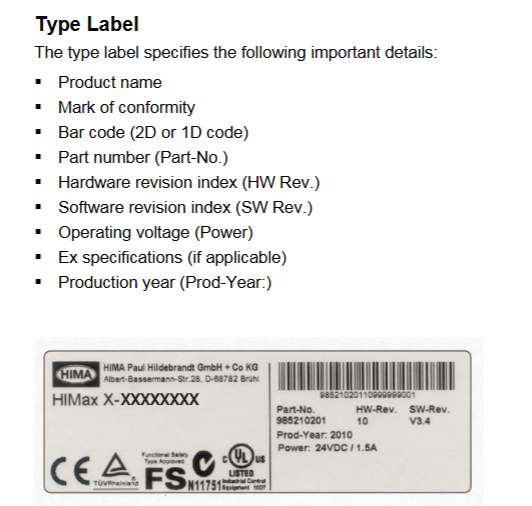
Specific parameter specifications for the required type
The protection level IP20 (IEC 60529) needs to be installed inside the control cabinet to prevent dust and condensation water
If the working temperature exceeds 0...+60 ° C, it needs to be downgraded to avoid module overheating
Storage temperature -40...+85 ° C must meet this range during transportation or idle use
Pollution level II (IEC/EN 61131-2) is applicable to non-conductive dust environments
Evaluation of heat dissipation and insulation performance is required in high-altitude areas with an altitude of less than 2000 meters
Supply voltage 24 VDC (-15%...+20%) ripple factor ≤ 5%, requires independent power supply
Product Description and Core Features
(1) Basic characteristics of module
Functional positioning and compatibility
Slot 1 and Slot 2 can only be inserted into the HIMax motherboard, supporting two operating modes:
Single module (Mono mode): Only one system bus works;
Dual module (Redundancy mode, recommended default): 2 redundant system buses to improve availability;
Safety certification: certified by T Ü V, supporting SIL 3(IEC 61508/61511/62061)、Cat. 4(EN 954-1)、PL e(EN ISO 13849-1), Data transmission adopts security related protocols.
Fault response mechanism
If a system bus fails, the redundant bus will automatically take over communication (dual modules need to be pre configured) to ensure uninterrupted data transmission; The module has built-in self detection function, which can identify hardware/software faults and power supply abnormalities. Fault information is displayed through LED indicator lights and SILworX diagnostic interface.
(2) Hardware Structure and Interface
core component
Security related processor system: 1oo2 architecture (1 out of 2), controls and monitors a single system bus (Slot 1 corresponds to bus A, Slot 2 corresponds to bus B), the operating system and fault logs are stored in non-volatile memory and can be read through SILworX;
Interface configuration:
Number of Interface Types, Functions, and Parameters
PADT service interface 1 connects to programming and debugging tools (10/100 Base-T, does not support automatic crossover, point-to-point requires crossover, IP address can be configured)
System bus interface (Up/Down) 2 connects to other baseboards (supports automatic crossover, requires CAT 5e or above Ethernet cable, RJ-45 interface)
Diagnostic interface (Diag) 1 reserved for future expansion use
Grouping and meaning of LED indicator lights
There are a total of 6 sets of LEDs on the front end of the module, and a full light test will be conducted when powered on. The status meanings of each indicator light are as follows:
Module status indicator lights (Run/Error/Stop/Init):
Run (green): Constant light indicates normal operation (RUN state), slow flashing (600ms on/600ms off) indicates STOP/OS_SOWNLOAD state;
Error (red): Constant light/slow flashing indicates detection of internal faults (such as hardware failure, power supply abnormality);
Stop (yellow): Constant light indicates STOP/valid configuration, slow flashing indicates STOP/invalid configuration;
Init (yellow): Constant light indicates Initiate initialization, slow flashing indicates LOCKED locked state.
Redundant indicator lights (Ess/Red):
Ess (yellow): Always on indicates single bus operation (removing modules can cause system failure), slow flashing indicates redundant configuration but backup modules are unavailable;
Red (yellow): Always on indicates redundant operation (bus ID synchronization successful), off indicates no redundancy.
Other indicator lights: Rack connection light (Up/Down, green/yellow indicates physical/logical connection status), Slot light (3-18, green indicates slot has module and connection is normal), Ethernet light (PADT/Up/Down/Diag, green flashing indicates data transmission, yellow indicates speed/duplex mode).
(3) Key technical parameters
Category parameter values
Maximum power supply current 0.65 A
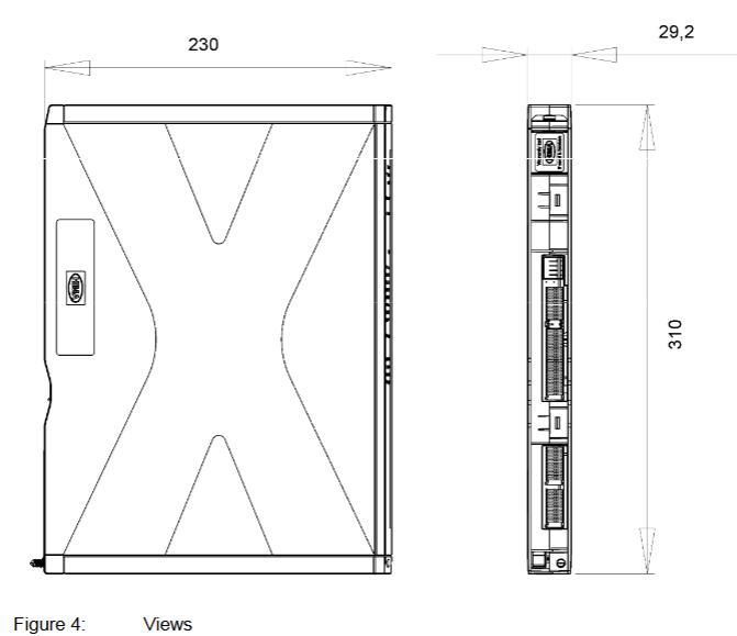
Dimensions (H × W × D) 310 × 29.2 × 230 mm
Weight approximately 1.2 kg
Maximum relative humidity of 95% (without condensation)
Installation and configuration process
(1) Module installation and removal
Installation prerequisites
It is necessary to cooperate with the dedicated connector board on the motherboard (slot 1 on the left board and slot 2 on the right board), and label the number of supported slots (10/15/18 slots) and slot IDs on the connector board;
It is necessary to install matching fan components to ensure forced heat dissipation (refer to the HIMax system manual). The time to open the fan bracket cover during operation should be less than 10 minutes to avoid heat dissipation failure.
Operation steps
Installation: Open the fan bracket cover → Insert the top of the module into the hook guide → Rotate the module downwards until it locks into place → Tighten the fixing screws → Close the cover and lock it;
Disassembly: Open the cover plate → Loosen the screws → Rotate the module upwards to detach from the guide rail → Remove the module → Close the cover plate.
(2) SILworX configuration configuration
Core Parameters (Module tab)
Network parameters: configure IP address, subnet mask, default gateway, rate mode (recommended automatic negotiation), flow control mode (recommended automatic negotiation);
Safety related parameters:
MAC Learning: Default "Conservative" (ARP cache locking for at least one aging cycle to prevent ARP spoofing), "Tolerance" mode is suitable for scenarios that require fast updates of MAC addresses;
ICMP mode: default "Echo Response" (supports ping testing, balancing security and diagnosis), "No ICMP Responses" has the highest security but cannot ping detect.
Routing Configuration (Routing tab)
Supports up to 8 routing entries, requiring configuration of destination IP address, subnet mask, and gateway for cross network communication (such as connecting to other baseboards or external devices).
Operation, Maintenance, and Lifecycle Management
(1) Daily operation and diagnosis
operation monitoring
The module does not require direct operation and can be remotely controlled through the PADT tool. The running status can be viewed in real-time through the LED (such as the Run green light indicating normal), and detailed fault information (such as IP address conflicts and bus interruptions) can be read on the SILworX diagnostic interface.
Fault handling
Common faults: IP address conflict (PADT and H/F/Col lights flashing slowly at the same time) → Reconfigure IP; Bus transient interference (Up/Down lights flashing slowly) → Check cable connection or replace CAT 5e cable;
Initialization phase fault: If the fault still reports after initialization (such as the Error light being constantly on), it is necessary to check the module power supply, configuration parameters, or replace the module.
(2) Maintenance and scrapping
regular maintenance
Operating system update: Load the latest version of the operating system during system downtime (modules need to be in STOP state, refer to SILworX online help);
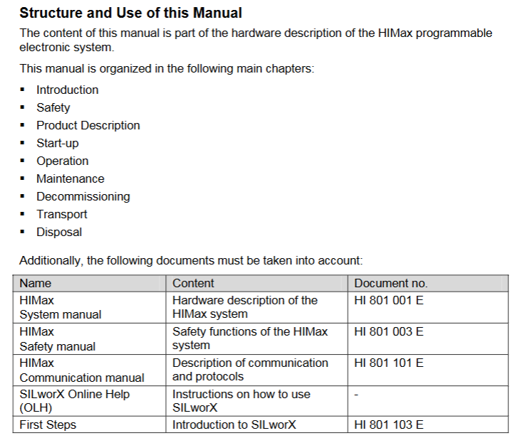
Proof Test: It needs to be performed every 10 years to ensure that the module's safety functions are functioning properly (see HIMax Safety Manual HI 801 003 E for detailed procedures).
Transportation, storage, and scrapping
Transportation/Storage: Original factory packaging (anti-static and flame-retardant) is required to avoid mechanical impact and static electricity;
Scrap: Industrial users need to dispose of modules containing electronic components in accordance with environmental protection requirements. They can contact HIMA to sign a scrap agreement, which prohibits the arbitrary disposal of modules containing electronic components.
- OMRON
- ABB
- General Electric
- EMERSON
- Honeywell
- HIMA
- ALSTOM
- Rolls-Royce
- MOTOROLA
- Rockwell
- Siemens
- Woodward
- YOKOGAWA
- FOXBORO
- KOLLMORGEN
- MOOG
- KB
- YAMAHA
- BENDER
- TEKTRONIX
- Westinghouse
- AMAT
- AB
- XYCOM
- Yaskawa
- B&R
- Schneider
- KONGSBERG
- NI
- WATLOW
- ProSoft
- SEW
- ADVANCED
- Reliance
- TRICONEX
- METSO
- MAN
- Advantest
- STUDER
- DANAHER MOTION
- Bently
- Galil
- EATON
- MOLEX
- DEIF
- B&W
- ZYGO
- Aerotech
- DANFOSS
- Beijer
- Moxa
- Rexroth
- Johnson
- WAGO
- TOSHIBA
- BMCM
- SMC
- HITACHI
- HIRSCHMANN
- Application field
- XP POWER
- CTI
- TRICON
- STOBER
- Thinklogical
- Horner Automation
- Meggitt
- Fanuc
- Baldor
- SHINKAWA
- Other Brands
- UniOP
- KUKA
- Iba
- Beckhoff
-
 Basler D90 96801 100 PCB Card
 -
 Basler XR2002F Voltage Regulator (110 VAC, 48-480 Hz)
 -
 Basler SR8A-2B14B3A Regulator
 -
 Basler 9561500100 Module
 -
 Basler DECS-400 BE1-11 System
 -
 Basler DECS-100-B15 Excitation Control
 -
 Basler SCP 210 Frequency Controller
 -
 Basler SR4A-2B15B3A Static Voltage Regulator
 -
 Basler BE1-32R Power Relay
 -
 Basler PIA2400-17GM Power Interface Adapter
 -
 Basler MVC 232 Manual Voltage Control Module
 -
 Basler SSR 32-12 Static Voltage Regulator
 -
 Basler 5MW AVR Generator Voltage Regulator
 -
 Basler VR63-4B Voltage Regulator
 -
 Basler DECS-100-A05 AVR for Engine Generator
 -
 Basler DECS-100-B15 Automatic Voltage Regulator
 -
 Basler BE1-32R Directional Power Relay
 -
 Basler BE1-87B Differential Relay
 -
 Basler UFOV 260A Protective Module
 -
 Basler 9-2614-02-100 PCB Rev M
 -
Basler DECS-100-B15 Digital AVR
-
 Basler 9284900103 PS DECS-400N
 -
 Basler D4N3H1U Intertie Protection
 -
 Basler DECS-100-B15 A15 AVR
 -
 Basler KR4F Voltage Regulator
 -
 Basler BE26434 T14 Transformer
 -
 Basler SR8A-2B15B3A Regulator
 -
 Westinghouse 774B472A12 AR Relay
 -
Basler DECS-100-B15 AVR
-
Basler XR2002F Regulator 110V
-
Basler SR125-E Static Regulator
-
 Basler SSR 125-12 Regulator
 -
 Basler MOC2599 Motor Pot
 -
 Basler BE1-DFPR Feeder Relay
 -
 Basler CBS 305 Current Boost
 -
 Basler BE1-25 AutoSync
 -
 Basler MVC 300 Voltage Control
 -
 Basler BE3-25A AutoSync
 -
 Basler KR7FF Static Regulator
 -
 Basler 90-49000-100 Regulator
 -
 Basler 880 kVA Dry Type Transformer Specs
 -
 Basler Electric BE1-25 Sync-Check Relay Specs
 -
 Basler SSR 125-12 Voltage Regulator Specs
 -
 Basler Electric BE1-851 Overcurrent Relay Review
 -
Basler Electric 149D930G02 Control Sub-Assembly
-
 Basler Electric BE1-81O/UT Frequency Relay Specs
 -
 Basler Electric BE1-51/27C Overcurrent Relay
 -
 Basler Electric 149D956G02 Industrial Component
 -
Basler Electric BE1-51A Overcurrent Relay Specs
-
 Basler Electric BE1-40Q Loss of Excitation Relay
 -
 Basler DECS-200 Excitation Control System
 -
 Basler DECS-200 Voltage Regulator 56-277V AC / 125V DC
 -
Basler BE1-87T Transformer Differential Relay
-
 Basler RDP-110-S1 Protection Relay
 -
 Basler BE1-700V Digital Protective Relay
 -
 Basler BE1-951 Overcurrent Protection System
 -
 Basler DECS-300 Digital Excitation Control
 -
 Basler DECS-200 Digital Excitation Control
 -
 Basler DECS-200-1C Excitation Control System
 -
Basler DECS-200-1L Digital Excitation Control
-
 Basler Electric BE1-GPS Generator Protection System
 -
Basler Electric DECS-200-1C Digital Excitation Controller
-
 Basler Electric DECS125-15 Excitation Control with Power Module
 -
 Basler Electric BE1-87G Differential Relay
 -
 Basler Electric BE1-11 Protection System I5A3M2P2N0EA00
 -
Basler Electric DECS-200-1C Excitation Control System
-
Basler Electric BE1-11g Generator Protection Relay
-
Basler Electric DECS 125-15-B2C1 V2.0.9 Excitation Control
-
 Basler Electric BE1-81O/UT3ED1JA7N2F Frequency Relay
 -
Basler Electric BE1-81O/UT3EE1YB7N1F Frequency Relay
-
 Basler Electric DECS-200-1L Digital Excitation Control System
 -
Basler DECS125-15-B2C1 Excitation Control
-
 Basler 9507900205 SSR Retrofit Voltage Regulator
 -
 Basler BE2000E Digital Voltage Regulator
 -
 Basler BE1-GPS Generator Protection System
 -
Basler DECS-250-CN1CN1N Digital Excitation Control
-
 Basler DGC-2020 Genset Controller
 -
 Basler BE1-81O UT3ED1LA7N0F Frequency Relay (Variant)
 -
 Basler BE1-81O UT3EE1YA9S0F Frequency Relay (Variant)
 -
Basler BE1-81O Over/Under Frequency Relay
-
Basler DECS125-15 Digital Excitation Control
-
Basler Electric BE1-951 Overcurrent Protection System
-
 Basler Electric BE1-700V Digital Protective Relay
 -
 Basler Electric APR63-5 Automatic Voltage Regulator
 -
Basler Electric BE1-851 Overcurrent Protection System
-
Basler Electric DECS-250-LN1SN1N Excitation Control
-
 Basler Electric BE1-87T Transformer Differential Relay
 -
Basler Electric DECS-200-1L Excitation Control System
-
 Basler Electric 9310300100 DECS-300 Excitation Control
 -
 Basler Electric SSE-N 125-4.5KW Shunt Exciter Regulator
 -
 Basler Electric DGC-2020HD-5NS1DNSBA Genset Controller
 -
Basler Electric BE1-81-O/UT3EE1JB7N1F Frequency Relay
-
Basler Electric BE1-81T1EE1WA0N1F Frequency Relay
-
 Basler Electric BE1-25M1EA6PN5R1F Sync-Check Relay
 -
 Basler Electric BE1-GPS Generator Protection System
 -
Basler Electric DECS-250-LN1SN1N Excitation Control Rev V
-
 Basler Electric DECS-250-CN2CN1N Excitation Control
 -
Basler Electric BE1-50/51B-207 Overcurrent Relay
-
Basler Electric DECS-300-C0N0 Excitation Control System
-
Basler Electric DECS-200 Digital Excitation Control System
-
Basler Electric DECS-250-LN1CN1N Excitation Unit
-
Basler Electric DECS-250 LN2SA1D Excitation Unit Specs
-
Basler Electric BE1-87T Transformer Relay Review
-
Basler Electric BE1-11 Protection System
-
Basler Electric BE1-GPS100-E4N1H1N Protection System
-
 Allen-Bradley 442G-MABH-R Safety Module
 -
 Beckhoff CX1030-0111 PLC Assembly Profile
 -
 FANUC IC693CPU364 PLC Module
 -
 Orange Denmark Type 200816 220 PLC Specs
 -
 OMRON C200H-SNT31 Sysmac PLC Module
 -
 Allen Bradley 20AB022A3AYNANC0 PowerFlex 70
 -
 OMRON C200HW-PCU01 Position Control Unit
 -
 ABB AO845A-eA Analog Output Module
 -
 OMRON CJ1M-CPU22 CPU Unit
 -
 Allen Bradley 100-E265ED11 Contactor
 -
 Honeywell 51304511-100 Interface Module
 -
 SOLEXY BXF3S0101N0018 Gateway Module
 -
 OMRON CJ2H-CPU65 CPU Unit
 -
 Automation Direct GS2-45P0 AC Drive
 -
 M68-2000 2-Axis Motion CNC Controller
 -
 OMRON CJ1M-CPU11 V3.0 PLC CPU Unit
 -
 OMRON CJ1W-NC413 4-Axis Positioning Controller
 -
 OMRON 3G2A3-PRO16 Programming Console HMI
 -
 Siemens 3VT8440-2AA04-2GA2 Molded Case Circuit Breaker
 -
 Siemens 3RT5045 Contactor Series
 -
 OMRON C200HS-CPU01-E SYSMAC PLC Controller
 -
 OMRON C500-NC103-E Positioning Control Unit
 -
 OMRON CJ1W-TC001 Temperature Control Unit


