
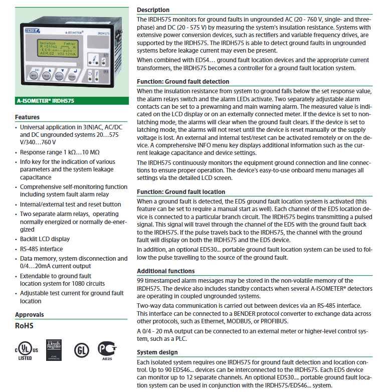
BENDER IRDH575 Series Digital Ground Fault Monitor
Applicable systems: ungrounded (floating) AC/DC systems, including 3 (N) AC, AC/DC hybrid, pure DC systems, suitable for industrial scenarios with power conversion equipment such as rectifiers and frequency converters
Core value: By monitoring the insulation resistance of the system to ground, ground faults can be detected in advance (can be identified when there is no leakage current), which can be expanded into a ground fault location system to accurately locate the fault circuit and ensure the electrical safety of ungrounded systems
BENDER IRDH575 Series Digital Ground Fault Monitor
Product Overview
(1) Product positioning and core applications
IRDH575 is an industrial grade digital grounding fault monitoring and positioning control device launched by BENDER in Germany. It is designed specifically for ungrounded (floating) AC/DC systems, with the core used to monitor the system's insulation resistance to ground, identify grounding fault risks in advance, and can be expanded into a precise grounding fault positioning system. It is suitable for complex industrial scenarios with power conversion equipment such as rectifiers and frequency converters, such as factory power distribution systems, PLC control systems, new energy equipment, etc. Through the dual functions of "fault detection+precise positioning", it ensures the electrical safety and continuous operation of ungrounded systems.
(2) Core Features and Compliance Standards
1. Core Features
Strong universality: Suitable for 3 (N) AC, AC/DC hybrid, pure DC ungrounded systems, with voltage coverage of 20-575V (low voltage type) and 340-760V (high voltage type).
Early warning: By measuring the insulation resistance (response range 1k Ω... 10M Ω), grounding faults can be detected before leakage current occurs, preventing potential problems.
Positioning Expansion: Paired with EDS4 series positioning devices, it can cover up to 1080 circuits and accurately locate fault branches and sources.
Comprehensive functions: It has multiple functions such as graded alarm, data storage, two-way communication, self-monitoring, etc., and is suitable for industrial centralized monitoring needs.
2. Compliance and Certification
Following standards: DIN EN 61557-8/9, IEC 61557-8/9, ASTM F1669M-96, IEC 60664-1 (Insulation Coordination), etc.
Environmental certification: RoHS certification, in compliance with environmental requirements.
Safety level: Flame retardant level UL94V-1, protection level IP30 (internal components)/IP40 (door mounted), suitable for harsh industrial environments.
Core functions and operational features
(1) Ground fault detection function
Insulation resistance monitoring:
Measurement principle: Inject weak test signals into the system through a built-in measurement circuit to monitor the insulation resistance of the system to ground, with a response range of 1k Ω... 10M Ω, supporting two-level independent alarm threshold settings (R_an1 warning, R_an2 main alarm), and can distinguish between "potential risks" and "serious faults" as needed.
Measurement accuracy: 10k Ω... 10M Ω range error 0%...+20%, 1k Ω... 10k Ω range error+2k Ω, measurement voltage ≤ 40V, measurement current ≤ 220 µ A (when Rf=0 Ω), will not affect the normal operation of the system.
Adaptation characteristics: Allow system leakage capacitance ≤ 150 (500) µ F, suitable for industrial systems with filtering capacitors, rated frequency range 50... 460Hz, supports low-frequency scenarios (<50Hz, reference characteristic curve).
Hierarchical alarm mechanism:
Alarm output: 3 switch contacts (SPDT), corresponding to warning (K1), main alarm (K2), system fault/EDS alarm (K3), supporting constant power on or off operation mode. Factory default K1/K2 is constant power off, K3 is constant power on.
Alarm mode: self-locking mode (manual reset after fault clearance), non self-locking mode (automatic reset after fault clearance), can be switched through menu settings.
Status indication: Alarm LED1 (warning), Alarm LED2 (main alarm), and system fault LED correspond to different alarm levels, providing visual feedback on the severity of the fault.
Self monitoring function:
Continuously monitor the grounding connection, line connection, and internal circuit status of the equipment itself. In case of abnormalities, trigger the K3 relay action and light up the system fault LED to avoid missed reporting due to equipment failure.
Support built-in/external test buttons (N/D contacts), long press the TEST button to activate self-test and verify whether the alarm circuit and display system are normal.
(2) Ground fault location function
System expansion configuration:
Core components: IRDH575 host+EDS460 (main circuit positioning)/EDS461 (control circuit positioning)+dedicated current transformers (W series/8000 series), optional EDS30... portable positioning system.
Scalability: Supports up to 90 EDS4 series devices for interconnection, with each EDS device capable of monitoring 12 circuits, covering a total of 1080 circuits, suitable for large-scale industrial power distribution systems.
Positioning workflow:
Trigger method: Automatically activate the positioning system upon detecting a ground fault, or manually activate the positioning function.
Signal transmission: IRDH575 sends pulse test signals (pulse/interval=2s/4s), with adjustable test current (≤ 1/2.5/10/25/50mA), suitable for different circuit impedance characteristics.
Fault identification: The signal is returned to the host through the fault circuit, and the LCD synchronously displays the fault EDS device address, circuit number, and signal strength (mA/µ A). The EDS device also synchronously indicates the fault channel locally.
Portable troubleshooting: optional EDS30... portable positioning system, tracks pulse signals to the source of faults, suitable for mobile troubleshooting and complex wiring scenarios.
(3) Data storage and communication functions
Data recording and querying:
Non volatile memory can store 99 alarm messages with timestamps, including fault type, insulation resistance value, occurrence time, etc. Data will not be lost after power failure, making it easy to trace and analyze faults.
The INFO key can quickly query system leakage capacitance, device setting parameters, alarm history, and other information without entering deep menus.
Communication interface:
RS-485 interface (BMS protocol): Supports bidirectional communication between devices, with a maximum cable length of 1200m. It is recommended to use shielded cable J-Y (ST) Y 2 × 0.6mm ² (shielded layer single ended PE), equipped with a 120 Ω terminal resistor (controlled by micro switch S1).
Protocol extension: Can connect to Bendel protocol converters, adapt to industrial protocols such as Ethernet, MODBUS, PROFIBUS, etc., and achieve interconnection with upper level systems such as PLC and DCS.
Analog output: 0/4... 20mA optional, load ≤ 500 Ω, can convert insulation resistance signal into standard analog quantity, and connect to external instruments or centralized monitoring system.
(4) Operation and display functions
Display system:
Backlit LCD screen (4 × 16 characters, character height 5mm), supports multilingual display such as Chinese/English, real-time display of insulation resistance value (1k Ω... 10M Ω), system status, EDS device information, alarm history, etc.
Auxiliary display: The "s" symbol indicates that a new measurement is in progress, EDS mode display (AUTO/MANUAL/ON/OFF), test pulse polarity indication (Point=valid BMS communication, H=new historical record).
Operation buttons:
Function keys: INFO (information query), MENU (menu settings), ESC (return), TEST (self-test), RESET (reset).
Navigation keys: up/down arrow keys (menu scrolling), Enter key (confirm settings).
External Expansion: Supports connecting external reset buttons (N/E contacts or jumpers), and the device can automatically reset when the terminal is open, suitable for remote operation scenarios.
Detailed technical parameters
(1) Electrical parameters
Category specific specifications
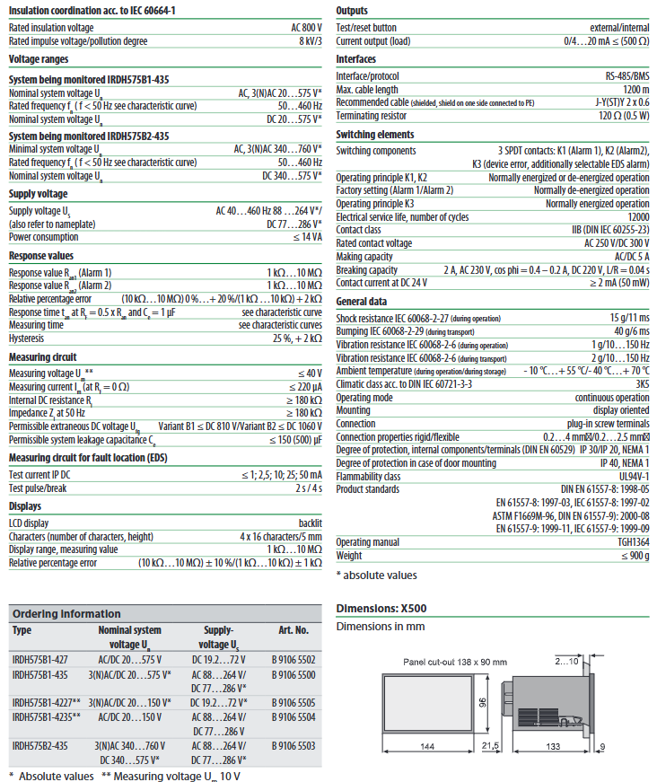
Monitoring system voltage IRDH575B1-435: AC 20... 575V (3 (N) AC/single-phase) DC 20…575V
IRDH575B2-435: AC 340... 760V (3 (N) AC/single-phase) DC 340…575V
The power supply voltage is AC 88... 264V (50... 460Hz), DC 77... 286V, and two 6A fuses are required for IT system power supply
Power consumption ≤ 14 VA
Insulation coordination rated insulation voltage AC 800V, rated impulse withstand voltage 8kV (pollution level 3)
Measure the internal DC resistance of the circuit to be ≥ 180k Ω, 50Hz impedance to be ≥ 180k Ω, and allow external DC voltage B1 ≤ 810V/B2 ≤ 1060V
Relay parameters: rated contact voltage AC 250V/DC 300V, connection capacity AC/DC 5A, breaking capacity 2 A(AC 230V,cosφ=0.4)、0.2A(DC 220V,L/R=0.04s), Electrical lifespan of 12000 cycles
Analog output 0/4... 20mA, load ≤ 500 Ω
(2) Environmental and mechanical parameters
Category specific specifications
Working environment temperature -10 ℃...+55 ℃
Storage environment temperature -40 ℃...+70 ℃
Climate grade DIN IEC 60721-3-3 (3K5)
Impact resistance performance during operation: 15g/11ms (IEC 60068-2-27); During transportation: 40g/6ms (IEC 60068-2-29)
Vibration resistance performance during operation: 1g/10... 150Hz; During transportation: 2g/10... 150Hz (IEC 60068-2-6)
Protection level: IP30 for internal components and IP20 for terminals (NEMA 1); IP40 (NEMA 1) for door installation
Installation method: Panel installation, hole size 138 × 90mm, installation direction is display facing outward
Plug in screw terminals for wiring terminals, supporting rigid conductors of 0.2... 4mm ² and flexible conductors of 0.2... 2.5mm ²
Shell and weight flame retardant grade UL94V-1, weight ≤ 900g
(3) Communication and interface parameters
Category specific specifications
Communication interface RS-485/BMS protocol, supporting bidirectional data transmission
The cable requires shielded cable J-Y (ST) Y 2 × 0.6mm ², with the shielding layer connected to PE at one end
Maximum communication distance 1200m
Terminal resistance of 120 Ω (0.5W), controlled by micro switch S1 to enable/disable
External button test button (N/D contact), reset button (N/E contact or jumper)
Backup contact STANDBY contact, when closed, the device enters standby mode and stops sending measurement signals
System installation and typical configuration
(1) Installation points
Power supply configuration: The power supply circuit is connected in series with 6A fuses, and the IT system needs to be equipped with two fuses to ensure equipment overcurrent protection.
Grounding requirements: The equipment grounding terminal (KE) should be reliably grounded, and the RS-485 cable shielding layer should be single ended with PE to reduce electromagnetic interference.
Wiring specifications: Measurement circuits and power cables should be laid separately to avoid cross interference. The wiring between EDS equipment and current transformers should follow polarity requirements.
Installation environment: Choose a location with good ventilation, away from heat sources and strong electromagnetic interference sources, and meet the requirements of working temperature (-10...+55 ℃) and protection level.
(2) Typical application configuration
1. Main circuit monitoring and positioning system (AC 20... 575V)
Configuration components: IRDH575B1-435+EDS460+W series current transformer+6A fuse.
Applicable scenarios: Factory three-phase main distribution circuit, with each EDS460 monitoring 12 main circuit branches and supporting cascading expansion of multiple EDS460 units.
Wiring method: L1/L2/L3/N passes through the current transformer, the IRDH575 host is connected to the system phase line and ground, and the EDS460 communicates with the host through the AB terminal.
2. Control circuit monitoring and positioning system (DC 20... 308V)
Configuration components: IRDH575B1-435+EDS461+8000 series current transformer+PLC.
Applicable scenarios: PLC control circuits, DC instrument circuits, EDS461 adapts to the high sensitivity requirements of control circuits and supports monitoring of grounding faults in PLC input and output circuits.
Wiring method: The control circuit wire passes through the current transformer, and IRDH575 and EDS461 communicate through the AB terminal. The analog output is connected to the PLC for centralized monitoring.
Model specifications and ordering information
(1) Core model differentiation
Model Monitoring System Voltage Range Applicable Scenarios Key Characteristics
IRDH575B1-435 AC 20... 575V, DC 20... 575V low voltage ungrounded system (industrial+civilian) basic type, covering the vast majority of industrial control and distribution systems
IRDH575B2-435 AC 340... 760V, DC 340... 575V high voltage ungrounded system (industrial specific) adapted to high voltage distribution circuits, allowing for higher external DC voltages
(2) Recommended supporting components
Component Name, Model, Function Description, Applicable Scenarios
The main circuit positioning device EDS460 monitors 12 AC main circuit branch factory main distribution and motor circuits
Control circuit positioning device EDS461 monitors 12 DC control circuit branches PLC control and instrument circuits
Portable positioning system EDS3090/EDS3091 mobile tracking fault source complex wiring, hidden fault troubleshooting
The W series current transformer is compatible with the AC main circuit and is compatible with EDS460
The 8000 series current transformer is compatible with DC control circuits and is compatible with EDS461
Protocol Converter - Convert to MODBUS/PROFIBUS for centralized monitoring of the upper system
Precautions and Maintenance Guidelines
(1) Precautions for use
Equipment installation and wiring must be operated by qualified electrical professionals, strictly following local electrical safety regulations and manual requirements.
It is strictly prohibited to modify the internal circuits or parameters of the equipment without authorization. The test current setting should match the circuit characteristics to avoid damage to the load caused by excessive current.
When wiring, it is necessary to distinguish between the monitoring system voltage and the power supply voltage to avoid permanent damage to the equipment caused by misconnection. The IT system power supply must be equipped with two fuses.
RS-485 communication cables require the use of shielded cables, with the shielding layer grounded at one end. Terminal resistors should be used for long-distance communication to reduce signal attenuation and interference.
(2) Key points of daily maintenance
Regular inspection: Check the status of the LED indicator lights, whether the wiring terminals are loose, and whether the grounding connection is reliable every month to ensure the normal operation of the equipment.
Functional testing: Long press the TEST button every quarter for self inspection to verify whether the alarm output and display system are normal, and at the same time check the response of alarm linkage devices (such as sound and light alarms, circuit breakers).
Data cleaning: After reaching 99 alarm history records, they need to be cleaned up in a timely manner to avoid affecting the storage of new data. They can be cleared through the RESET button or menu operation.
Fault handling: If an alarm occurs, first check the insulation resistance value and fault location through the LCD, and troubleshoot issues such as insulation damage and load leakage. After troubleshooting, press the RESET button to reset.
- OMRON
- ABB
- General Electric
- EMERSON
- Honeywell
- HIMA
- ALSTOM
- Rolls-Royce
- MOTOROLA
- Rockwell
- Siemens
- Woodward
- YOKOGAWA
- FOXBORO
- KOLLMORGEN
- MOOG
- KB
- YAMAHA
- BENDER
- TEKTRONIX
- Westinghouse
- AMAT
- AB
- XYCOM
- Yaskawa
- B&R
- Schneider
- KONGSBERG
- NI
- WATLOW
- ProSoft
- SEW
- ADVANCED
- Reliance
- TRICONEX
- METSO
- MAN
- Advantest
- STUDER
- DANAHER MOTION
- Bently
- Galil
- EATON
- MOLEX
- DEIF
- B&W
- ZYGO
- Aerotech
- DANFOSS
- Beijer
- Moxa
- Rexroth
- Johnson
- WAGO
- TOSHIBA
- BMCM
- SMC
- HITACHI
- HIRSCHMANN
- Application field
- XP POWER
- CTI
- TRICON
- STOBER
- Thinklogical
- Horner Automation
- Meggitt
- Fanuc
- Baldor
- SHINKAWA
- Other Brands
- UniOP
- KUKA
- Iba
- Beckhoff
-
 OMRON C60H C6DR DE V1 Sysmac PLC
 -
 MITSUBISHI ELECTRIC A2ACPU21 S1 CPU Module
 -
 ABB BAILEY INNPM12 Network Process Module
 -
 HONEYWELL 620 0073C IPC PLC Module
 -
 Mitsubishi 15050 PR02B PLC Circuit Board
 -
 SIEMENS 6SY7000 0AC37 Drive Control Module
 -
 OMRON TJ2 ECT16 Traxial EtherCAT Controller
 -
 GE Fanuc IC698PSD300D Power Supply Module
 -
 Texas Instruments Series 505 16 Position Base
 -
 OMRON YASKAWA SGDH 10DE OY Servo Drive
 -
 Allen‑Bradley 440G-MT Safety Interlock Switch Specs
 -
 Rubycon PD27A 24V 8A Power Supply Module
 -
 SK-H1-GDB1-F11D PLC Gate Driver Board Kit
 -
 VIPA 441-4UA14 451-4UA14 PLC Module Rack
 -
 Mitsubishi FX5U-80MT ESS PLC Controller Specs
 -
 Mitsubishi Q64TCRTN Temperature PLC Module
 -
 GE 1C31170G Rev10 PLC Circuit Board Module
 -
 Schneider TWDLMDA40DTK PLC Controller Module
 -
 Omron FQM1-MMA22 Motion Control Module Specs
 -
 OMRON CJ1W-NCF71 Position Control Unit Specs
 -
 Schneider TSXETY4103 Ethernet Module
 -
 Mitsubishi Q12PHCPU Process CPU
 -
 Yaskawa 3G3HV-A4022-CE AC Drive
 -
 Cincinnati Milacron 3-533-0669G Temperature Control Board
 -
 Allen Bradley 20AC030A3AYNANC0 PowerFlex 70 Drive
 -
 Siemens 6ES7314-6BG03-0AB0 CPU 314C-2 DP
 -
 Carrier 17EX54007903 PLC Module
 -
 OMRON CS1W-V600C12 ID Controller Module
 -
 Honeywell 51402755-100 PCB Card
 -
 Heidenhain ECN 113 Rotary Encoder
 -
 OMRON B7AM-8B16 I/O Terminal Block
 -
 Fanuc A06B-6110-H026 Power Supply Module
 -
 Schneider TSXETG3021 Ethernet Gateway
 -
 OMRON CS1W-CLK21-V1 Controller Link Unit
 -
 NP1W6406T-Z704 PLC I/O Module
 -
 OMRON CJ1W-DA08C Analog Output Module
 -
 Yaskawa 3G3HV-A4022-CE AC Drive
 -
 OMRON NB7W-TW01B CP1L-EL20DR-D Power Panel
 -
 OMRON C500-NC103-E Position Control Unit
 -
 Steag Hamatech PLC DCS Servo Control System
 -
 Siemens 6SN1123-1AA00-0DA1 Power Supply Module
 -
 GE IC693CHS391H CPU & AD693CMM301A PLC Module
 -
 Siemens 6FC5303-0AF23-1AA1 PLC Control Panel
 -
 Square D CM4000T PowerLogic Circuit Monitor J1 F16
 -
 Siemens 6FX5002-5DG10-1BA0 MOTION-CONNECT 500 Cable
 -
 Schmersal SRB324ST 101195504 Safety Relay 24V
 -
 Mitsubishi 15050-PR02A PLC Circuit Board Module
 -
 OMRON CQM1-AD041 Analog Input PLC Module
 -
 Beckhoff EL5042 EtherCAT PLC Terminal Module
 -
 OMRON C200HW-MC402-E Motion Control Unit
 -
 C36TC0UA1100 Industrial Temperature Controller
 -
 NL8048BC24 12 Industrial Control LCD Module
 -
 OMRON R88D Servo Drive and Motor System
 -
 OMRON CS1W CLK21 V1 Controller Link Module
 -
 OMRON YASKAWA R7M A20030 S1 D Servo Motor
 -
 SIEMENS 6AV2128 3KB06 0AX1 Unified Comfort Panel
 -
 Schneider Electric METSEPM8240 PowerLogic Meter
 -
 Advanced AMCI 1PLC 1 31F Programmable Limit Switch
 -
 ABB PM582 ETH Programmable Logic Processor
 -
 SIEMENS 6FC5110 0CB01 0AA0 CPU Control Board
 -
 Schleicher P03GS13A CPU Module
 -
 Siemens 6SN1123-1AA00-0BA1 Power Module
 -
 Mitsubishi A1S61PN Power Supply Module
 -
 Yaskawa CPS-IONB DC Power Supply Module
 -
 Siemens 6ES7215-2BD00 CPU 215-2
 -
 Mitsubishi A2ACPU MELSEC PLC System Kit
 -
 ProSoft 3150-MCM Communication Module
 -
 Mitsubishi OSE104ET Incremental Encoder
 -
 OMRON CJ1W-AD081-V1 Analog Input Module
 -
 Broadcom BCM5464A1KRB Quad Port Ethernet IC
 -
 Modicon M221-24IO TM221C24 PLC 24 PNP Transistor
 -
 Allen-Bradley 1321-3R160-B Line Reactor 3R160B
 -
 Beckhoff CX1020-0012 Embedded PLC Module Specs
 -
 Turck BL20-PF-24VDC-D Power Feed Module Specs
 -
 Siemens 6SY7000-0AC37 Power Supply Module
 -
 Yaskawa SGDH-10DE-OY 1kW 400V Servo Drive Specs
 -
 Omron 3G3SV-BB015-E 1.5kW 220V VFD Specs
 -
 Uni-Pro CPU91-PLC J 23.020167X Processor Module
 -
 PASABAN MTC-3044 PLC Rack Power Supply 4835-A
 -
 XYCOM 3015T Operator Interface Panel BIN4.4.4
 -
 OMRON CJ1W-MD261 Mixed I/O Module
 -
 Omron NJ301-1100 PLC CPU eCat EIP Specs
 -
 Omron F500-C15-ETN Vision System PLC Module
 -
 Modicon M241-24IO TM/T2UK PLC with Ethernet
 -
 SIXNET YS-800-001 RTU PLC Module
 -
 BEMAC UST-202-D Interface Board 1307D V08B2
 -
 Yaskawa JANCD-MMOIC-02 Drive Circuit Board
 -
 ABB 3BSE005028R1 SDCS-COM-1 Comm Board
 -
 Omron 3G3MX2-A4110 A4150 Inverter Drives Specs
 -
 KEYENCE CA-E100 PLC Module
 -
 GE IC693ALG223-GB Analog Input Module Specs
 -
 ABB BAILEY IMMFP01 Multi Function Processor System
 -
 SIEMENS 6FC5372 0AA00 0AA1 NCU 7202 Controller
 -
Modicon TM241CE4 40I O Transistor Programmable Controller
-
 SIEMENS 6ES7 315 2EH13 0AB0 CPU 3152 PN DP
 -
 NORIS A1 91 PCB Card Rack Module System
 -
 SIEMENS 6ES7 313 5BE01 0AB0 Compact CPU
 -
 SCHNEIDER ELECTRIC S144B MICROLOGIC 60A Trip Unit
 -
 CNI PLC269 v3 Control Module Board Rev H
 -
ABB BAILEY IIMCP02 Processor Module
-
 OMRON NT20S ST121 EV3 Operator Interface Terminal
 -
 OMRON NS-CA001 Video Input Unit
 -
 GE Fanuc IC695CHS012 RX3i Backplane
 -
 Allen Bradley 2711E-K14C6 PanelView 1400e Terminal
 -
 Siemens Sinamics CCB 10000432.71 Power Cell
 -
 Siemens 6SL3210-1SE21-8UA0 Power Module PM340
 -
 Yaskawa CIMR-F7A20P4 AC Drive
 -
 Beckhoff EP1918-0002 EtherCAT Box I/O Module
 -
 OMRON CQM1-TC001 Temperature Control Module
 -
 GE Fanuc SGHA36AT0400 Industrial Contactor
 -
 OMRON NJ501-1500 PLC Machine Automation Controller
 -
 Mitsubishi MAZAK QX084 Power Supply MELDAS 500 CNC
 -
 B&R 0AC808.9 PLC Automation Module
 -
 OMRON CP1H-XA40DT1-D PLC Module
 -
 G&W Electric PLC15 5111 011 15kV Capnut Assembly
 -
 GE DS200SLCCG3AGH PCB Circuit Board
 -
 Siemens SINUMERIK 6FC3981-4FD PLC Extension
 -
 OMRON F300-DC I/O Image Processing Unit
 -
 FANUC A06B-0314-B002 AC Servo Motor
 -
 GC-S84 Programmable Controller Logic Module
 -
 PASABAN MONTELEC MTC3001-DC Drive Control PLC
 -
 Allen Bradley 100E460EJ11 Auxiliary Contactor
 -
 Bosch Rexroth 1070075337-101 Card Parameters
 -
 HMS Anybus AB7646-F Gateway Specifications
 -
 Bosch 062633-303401 CNC Servo PLC Card
 -
 TI 500-5023 Series PLC Power Supply
 -
 Siemens C98043-A7002-L1-12 Circuit Board
 -
 Omron E5CC-RX3A5M-000 Controller


