How to install and operate KBAC series adjustable frequency drive?
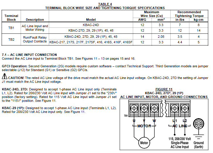
Other connections: including remote main speed potentiometer, remote start stop switch, automatic restart (requiring cancellation of start stop switch and hard wiring), voltage following (0-5V DC analog signal that needs to be isolated), enable circuit, operation/fault relay, etc., all have specific wiring methods and precautions.
(4) Bus capacitor repair
If the drive is stored for more than one year, it is necessary to apply AC input voltage in shutdown mode for at least 1 hour to repair the power bus capacitor, otherwise the capacitor may be damaged.
Operation and Debugging
(1) Start the program
After completing the jumper and fine adjustment potentiometer settings and wiring, connect the AC power supply, and the power (PWR) LED green light will turn on. Use the start stop switch to briefly place it in the "start" position to start the driver, and the motor will accelerate to the set speed. If the motor turns in the wrong direction, replace any two motor leads after powering off.
(2) Restart after malfunction
Drive monitoring includes five types of faults: undervoltage, overvoltage, motor short circuit, overload, and phase loss. After the faults are cleared, restart through the start stop switch; If the start stop switch is cancelled, the AC power supply needs to be disconnected and reconnected to restart. Partial faults (such as overvoltage) can be automatically restarted after the voltage returns to normal in automatic power-off recovery mode.
(3) Fine tuning potentiometer adjustment
Minimum speed (MIN): Factory set to 0% of the frequency setting, clockwise rotation can increase the minimum speed.
Maximum speed (MAX): Factory set to 100% of the frequency setting, counterclockwise/clockwise rotation can reduce/increase the maximum speed.
Acceleration (ACCEL): The factory setting is 1.5 seconds. Clockwise/counterclockwise rotation extends/shortens the acceleration time, and rapid acceleration may trigger the current limiting circuit to extend the acceleration time.
Decel: The factory setting is 1.5 seconds, and clockwise/counterclockwise rotation extends/shortens the deceleration time. In high inertia load applications, the deceleration time may be automatically extended. It is recommended to set the acceleration and deceleration time to 10 seconds or more for high inertia loads.
DECEL (Direct Current Injection Braking): Only when J7 is set to "INJ", this potentiometer is used to set the time for direct current to be applied to the motor. It is factory set to regenerative braking (J7 is set to "RG").
Slip Compensation (COMP): Factory set to 1.5 volts per hertz, clockwise/counterclockwise rotation increases/decreases slip compensation, and can be adjusted through specific steps to achieve speed stability under different loads.
Motor overload (I2t) and RMS current limit (CL): The factory setting is 160% of the rated current of the driver. Clockwise/counterclockwise rotation increases/decreases the current limit, which needs to be adjusted step by step and cannot exceed the rated current of the motor by 160% to avoid motor overheating.
Boost (BOOST): The factory setting is a fixed boost (J6 is set to "FIX"), which can be adjusted when J6 is set to "ADJ". It operates in the frequency range of 0-15Hz and needs to be adjusted step by step to avoid overheating and damage to the motor winding caused by excessive boost.
Jog: An optional run stop jog switch kit is required, which can set the jog speed. When the switch is in the "jog" position, the speed is set by the fine adjustment potentiometer, and when in the "run" position, the speed is set by the main speed potentiometer.
Diagnosis and fault handling
(1) Diagnostic LED
Power LED (PWR): When the AC power is turned on, the green light will turn on. It should not be used as a basis for power outage. Before maintenance, make sure that the main power switch or circuit breaker is disconnected.
Status LED (ST): It is a three color LED with different flashing frequencies and colors corresponding to different operating states and faults, such as normal operation (green light flashing slowly), overload (red light constantly on when 120% -160% full load; red light flashing rapidly when timeout trips), short circuit (red light flashing slowly), undervoltage (red and yellow light flashing rapidly), overvoltage (red and yellow light flashing slowly), stop (yellow light constantly on), standby (yellow light flashing slowly, only when installing forward and reverse switches), input phase loss (yellow light flashing rapidly, specific models), overheating trip (red and yellow light flashing rapidly, specific models), and the status will change accordingly after troubleshooting.
(2) Common fault handling
Overload fault: After clearing the fault, restart and check the motor current with an AC RMS ammeter. If the current limit is set too low, adjust it.
Overvoltage fault: In automatic power-off recovery mode, the driver automatically restarts after the voltage returns to normal.
Motor steering error: replace any two motor leads after powering off.
Other faults: troubleshoot according to the status LED indication, such as checking the motor wiring for short circuits, checking the input voltage for undervoltage/overvoltage, checking the input circuit for phase loss (specific model), and checking the heat dissipation for overheating (specific model).
- ABB
- General Electric
- EMERSON
- Honeywell
- HIMA
- ALSTOM
- Rolls-Royce
- MOTOROLA
- Rockwell
- Siemens
- Woodward
- YOKOGAWA
- FOXBORO
- KOLLMORGEN
- MOOG
- KB
- YAMAHA
- BENDER
- TEKTRONIX
- Westinghouse
- AMAT
- AB
- XYCOM
- Yaskawa
- B&R
- Schneider
- Kongsberg
- NI
- WATLOW
- ProSoft
- SEW
- ADVANCED
- Reliance
- TRICONEX
- METSO
- MAN
- Advantest
- STUDER
- KONGSBERG
- DANAHER MOTION
- Bently
- Galil
- EATON
- MOLEX
- DEIF
- B&W
- ZYGO
- Aerotech
- DANFOSS
- Beijer
- Moxa
- Rexroth
- Johnson
- WAGO
- TOSHIBA
- BMCM
- SMC
- HITACHI
- HIRSCHMANN
- Application field
- XP POWER
- CTI
- TRICON
- STOBER
- Thinklogical
- Horner Automation
- Meggitt
- Fanuc
- Baldor
- SHINKAWA


