
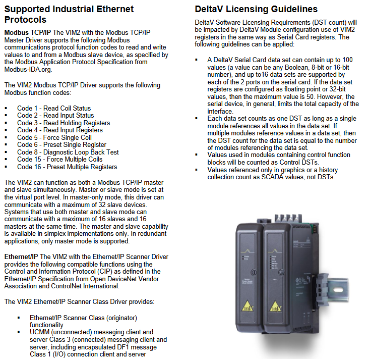
Emerson DeltaV M Series Virtual I/O Module 2 (VIM2)
Modular and flexible installation: Adopting the same installation method as the DeltaV controller, it can be installed in the controller slot of a 2-wide horizontal carrier or a 4-wide vertical carrier (located on the left side of the DeltaV controller), using standard DeltaV power supply. The design is durable and can operate stably for a long time.
Details of Function Implementation
(1) Implementation of I/O simulation function
Hardware coordination: The VIM2 hardware preloads the I/O simulation driver and communicates with the MiMiC software through the simulation network. After disconnecting the real I/O card from the control system, the MiMiC driver directly writes simulation signals to the I/O subsystem of the DeltaV controller.
Simulation data management: A single simulated process controller corresponds to one MiMiC dataset, and a MiMiMiC server can support up to 32 datasets (ports). Each dataset can accommodate 4000 MiMiMiC simulation labels, meeting the requirements of large-scale process simulation.
Technical Support: Technical support for I/O simulation drivers and MiMiC software is provided by MYNAH Technologies and requires separate contact with the supplier for service.
(2) Implementation of Ethernet I/O Integration Function
Drivers and configurations: Ethernet I/O drivers (such as Modbus TCP/IP master drivers, Ethernet/IP scanner drivers, etc.) need to be purchased separately from MYNAH. After loading the drivers, the DeltaV controller can automatically detect the debugged VIM2 (serial cards identified as slots 57-60 or 61-64 in single-mode configuration, and redundant pairs identified as slots 57-64 in redundant configuration).
Redundancy mechanism: The redundant VIM2 needs to be installed on independent 2-wide carriers, equipped with independent power supplies, and monitored for the status of the main and backup devices through dedicated redundant link cables (included in the redundancy kit) - the main VIM2 continuously communicates with industrial Ethernet devices, while the backup VIM2 sends intermittent signals to maintain communication integrity and ensure uninterrupted switching between the main and backup devices.
Configuration tool requirements: VIMNet Explorer needs to run on a workstation connected to the Ethernet I/O network (which can be a DeltaV workstation with a third network card or a non DeltaV workstation), support Windows XP/7 system, and complete connection configuration through the RJ45 Ethernet interface at the bottom of VIM2.
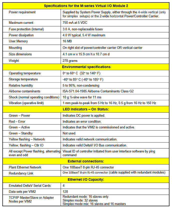
Hardware specifications
Category specific parameters
The power requirement is supplied by the DeltaV system power supply, supporting 2-wide horizontal carriers or 4-wide vertical carriers (single-mode configuration only)
Electrical protection built-in 3.0A non replaceable fuse, maximum current 750mA (5VDC)
Typical power consumption of 4.0W, maximum value of 5.4W
Storage and Size: User Memory 16MB; Size: 4.1cm (width) x 15.9cm (height) x 10.7cm (depth), Weight: 278g
Installation method: Install in the right slot (horizontal carrier) or vertical carrier of the power/controller carrier
Environmental parameters: Operating temperature: 0 ° C~60 ° C (32 ° F~140 ° F), Storage temperature: -40 ° C~85 ° C (-40 ° F~185 ° F); Relative humidity ranging from 5% to 95% (without condensation); The air pollutant level complies with ISA-S71.04-1985 G2 level; Shock resistance (normal operation): 10g half sine wave, continuous for 11ms; Vibration resistance (working limit): 1mm peak to peak value at 5Hz~16Hz, 0.5g at 16Hz~150Hz
LED indicator light - green (power): indicates connection to DC power supply
-Red (Error): Indicates the existence of an error status
-Green (Active): indicates that VIM2 has been debugged and is in an active state
-Green (Standby): Not used
-Yellow flashing (Network): indicates normal network communication
-Yellow flashing (Ctlr IO): indicates that DeltaV I/O bus communication is normal
-Alternating flashing (parity) except for the power light: device recognition triggered by the ping command on the user interface software
External Interface - Factory Ethernet: 1 10BaseT 8-pin RJ-45 connector
-Redundant link: 1 10BaseT 8-pin RJ-45 connector (redundant kit includes dedicated cable)
Ethernet I/O Capacity - Analog DeltaV Serial Card: 4
-Number of datasets: 128 per unit
-Number of device nodes: 32 single mode slave stations (or 16 master+16 slave stations), redundant 16 slave stations
DeltaV Authorization and Configuration Rules
DST counting rule: The DeltaV software authorization requirement (DST counting) for the VIM2 register is consistent with the serial card register - a single DeltaV serial card dataset can contain up to 100 values (Boolean, 8-bit/16 bit values), and if it is a floating-point or 32-bit value, it can contain up to 50 values; If a single dataset is referenced by only one module, it is counted as one DST; If referenced by multiple modules, the DST count is equal to the number of referenced modules.
DST type differentiation: The numerical count used to control the function block is "Control DST", and the numerical count used only for graphic display or historical data acquisition is SCADA value, not included in DST count.
- OMRON
- ABB
- General Electric
- EMERSON
- Honeywell
- HIMA
- ALSTOM
- Rolls-Royce
- MOTOROLA
- Rockwell
- Siemens
- Woodward
- YOKOGAWA
- FOXBORO
- KOLLMORGEN
- MOOG
- KB
- YAMAHA
- BENDER
- TEKTRONIX
- Westinghouse
- AMAT
- AB
- XYCOM
- Yaskawa
- B&R
- Schneider
- KONGSBERG
- NI
- WATLOW
- ProSoft
- SEW
- ADVANCED
- Reliance
- TRICONEX
- METSO
- MAN
- Advantest
- STUDER
- DANAHER MOTION
- Bently
- Galil
- EATON
- MOLEX
- DEIF
- B&W
- ZYGO
- Aerotech
- DANFOSS
- Beijer
- Moxa
- Rexroth
- Johnson
- WAGO
- TOSHIBA
- BMCM
- SMC
- HITACHI
- HIRSCHMANN
- Application field
- XP POWER
- CTI
- TRICON
- STOBER
- Thinklogical
- Horner Automation
- Meggitt
- Fanuc
- Baldor
- SHINKAWA
- Other Brands
- UniOP
- KUKA
- Iba
- Beckhoff
-
 OMRON B7AM-8B16 I/O Terminal Block
 -
 Fanuc A06B-6110-H026 Power Supply Module
 -
 Schneider TSXETG3021 Ethernet Gateway
 -
 OMRON CS1W-CLK21-V1 Controller Link Unit
 -
 NP1W6406T-Z704 PLC I/O Module
 -
 OMRON CJ1W-DA08C Analog Output Module
 -
 Yaskawa 3G3HV-A4022-CE AC Drive
 -
 OMRON NB7W-TW01B CP1L-EL20DR-D Power Panel
 -
 OMRON C500-NC103-E Position Control Unit
 -
 Steag Hamatech PLC DCS Servo Control System
 -
 Siemens 6SN1123-1AA00-0DA1 Power Supply Module
 -
 GE IC693CHS391H CPU & AD693CMM301A PLC Module
 -
 Siemens 6FC5303-0AF23-1AA1 PLC Control Panel
 -
 Square D CM4000T PowerLogic Circuit Monitor J1 F16
 -
 Siemens 6FX5002-5DG10-1BA0 MOTION-CONNECT 500 Cable
 -
 Schmersal SRB324ST 101195504 Safety Relay 24V
 -
 Mitsubishi 15050-PR02A PLC Circuit Board Module
 -
 OMRON CQM1-AD041 Analog Input PLC Module
 -
 Beckhoff EL5042 EtherCAT PLC Terminal Module
 -
 OMRON C200HW-MC402-E Motion Control Unit
 -
 C36TC0UA1100 Industrial Temperature Controller
 -
 NL8048BC24 12 Industrial Control LCD Module
 -
 OMRON R88D Servo Drive and Motor System
 -
 OMRON CS1W CLK21 V1 Controller Link Module
 -
 OMRON YASKAWA R7M A20030 S1 D Servo Motor
 -
 SIEMENS 6AV2128 3KB06 0AX1 Unified Comfort Panel
 -
 Schneider Electric METSEPM8240 PowerLogic Meter
 -
 Advanced AMCI 1PLC 1 31F Programmable Limit Switch
 -
 ABB PM582 ETH Programmable Logic Processor
 -
 SIEMENS 6FC5110 0CB01 0AA0 CPU Control Board
 -
 Schleicher P03GS13A CPU Module
 -
 Siemens 6SN1123-1AA00-0BA1 Power Module
 -
 Mitsubishi A1S61PN Power Supply Module
 -
 Yaskawa CPS-IONB DC Power Supply Module
 -
 Siemens 6ES7215-2BD00 CPU 215-2
 -
 Mitsubishi A2ACPU MELSEC PLC System Kit
 -
 ProSoft 3150-MCM Communication Module
 -
 Mitsubishi OSE104ET Incremental Encoder
 -
 OMRON CJ1W-AD081-V1 Analog Input Module
 -
 Broadcom BCM5464A1KRB Quad Port Ethernet IC
 -
 Modicon M221-24IO TM221C24 PLC 24 PNP Transistor
 -
 Allen-Bradley 1321-3R160-B Line Reactor 3R160B
 -
 Beckhoff CX1020-0012 Embedded PLC Module Specs
 -
 Turck BL20-PF-24VDC-D Power Feed Module Specs
 -
 Siemens 6SY7000-0AC37 Power Supply Module
 -
 Yaskawa SGDH-10DE-OY 1kW 400V Servo Drive Specs
 -
 Omron 3G3SV-BB015-E 1.5kW 220V VFD Specs
 -
 Uni-Pro CPU91-PLC J 23.020167X Processor Module
 -
 PASABAN MTC-3044 PLC Rack Power Supply 4835-A
 -
 XYCOM 3015T Operator Interface Panel BIN4.4.4
 -
 OMRON CJ1W-MD261 Mixed I/O Module
 -
 Omron NJ301-1100 PLC CPU eCat EIP Specs
 -
 Omron F500-C15-ETN Vision System PLC Module
 -
 Modicon M241-24IO TM/T2UK PLC with Ethernet
 -
 SIXNET YS-800-001 RTU PLC Module
 -
 BEMAC UST-202-D Interface Board 1307D V08B2
 -
 Yaskawa JANCD-MMOIC-02 Drive Circuit Board
 -
 ABB 3BSE005028R1 SDCS-COM-1 Comm Board
 -
 Omron 3G3MX2-A4110 A4150 Inverter Drives Specs
 -
 KEYENCE CA-E100 PLC Module
 -
 GE IC693ALG223-GB Analog Input Module Specs
 -
 ABB BAILEY IMMFP01 Multi Function Processor System
 -
 SIEMENS 6FC5372 0AA00 0AA1 NCU 7202 Controller
 -
Modicon TM241CE4 40I O Transistor Programmable Controller
-
 SIEMENS 6ES7 315 2EH13 0AB0 CPU 3152 PN DP
 -
 NORIS A1 91 PCB Card Rack Module System
 -
 SIEMENS 6ES7 313 5BE01 0AB0 Compact CPU
 -
 SCHNEIDER ELECTRIC S144B MICROLOGIC 60A Trip Unit
 -
 CNI PLC269 v3 Control Module Board Rev H
 -
ABB BAILEY IIMCP02 Processor Module
-
 OMRON NT20S ST121 EV3 Operator Interface Terminal
 -
 OMRON NS-CA001 Video Input Unit
 -
 GE Fanuc IC695CHS012 RX3i Backplane
 -
 Allen Bradley 2711E-K14C6 PanelView 1400e Terminal
 -
 Siemens Sinamics CCB 10000432.71 Power Cell
 -
 Siemens 6SL3210-1SE21-8UA0 Power Module PM340
 -
 Yaskawa CIMR-F7A20P4 AC Drive
 -
 Beckhoff EP1918-0002 EtherCAT Box I/O Module
 -
 OMRON CQM1-TC001 Temperature Control Module
 -
 GE Fanuc SGHA36AT0400 Industrial Contactor
 -
 OMRON NJ501-1500 PLC Machine Automation Controller
 -
 Mitsubishi MAZAK QX084 Power Supply MELDAS 500 CNC
 -
 B&R 0AC808.9 PLC Automation Module
 -
 OMRON CP1H-XA40DT1-D PLC Module
 -
 G&W Electric PLC15 5111 011 15kV Capnut Assembly
 -
 GE DS200SLCCG3AGH PCB Circuit Board
 -
 Siemens SINUMERIK 6FC3981-4FD PLC Extension
 -
 OMRON F300-DC I/O Image Processing Unit
 -
 FANUC A06B-0314-B002 AC Servo Motor
 -
 GC-S84 Programmable Controller Logic Module
 -
 PASABAN MONTELEC MTC3001-DC Drive Control PLC
 -
 Allen Bradley 100E460EJ11 Auxiliary Contactor
 -
 Bosch Rexroth 1070075337-101 Card Parameters
 -
 HMS Anybus AB7646-F Gateway Specifications
 -
 Bosch 062633-303401 CNC Servo PLC Card
 -
 TI 500-5023 Series PLC Power Supply
 -
 Siemens C98043-A7002-L1-12 Circuit Board
 -
 Omron E5CC-RX3A5M-000 Controller
 -
 CN-8032-L Profinet Network Adapter Module
 -
 Siemens 3TK2804-0BB4 Safety Relay Details
 -
 Toledo TTLM-2-1M I/O Load Module
 -
 NORIS A1-91 PLC Rack Board Specifications
 -
 Mitsubishi A3ACPUR21 MELSEC PLC CPU Module
 -
 Beckhoff EP7041‑3002 EtherCAT Box Digital Input Module
 -
 REER EOS2E 1053 EOS2R 1053 Safety Light Curtain
 -
 Mitsubishi Q80BD-J71BR11 MELSECNET/H Interface Board
 -
 Omron 3G3IV-B4220-EV2 VFD 400V 22kW
 -
 Allen-Bradley 96844671 1785-LT3 PLC-5/12 Processor Module
 -
 Pasaban MTC3001-DC Drive Control PLC Module
 -
 Omron CJ1M-CPU11 V4.0 PLC CPU Module
 -
 ABB CM579-PNIO B3 Communication Module
 -
 B&R X20 AI 4221 Analog Module
 -
 Siemens 6SY7000-0AC80 PLC Module
 -
 GE 531X300CCHAFM5 Control Card
 -
 AB 810-A15C Inverse Time Relay
 -
 WITTENSTEIN LP120X-MF2-20 Planetary Gear
 -
 Mitsubishi Kakoki E-01B-4130 PLC I/O Modules
 -
 ABB DSQC643 Safety Control Board
 -
 Siemens G26004-A2105-P100-2 PCB
 -
 OMRON F350-C10E Image Processing Unit
 -
 FUJI UG430H-TS1 HMI Touch Panel
 -
 Westronics CB100188-01 Rev F Board
 -
 Siemens 7MH4900-3AA01 Weighing Module
 -
 Gilbert & Nash Tracker 2000 Control Cabinet
 -
 OMRON CJ1M-CPU22 CPU Unit
 -
 OMRON F3SJ-E0625P25 Light Curtain
 -
 Siemens 3VA2340-5HL32-0AA0 Breaker
 -
 Mitsubishi Melsec A61P A2NCPU PLC System


