
Barber Colman MA41-7153-502 and similar series actuators
Key feature: Mechanical spring reset (clockwise/counterclockwise optional), ensuring reliable reset after power loss; 95 ° rotation stroke (can be limited by accessories to 30 ° -95 °); Visual position indicator; Overload protection during full rotation process; Some models come with built-in auxiliary switches for signal interaction or interlock control.
Barber Colman MA41-7153-502 and similar series actuators
Product core positioning and series differences
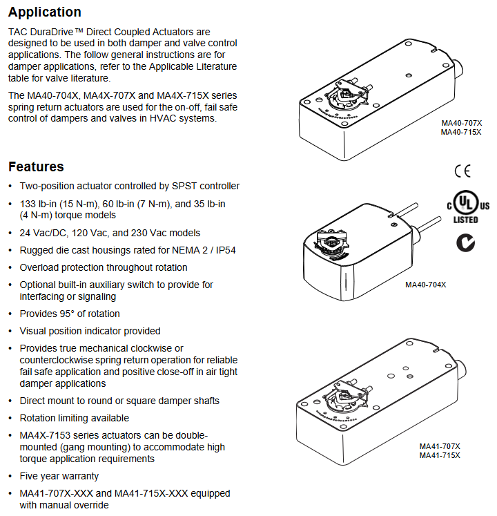
1. Core functions and applications
Purpose: Used for the "on-off" control and fail safe (power-off spring reset) operation of air doors and valves in HVAC systems, supporting direct coupling installation, and some models can be connected in parallel (linkage installation) to meet high torque requirements.
Key feature: Mechanical spring reset (clockwise/counterclockwise optional), ensuring reliable reset after power loss; 95 ° rotation stroke (can be limited by accessories to 30 ° -95 °); Visual position indicator; Overload protection during full rotation process; Some models come with built-in auxiliary switches for signal interaction or interlock control.
2. Differences in Series Models
The three major series are distinguished by torque level, voltage specifications, and additional functions, with the following core differences:
Series torque levels (lb in/N-m) voltage specifications core features auxiliary switch configuration manual override function
MA40-704X 35 (4) 24Vac/DC, 120Vac, 230Vac NEMA 2/IP54 protection (no installation restrictions), travel limiter standard with some models (-501) including 1 SPDT switch (0-95 ° adjustable) none
MA4X-707X 60 (7) 24Vac/DC, 120Vac, 230Vac NEMA 2/IP54 protection (requires downward installation of conduit), supports rotation restriction part models (-502) including 2 SPDT switches (1 fixed at 5 °, 1 adjustable at 25-85 °) MA41-707X series has (-5 ° to 85 ° adjustable)
MA4X-715X 133 (15) 24Vac/DC, 120Vac, 230Vac, same as MA4X-707X, with maximum torque, can be installed in parallel with two machines. Some models (-502) include two SPDT switches (one fixed at 5 ° and one adjustable at 25-85 °). The MA41-715X series has (-5 ° to 85 ° adjustable)
MA41-7153-502 Exclusive Attributes: Belonging to the MA4X-715X series, powered by 24Vac/DC, 133lb in (15N-m) torque, including 2 SPDT auxiliary switches, with manual override function, supporting dual machine parallel connection.
Key technical parameters
1. Electrical parameters
Specific specifications for parameter categories (taking MA41-7153-502 as an example, refer to Table 1 for other models)
Supply voltage 24Vac ± 20% or 22-30Vdc
Power consumption operation: 9.8VA (50Hz), 9.7VA (60Hz); Maintain: 7.5VA (50/60Hz)
Current running DC current 0.29A; locked rotor current 2.8A
2 SPDT auxiliary switches, resistive load 7A at 250Vac, inductive load 2.5A
Control signal single pole single throw (SPST) control contact or bidirectional thyristor (500mA rated)
Wiring 3-foot (91cm) equipment cable, 1/2-inch conduit interface (equipped with AM-756 convertible M20 metric conduit)
2. Mechanical and environmental parameters
Rotation stroke: Maximum 95 °± 5 °, MA40-704X series comes standard with a travel limiter, MA4X-707X/715X requires AM-689 accessories to achieve 30 ° -95 ° adjustment.
Wind door shaft adaptation:
MA40-704X: Standard fixture supports ≤ 5/8 inch (15mm) circular axis or ≤ 1/2 inch (13mm) square axis; AM-710 accessories support ≤ 3/4 inch (19mm) circular shafts.
MA4X-707X/715X: Standard fixture supports ≤ 3/4 inch (19mm) circular axis or ≤ 1/2 inch (13mm) square axis; AM-687 accessories support circular shafts ≤ 1.05 inches (27mm) or square shafts ≤ 5/8 inches (15mm).
Protection level: MA40-704X is NEMA 2/IP54; MA4X-707X/715X is NEMA 1/IP30 (NEMA 2/IP54 when the conduit is facing downwards).
Environmental conditions: Operating temperature -22 ° F to 140 ° F (-30 ° C to 60 ° C); Storage/transportation temperature -40 ° F to 160 ° F (-40 ° C to 71 ° C); Humidity 15% -95% RH (non condensing).
Certification: UL 873, CUL (Canada), CE (compliant with EMC/Low Voltage Directive), C-Tick Australia.
Installation specifications and operating procedures
1. Preparation before installation
Personnel requirements: It must be operated by qualified professional technicians who are familiar with national/local electrical regulations.
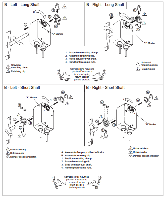
Tools and accessories: Please bring your own # 8 sheet metal screws, 10mm wrench, 7/16 inch wrench, 1/8 inch hex wrench, and screwdriver; Select the corresponding fixture based on the shaft diameter (such as AM-710, AM-687), and the installation method for the long axis (≥ 3.5 inches/90mm) and short axis (<3.5 inches/90mm) is different.
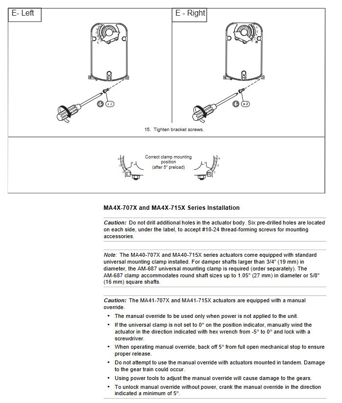
Safety warning: Disconnect the power supply before installation to prevent electric shock; Avoid approaching strong electromagnetic interference sources such as contactors and large motors; It is prohibited to drill holes in the actuator body (there are 6 pre drilled holes under the labels on both sides for accessory installation).
2. Core installation steps (divided into series)
(1) MA40-704X series
Wind door positioning: Adjust the wind door to the normal position (the indicator indicates 0 ° when the normally closed wind door is closed, and 0 ° when the normally open wind door is open), and confirm the direction of shaft rotation (clockwise/counterclockwise opening).
Fixture installation: For short shafts (<3.5 inches), the air door position indicator should be installed first, then the actuator should be inserted and the fixture nut should be manually tightened; Insert the long axis directly into the actuator and manually pre tighten the fixture.
Fixing and Calibration: After aligning the centerline, drill a hole to fix the bracket, loosen the clamp nut, rotate the actuator 5 ° in the direction of operation (without moving the shaft), then tighten the clamp nut with a torque of 4-6lb ft (5.4-8.2N-m), and finally fix the bracket screw.
(2) MA4X-707X/715X series (including MA41-7153-502)
The basic steps are the same as MA40-704X, but please note:
The conduit interface needs to be installed facing downwards to meet IP54 protection requirements;
MA41-707X/715X series with manual override: In the power-off state, use an Allen wrench to adjust the indicator to 0 ° and lock it. After installation, it will automatically unlock when powered on for the first time;
The tightening torque of the fixture is 8-10 lb ft (11-14 N-m), which is higher than the MA40-704X series.
3. Special installation scenarios
Dual machine parallel connection (linkage installation): AM-673 bracket is required, and all actuator L2 wires are connected to the transformer common terminal and L1 wires are connected to the live wire, ensuring consistent polarity and total current not exceeding the rated value of the transformer and control circuit.
Long axis/short axis adaptation: For shaft lengths ≥ 3.5 inches (90mm), use the long axis installation method; When using the short axis method for spaces smaller than 3.5 inches or when the space is narrow, an additional position indicator needs to be adapted.
Wiring and Debugging
1. Wiring specifications
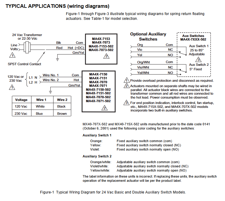
Voltage corresponds to line color: 24Vac/DC model (such as MA41-7153-502) L1=red, L2=black; 120Vac model L1=black, L2=white; 230Vac model L1=brown, L2=light blue (see Table 2 and Table 5 for details).
Auxiliary switch wiring: The two switches of MA4X-715X-502/MA4X-707X-502 are respectively "5 ° fixed" (purple/yellow/orange line) and "25-85 ° adjustable" (purple white/yellow white/orange white line), used for indicating the position of the air door end and interlocking the fan start.
Wiring requirements: Class 2 control/power lines should be wired separately from line voltage lines and non-Class 2 circuits; The auxiliary switch line needs to be connected to a Class 1 circuit.
2. Debugging and Inspection
Power on test: After power on, the actuator should drive the air door to the "power on position", and after power off, the spring should be reset to the "normal position". Repeat the test 3 times to confirm reliability.
Auxiliary switch verification: For models with suffix -501/-502, manually adjust the switch pointer to the target angle and power on to verify whether the on/off status of the switch meets the requirements.
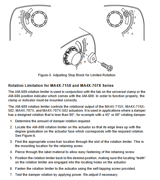
Rotation limit verification: If installing AM-689 (MA4X series) or using the built-in stroke limiter of MA40 series, it is necessary to test whether the rotation angle of the air door meets the design value (such as 45 °, 60 °) by powering on.
Operations and troubleshooting
1. Maintenance requirements
Daily maintenance: The actuator is designed to be maintenance free and does not require regular maintenance under normal use (in compliance with environmental and installation requirements). It only needs to be checked regularly by an electrician according to EN standards for the overall system status.
Manual override use: Only available in the MA41-707X/715X series. To operate when power is off, insert an Allen wrench into the override hole and rotate it to the target angle (-5 ° to 85 °). It is strictly prohibited to use it when powered on or in parallel with two machines (to avoid gear damage).
2. Troubleshooting
Possible causes and solutions for the fault phenomenon
Not functioning after power on: 1. The power supply is not properly connected or the voltage does not match; 2. The control contacts are not closed; 3. The fixture is too tight and stuck. 1. Check the wiring and voltage (e.g. 20-28Vac is required for 24Vac); 2. Confirm the continuity of SPST contacts; 3. Loosen the clamp nut and recalibrate the torque
1. Failure to reset due to power loss. Spring damage; 2. The air door is stuck; 3. The position of the rotation limiter is incorrect. 1. Replace the actuator; 2. Check the mechanical resistance of the air door; 3. Adjust the position of the limiter again
Auxiliary switch has no signal. 1. Wiring error; 2. The switch pointer is not aligned with the target angle; 3. The switch is damaged. 1. Check the wire color and wiring diagram; 2. Adjust the pointer again after power failure; 3. Replace the actuator
3. Disposal and Warranty
Scrap disposal: Metal, plastic, and electronic components must be disposed of in accordance with local regulations and can be returned to Barber Colman (shipping costs borne by the sender).
Warranty policy: The entire series is covered by a 5-year warranty, and damages caused by human factors (such as drilling or manual override during power on) are not covered by the warranty.
Key accessories and document references
1. Common accessories (adapted by series)
Adaptation series accessories, models, and purposes
MA40-704X AM-710 universal fixture compatible with ≤ 3/4 inch (19mm) circular shaft
MA40-704X AM-709 position indicator combined with travel limiter
MA4X-707X/715X AM-687 is compatible with fixtures for circular shafts ≤ 1.05 inches (27mm) or square shafts ≤ 5/8 inches (15mm)
MA4X-707X/715X AM-689 rotation limiter (adjust travel from 30 ° to 95 °)
Full series AM-673 dual machine parallel (linkage installation) bracket
Full series AM-756 M20 metric conduit to 1/2 inch NPT interface adapter
- OMRON
- ABB
- General Electric
- EMERSON
- Honeywell
- HIMA
- ALSTOM
- Rolls-Royce
- MOTOROLA
- Rockwell
- Siemens
- Woodward
- YOKOGAWA
- FOXBORO
- KOLLMORGEN
- MOOG
- KB
- YAMAHA
- BENDER
- TEKTRONIX
- Westinghouse
- AMAT
- AB
- XYCOM
- Yaskawa
- B&R
- Schneider
- KONGSBERG
- NI
- WATLOW
- ProSoft
- SEW
- ADVANCED
- Reliance
- TRICONEX
- METSO
- MAN
- Advantest
- STUDER
- DANAHER MOTION
- Bently
- Galil
- EATON
- MOLEX
- DEIF
- B&W
- ZYGO
- Aerotech
- DANFOSS
- Beijer
- Moxa
- Rexroth
- Johnson
- WAGO
- TOSHIBA
- BMCM
- SMC
- HITACHI
- HIRSCHMANN
- Application field
- XP POWER
- CTI
- TRICON
- STOBER
- Thinklogical
- Horner Automation
- Meggitt
- Fanuc
- Baldor
- SHINKAWA
- Other Brands
- UniOP
- KUKA
- Iba
- Beckhoff
-
 OMRON C60H C6DR DE V1 Sysmac PLC
 -
 MITSUBISHI ELECTRIC A2ACPU21 S1 CPU Module
 -
 ABB BAILEY INNPM12 Network Process Module
 -
 HONEYWELL 620 0073C IPC PLC Module
 -
 Mitsubishi 15050 PR02B PLC Circuit Board
 -
 SIEMENS 6SY7000 0AC37 Drive Control Module
 -
 OMRON TJ2 ECT16 Traxial EtherCAT Controller
 -
 GE Fanuc IC698PSD300D Power Supply Module
 -
 Texas Instruments Series 505 16 Position Base
 -
 OMRON YASKAWA SGDH 10DE OY Servo Drive
 -
 Allen‑Bradley 440G-MT Safety Interlock Switch Specs
 -
 Rubycon PD27A 24V 8A Power Supply Module
 -
 SK-H1-GDB1-F11D PLC Gate Driver Board Kit
 -
 VIPA 441-4UA14 451-4UA14 PLC Module Rack
 -
 Mitsubishi FX5U-80MT ESS PLC Controller Specs
 -
 Mitsubishi Q64TCRTN Temperature PLC Module
 -
 GE 1C31170G Rev10 PLC Circuit Board Module
 -
 Schneider TWDLMDA40DTK PLC Controller Module
 -
 Omron FQM1-MMA22 Motion Control Module Specs
 -
 OMRON CJ1W-NCF71 Position Control Unit Specs
 -
 Schneider TSXETY4103 Ethernet Module
 -
 Mitsubishi Q12PHCPU Process CPU
 -
 Yaskawa 3G3HV-A4022-CE AC Drive
 -
 Cincinnati Milacron 3-533-0669G Temperature Control Board
 -
 Allen Bradley 20AC030A3AYNANC0 PowerFlex 70 Drive
 -
 Siemens 6ES7314-6BG03-0AB0 CPU 314C-2 DP
 -
 Carrier 17EX54007903 PLC Module
 -
 OMRON CS1W-V600C12 ID Controller Module
 -
 Honeywell 51402755-100 PCB Card
 -
 Heidenhain ECN 113 Rotary Encoder
 -
 OMRON B7AM-8B16 I/O Terminal Block
 -
 Fanuc A06B-6110-H026 Power Supply Module
 -
 Schneider TSXETG3021 Ethernet Gateway
 -
 OMRON CS1W-CLK21-V1 Controller Link Unit
 -
 NP1W6406T-Z704 PLC I/O Module
 -
 OMRON CJ1W-DA08C Analog Output Module
 -
 Yaskawa 3G3HV-A4022-CE AC Drive
 -
 OMRON NB7W-TW01B CP1L-EL20DR-D Power Panel
 -
 OMRON C500-NC103-E Position Control Unit
 -
 Steag Hamatech PLC DCS Servo Control System
 -
 Siemens 6SN1123-1AA00-0DA1 Power Supply Module
 -
 GE IC693CHS391H CPU & AD693CMM301A PLC Module
 -
 Siemens 6FC5303-0AF23-1AA1 PLC Control Panel
 -
 Square D CM4000T PowerLogic Circuit Monitor J1 F16
 -
 Siemens 6FX5002-5DG10-1BA0 MOTION-CONNECT 500 Cable
 -
 Schmersal SRB324ST 101195504 Safety Relay 24V
 -
 Mitsubishi 15050-PR02A PLC Circuit Board Module
 -
 OMRON CQM1-AD041 Analog Input PLC Module
 -
 Beckhoff EL5042 EtherCAT PLC Terminal Module
 -
 OMRON C200HW-MC402-E Motion Control Unit
 -
 C36TC0UA1100 Industrial Temperature Controller
 -
 NL8048BC24 12 Industrial Control LCD Module
 -
 OMRON R88D Servo Drive and Motor System
 -
 OMRON CS1W CLK21 V1 Controller Link Module
 -
 OMRON YASKAWA R7M A20030 S1 D Servo Motor
 -
 SIEMENS 6AV2128 3KB06 0AX1 Unified Comfort Panel
 -
 Schneider Electric METSEPM8240 PowerLogic Meter
 -
 Advanced AMCI 1PLC 1 31F Programmable Limit Switch
 -
 ABB PM582 ETH Programmable Logic Processor
 -
 SIEMENS 6FC5110 0CB01 0AA0 CPU Control Board
 -
 Schleicher P03GS13A CPU Module
 -
 Siemens 6SN1123-1AA00-0BA1 Power Module
 -
 Mitsubishi A1S61PN Power Supply Module
 -
 Yaskawa CPS-IONB DC Power Supply Module
 -
 Siemens 6ES7215-2BD00 CPU 215-2
 -
 Mitsubishi A2ACPU MELSEC PLC System Kit
 -
 ProSoft 3150-MCM Communication Module
 -
 Mitsubishi OSE104ET Incremental Encoder
 -
 OMRON CJ1W-AD081-V1 Analog Input Module
 -
 Broadcom BCM5464A1KRB Quad Port Ethernet IC
 -
 Modicon M221-24IO TM221C24 PLC 24 PNP Transistor
 -
 Allen-Bradley 1321-3R160-B Line Reactor 3R160B
 -
 Beckhoff CX1020-0012 Embedded PLC Module Specs
 -
 Turck BL20-PF-24VDC-D Power Feed Module Specs
 -
 Siemens 6SY7000-0AC37 Power Supply Module
 -
 Yaskawa SGDH-10DE-OY 1kW 400V Servo Drive Specs
 -
 Omron 3G3SV-BB015-E 1.5kW 220V VFD Specs
 -
 Uni-Pro CPU91-PLC J 23.020167X Processor Module
 -
 PASABAN MTC-3044 PLC Rack Power Supply 4835-A
 -
 XYCOM 3015T Operator Interface Panel BIN4.4.4
 -
 OMRON CJ1W-MD261 Mixed I/O Module
 -
 Omron NJ301-1100 PLC CPU eCat EIP Specs
 -
 Omron F500-C15-ETN Vision System PLC Module
 -
 Modicon M241-24IO TM/T2UK PLC with Ethernet
 -
 SIXNET YS-800-001 RTU PLC Module
 -
 BEMAC UST-202-D Interface Board 1307D V08B2
 -
 Yaskawa JANCD-MMOIC-02 Drive Circuit Board
 -
 ABB 3BSE005028R1 SDCS-COM-1 Comm Board
 -
 Omron 3G3MX2-A4110 A4150 Inverter Drives Specs
 -
 KEYENCE CA-E100 PLC Module
 -
 GE IC693ALG223-GB Analog Input Module Specs
 -
 ABB BAILEY IMMFP01 Multi Function Processor System
 -
 SIEMENS 6FC5372 0AA00 0AA1 NCU 7202 Controller
 -
Modicon TM241CE4 40I O Transistor Programmable Controller
-
 SIEMENS 6ES7 315 2EH13 0AB0 CPU 3152 PN DP
 -
 NORIS A1 91 PCB Card Rack Module System
 -
 SIEMENS 6ES7 313 5BE01 0AB0 Compact CPU
 -
 SCHNEIDER ELECTRIC S144B MICROLOGIC 60A Trip Unit
 -
 CNI PLC269 v3 Control Module Board Rev H
 -
ABB BAILEY IIMCP02 Processor Module
-
 OMRON NT20S ST121 EV3 Operator Interface Terminal
 -
 OMRON NS-CA001 Video Input Unit
 -
 GE Fanuc IC695CHS012 RX3i Backplane
 -
 Allen Bradley 2711E-K14C6 PanelView 1400e Terminal
 -
 Siemens Sinamics CCB 10000432.71 Power Cell
 -
 Siemens 6SL3210-1SE21-8UA0 Power Module PM340
 -
 Yaskawa CIMR-F7A20P4 AC Drive
 -
 Beckhoff EP1918-0002 EtherCAT Box I/O Module
 -
 OMRON CQM1-TC001 Temperature Control Module
 -
 GE Fanuc SGHA36AT0400 Industrial Contactor
 -
 OMRON NJ501-1500 PLC Machine Automation Controller
 -
 Mitsubishi MAZAK QX084 Power Supply MELDAS 500 CNC
 -
 B&R 0AC808.9 PLC Automation Module
 -
 OMRON CP1H-XA40DT1-D PLC Module
 -
 G&W Electric PLC15 5111 011 15kV Capnut Assembly
 -
 GE DS200SLCCG3AGH PCB Circuit Board
 -
 Siemens SINUMERIK 6FC3981-4FD PLC Extension
 -
 OMRON F300-DC I/O Image Processing Unit
 -
 FANUC A06B-0314-B002 AC Servo Motor
 -
 GC-S84 Programmable Controller Logic Module
 -
 PASABAN MONTELEC MTC3001-DC Drive Control PLC
 -
 Allen Bradley 100E460EJ11 Auxiliary Contactor
 -
 Bosch Rexroth 1070075337-101 Card Parameters
 -
 HMS Anybus AB7646-F Gateway Specifications
 -
 Bosch 062633-303401 CNC Servo PLC Card
 -
 TI 500-5023 Series PLC Power Supply
 -
 Siemens C98043-A7002-L1-12 Circuit Board
 -
 Omron E5CC-RX3A5M-000 Controller


