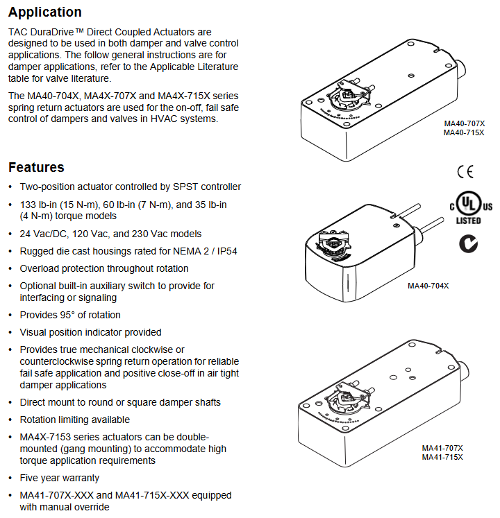
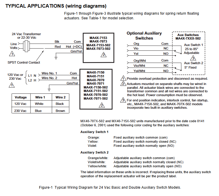
Barber Colman MA41-7153-502 and similar series actuators
Key feature: Mechanical spring reset (clockwise/counterclockwise optional), ensuring reliable reset after power loss; 95 ° rotation stroke (can be limited by accessories to 30 ° -95 °); Visual position indicator; Overload protection during full rotation process; Some models come with built-in auxiliary switches for signal interaction or interlock control.
Barber Colman MA41-7153-502 and similar series actuators
Product core positioning and series differences
1. Core functions and applications
Purpose: Used for the "on-off" control and fail safe (power-off spring reset) operation of air doors and valves in HVAC systems, supporting direct coupling installation, and some models can be connected in parallel (linkage installation) to meet high torque requirements.
Key feature: Mechanical spring reset (clockwise/counterclockwise optional), ensuring reliable reset after power loss; 95 ° rotation stroke (can be limited by accessories to 30 ° -95 °); Visual position indicator; Overload protection during full rotation process; Some models come with built-in auxiliary switches for signal interaction or interlock control.
2. Differences in Series Models
The three major series are distinguished by torque level, voltage specifications, and additional functions, with the following core differences:
Series torque levels (lb in/N-m) voltage specifications core features auxiliary switch configuration manual override function
MA40-704X 35 (4) 24Vac/DC, 120Vac, 230Vac NEMA 2/IP54 protection (no installation restrictions), travel limiter standard with some models (-501) including 1 SPDT switch (0-95 ° adjustable) none
MA4X-707X 60 (7) 24Vac/DC, 120Vac, 230Vac NEMA 2/IP54 protection (requires downward installation of conduit), supports rotation restriction part models (-502) including 2 SPDT switches (1 fixed at 5 °, 1 adjustable at 25-85 °) MA41-707X series has (-5 ° to 85 ° adjustable)
MA4X-715X 133 (15) 24Vac/DC, 120Vac, 230Vac, same as MA4X-707X, with maximum torque, can be installed in parallel with two machines. Some models (-502) include two SPDT switches (one fixed at 5 ° and one adjustable at 25-85 °). The MA41-715X series has (-5 ° to 85 ° adjustable)
MA41-7153-502 Exclusive Attributes: Belonging to the MA4X-715X series, powered by 24Vac/DC, 133lb in (15N-m) torque, including 2 SPDT auxiliary switches, with manual override function, supporting dual machine parallel connection.

Key technical parameters
1. Electrical parameters
Specific specifications for parameter categories (taking MA41-7153-502 as an example, refer to Table 1 for other models)
Supply voltage 24Vac ± 20% or 22-30Vdc
Power consumption operation: 9.8VA (50Hz), 9.7VA (60Hz); Maintain: 7.5VA (50/60Hz)
Current running DC current 0.29A; locked rotor current 2.8A
2 SPDT auxiliary switches, resistive load 7A at 250Vac, inductive load 2.5A
Control signal single pole single throw (SPST) control contact or bidirectional thyristor (500mA rated)
Wiring 3-foot (91cm) equipment cable, 1/2-inch conduit interface (equipped with AM-756 convertible M20 metric conduit)
2. Mechanical and environmental parameters
Rotation stroke: Maximum 95 °± 5 °, MA40-704X series comes standard with a travel limiter, MA4X-707X/715X requires AM-689 accessories to achieve 30 ° -95 ° adjustment.
Wind door shaft adaptation:
MA40-704X: Standard fixture supports ≤ 5/8 inch (15mm) circular axis or ≤ 1/2 inch (13mm) square axis; AM-710 accessories support ≤ 3/4 inch (19mm) circular shafts.
MA4X-707X/715X: Standard fixture supports ≤ 3/4 inch (19mm) circular axis or ≤ 1/2 inch (13mm) square axis; AM-687 accessories support circular shafts ≤ 1.05 inches (27mm) or square shafts ≤ 5/8 inches (15mm).
Protection level: MA40-704X is NEMA 2/IP54; MA4X-707X/715X is NEMA 1/IP30 (NEMA 2/IP54 when the conduit is facing downwards).
Environmental conditions: Operating temperature -22 ° F to 140 ° F (-30 ° C to 60 ° C); Storage/transportation temperature -40 ° F to 160 ° F (-40 ° C to 71 ° C); Humidity 15% -95% RH (non condensing).
Certification: UL 873, CUL (Canada), CE (compliant with EMC/Low Voltage Directive), C-Tick Australia.

Installation specifications and operating procedures
1. Preparation before installation
Personnel requirements: It must be operated by qualified professional technicians who are familiar with national/local electrical regulations.
Tools and accessories: Please bring your own # 8 sheet metal screws, 10mm wrench, 7/16 inch wrench, 1/8 inch hex wrench, and screwdriver; Select the corresponding fixture based on the shaft diameter (such as AM-710, AM-687), and the installation method for the long axis (≥ 3.5 inches/90mm) and short axis (<3.5 inches/90mm) is different.
Safety warning: Disconnect the power supply before installation to prevent electric shock; Avoid approaching strong electromagnetic interference sources such as contactors and large motors; It is prohibited to drill holes in the actuator body (there are 6 pre drilled holes under the labels on both sides for accessory installation).
2. Core installation steps (divided into series)
(1) MA40-704X series
Wind door positioning: Adjust the wind door to the normal position (the indicator indicates 0 ° when the normally closed wind door is closed, and 0 ° when the normally open wind door is open), and confirm the direction of shaft rotation (clockwise/counterclockwise opening).
Fixture installation: For short shafts (<3.5 inches), the air door position indicator should be installed first, then the actuator should be inserted and the fixture nut should be manually tightened; Insert the long axis directly into the actuator and manually pre tighten the fixture.
- ABB
- General Electric
- EMERSON
- Honeywell
- HIMA
- ALSTOM
- Rolls-Royce
- MOTOROLA
- Rockwell
- Siemens
- Woodward
- YOKOGAWA
- FOXBORO
- KOLLMORGEN
- MOOG
- KB
- YAMAHA
- BENDER
- TEKTRONIX
- Westinghouse
- AMAT
- AB
- XYCOM
- Yaskawa
- B&R
- Schneider
- Kongsberg
- NI
- WATLOW
- ProSoft
- SEW
- ADVANCED
- Reliance
- TRICONEX
- METSO
- MAN
- Advantest
- STUDER
- KONGSBERG
- DANAHER MOTION
- Bently
- Galil
- EATON
- MOLEX
- DEIF
- B&W
- ZYGO
- Aerotech
- DANFOSS
- Beijer
- Moxa
- Rexroth
- Johnson
- WAGO
- TOSHIBA
- BMCM
- SMC
- HITACHI
- HIRSCHMANN
- Application field
- XP POWER
- CTI
- TRICON
- STOBER
- Thinklogical
- Horner Automation
- Meggitt
- Fanuc
- Baldor
- SHINKAWA
- Other Brands


