
STOBER POSIDRIVE ® How to install MDS 5000?
STOBER POSIDRIVE ® MDS 5000 installation method
Overview
This document is the fifth generation inverter product POSIDRIVE from STOBER company ® The installation manual for MDS 5000, version V 5.3 01/2008, covers core content such as safety instructions, technical parameters, mechanical installation, electrical installation, wiring allocation, connection examples, and accessories. It is suitable for professional technicians to install, debug, and maintain equipment, providing comprehensive guidance to ensure safe and stable operation of the equipment.
Safety instructions
(1) Definition of Security Level
Risk Description of Safety Signs
If you do not pay attention to this prompt, unexpected results or states may occur
CAUTION (no warning triangle) may cause property damage if appropriate preventive measures are not taken
CAUTION (with warning triangle) may cause minor personal injury and property damage if appropriate precautions are not taken
Warning: If appropriate preventive measures are not taken, there may be significant risks of death, serious personal injury, and significant property damage
If DANGER does not take appropriate preventive measures, it will inevitably result in life-threatening situations and significant property damage
NOTE: Important product information or document sections that require special attention
ACTION describes the particularly important steps in product operation
(2) Hardware security requirements
Device Attributes and Compliance: POSIDRIVE ® The FDS and MDS series are power electronic and electrical components used for energy flow regulation in high-voltage systems. They only supply power to servo motors (MDS) and asynchronous motors (FDS, MDS). Their use, installation, operation, and maintenance must comply with current regulations, legal requirements, applicable standards, and this technical document. They belong to the restricted sales category products specified in IEC 61800-3 and may cause high-frequency interference in residential areas. Users need to take appropriate measures.
High voltage safety: It is strictly prohibited to open the casing or disconnect the connection when the equipment is live; When installing or disassembling the option board, the device must be powered off (all power plugs disconnected) and wait for at least 5 minutes before operation; The equipment must be properly configured and installed in order to function properly. Transportation, installation, debugging, and operation are only allowed to be carried out by qualified personnel who have received specialized training.
Grounding and Protection: The equipment protection level is protective grounding, and the protective conductor must be connected according to regulations. It cannot operate directly on the IT network; Installation work can only be carried out in a power-off state. When working on the transmission system, it is necessary to lock the enable and disconnect the entire transmission system power supply (following 5 safety rules); Even without using DC link coupling, it is necessary to maintain its plug connection (BG0-BG2: X22); If the discharge time of the DC link capacitor exceeds 5 minutes, it is forbidden to insert any object into the interior of the equipment to avoid short circuits or equipment failures.
Environmental and installation regulations: When installing or performing other work inside the switchgear, the equipment must be protected from falling parts (such as wires, stranded wires, metal fragments, etc.); Before debugging, additional coverings need to be removed to prevent the equipment from overheating; The equipment needs to be installed inside the switchgear, and the ambient temperature should not exceed the specified technical parameter values; Only copper wire can be used, and the cross-sectional area of the wire must comply with the requirements of 60 ° C or 75 ° C in NEC standard 310-16 table.
Motor protection and circuit limitations: The motor must be equipped with an overall temperature monitor (basic insulation) that complies with EN 61800-5-1, or use external motor overload protection; The equipment is only suitable for power supply networks with a maximum symmetrical rated short-circuit current not exceeding 5000A (480V); Built in solid-state short-circuit protection does not provide branch circuit protection. Branch circuit protection should be provided according to the manufacturer's instructions, national electrical specifications, and local additional specifications. When using RK1 level fuses (see technical parameters section), it is suitable for circuits with a maximum root mean square symmetrical current of 10kA and 480V.
(3) Software Usage Specification
POSITool software permissions: This software package is used for application selection, parameter adjustment, and signal monitoring of STOBER fifth generation inverters. The copyright belongs to STOBER ANTRIEBSTECHNIK GmbH+Co. KG, and users are only authorized to use it. The software is only provided in machine-readable format; Customers who legally obtain the software may obtain non exclusive usage rights, which can be used for the above functions, and to support such use, make and install copies of the software (including one backup copy), all copies must retain copyright and other ownership notices.
Software usage restrictions: Customers are not allowed to use, copy, modify, transmit/transfer the software beyond the scope of the license, and are not allowed to perform reverse assembly, reverse compilation, or other conversion operations on the software. They are also not allowed to sublicense, rent, or lease the software.
Product maintenance scope: STOBER only assumes maintenance obligations for the last two current program versions prepared and released for use, and may choose to correct program errors or provide new versions; If the error cannot be corrected immediately, a temporary solution will be provided (which may require users to comply with special operating procedures); The right to correct errors can only be claimed when the reported errors are reproducible or can be recorded through machine output, and are reported in reproducible form and provide useful information for error correction; STOBER does not assume the obligation to correct errors in programs modified or tampered with by customers, unless the customer can prove that the error is not related to tampering; STOBER needs to store the current valid program version in a special protected location (fireproof data safe, bank vault).
Technical parameters
(1) Model Interpretation
Taking "MDS 5075/L" as an example, "MDS" is the product series, "5" represents the fifth generation, "075" represents a power of 7.5kW, "/L" represents the auxiliary voltage of the control electronic device as external 24V ("/H" represents the auxiliary voltage as DC link).
(2) General electrical parameters
Parameter Value
Under the rated maximum ambient air temperature data of 0-45 ° C, it can reach 55 ° C when the power is reduced by 2.5%/° C
Relative humidity during operation is 85%, with no condensation
Installation altitude below 1000m without restrictions, power reduction of 1.5%/100m from 1000-2000m
High voltage category complies with Class III of EN 61800-5-1
Pollution level meets level 2 of EN 60204/EN 50178
Protection level IP 20
The installation position is usually vertical installation
Ventilation method with built-in fan
Maximum voltage limit 830V
Brake chopper disabled voltage 740V/760V
(3) Detailed parameters of each specification and model
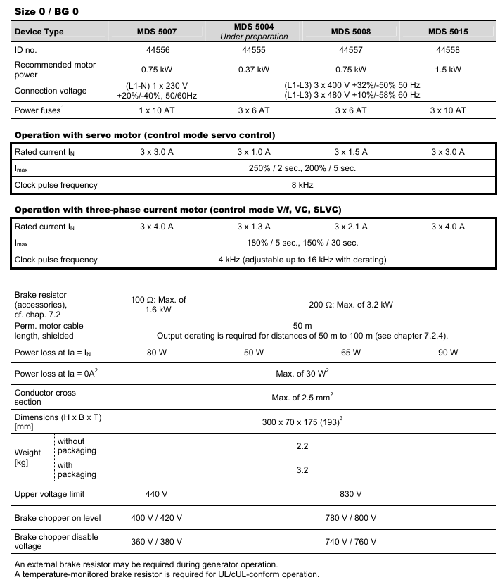
1. Specification 0/BG0
Equipment model MDS 5007 (ID: 44556) MDS 5004 (under preparation, ID:44555) MDS 5008(ID:44557) MDS 5015(ID:44558)
Recommended motor power 0.75kW 0.37kW 0.75kW 1.5kW
Connection voltage 1 × 230V (L1-N),+20%/-40%, 50/60Hz 3 × 400V (L1-L3),+32%/-50%, 50Hz; 3 × 480V (L1-L3),+10%/-58%, 60Hz Same as MDS 5004 Same as MDS 5004
Power fuse 1 × 10AT 3 × 6AT 3 × 6AT 3 × 10AT
Servo motor operation (servo control mode) - rated current (IN) 3 × 3.0A 3 × 1.0A 3 × 1.5A 3 × 3.0A
Servo motor operation (servo control mode) - maximum overload of 250%/2 seconds, 200%/5 seconds same as left, same as left
Servo Motor Operation (Servo Control Mode) - Clock Pulse Frequency 8kHz Same Left Same Left Same Left
Three phase current motor operation (V/f, VC, SLVC control mode) - rated current (IN) 3 × 4.0A 3 × 1.3A 3 × 2.1A 3 × 4.0A
Three phase current motor operation (V/f, VC, SLVC control mode) - maximum overload of 180%/5 seconds, 150%/30 seconds same as left, same as left, same as left
Three phase current motor operation (V/f, VC, SLVC control mode) - clock pulse frequency 4kHz (adjustable to 16kHz during derating) same as left, same as left, same as left
Braking resistor (accessories, see Chapter 7.2) 100 Ω: maximum 1.6kW, same as left 200 Ω: maximum 3.2kW, same as left
The allowed length of shielded motor cable is 50m, and the rating for 50-100m needs to be reduced (see Chapter 7.2.44). Same as left, same as left
When Ia=IN, the power consumption is 80W, 50W, 65W, and 90W
When Ia=0A, the maximum power consumption is 30W (depending on the connected option board and sensor, such as encoder), same as left, same as left
The maximum cross-sectional area of the wire is 2.5mm ², same left, same left, same left
Dimensions (H × B × T) [mm] 300 × 70 × 175 (193) (including depth of braking resistor RB 5000) Same as left, same as left
Weight [kg] (Unpackaged/Packaged) 2.2/3.2 Same Left Same Left Same Left
Maximum voltage limit 440V 830V Same Left Same Left
Brake chopper opening level 400V/420V 780V/800V same left same left
Brake chopper disable voltage 360V/380V 740V/760V same left same left
2. Specification 1/BG1
Parameter Value
Connection voltage 3 × 400V (L1-L3),+32%/-50%, 50Hz; 3×480V(L1-L3),+10%/-58%,60Hz
Power fuse 3 × 20AT
Servo motor operation (servo control mode) - rated current (IN) 3 × 10A
Servo motor operation (servo control mode) - maximum overload of 250%/2 seconds, 200%/5 seconds
Servo motor operation (servo control mode) - clock pulse frequency 8kHz
Three phase current motor operation (V/f, VC, SLVC control mode) - clock pulse frequency 4kHz (adjustable to 16kHz during derating)
Braking resistor (accessory) Ω: maximum 6.4kW
Power consumption (IN) 170W, 200W
Power consumption (Ia=0A) up to 30W (depending on the connected option board and sensor, such as encoder)
The maximum cross-sectional area of the wire is 4mm ²
Maximum voltage limit 830V
Brake chopper opening level 780V/800V
Brake chopper disabled voltage 740V/760V
3. Specification 2/BG2
Parameter Value
Connection voltage 3 × 400V (L1-L3),+32%/-50%, 50Hz; 3×480V(L1-L3),+10%/-58%,60Hz
Power fuse 3 × 50AT
Servo motor operation (servo control mode) - rated current (IN) 3 × 20A
Servo motor operation (servo control mode) - maximum overload of 250%/2 seconds, 200%/5 seconds
Servo motor operation (servo control mode) - clock pulse frequency 8kHz
Three phase current motor operation (V/f, VC, SLVC control mode) - clock pulse frequency 4kHz (adjustable to 16kHz during derating)
Braking resistor (accessory) 22 Ω: maximum 29kW
Power consumption (IN) 280W
Power consumption (Ia=0A) up to 30W (depending on the connected option board and sensor, such as encoder)
The maximum cross-sectional area of the wire is 6mm ²
Weight (unpackaged) 6.1kg
Maximum voltage limit 830V
Brake chopper opening level 780V/800V
Brake chopper disabled voltage 740V/760V
4. Specification 3/BG3
Equipment model MDS 5220 (ID: 44564) MDS 5370 (ID: 44566) MDS 5450 (ID: 44567)
Recommended motor power: 22kW, 37kW, 45kW
Connection voltage 3 × 400V (L1-L3),+32%/-50%, 50Hz; 3 × 480V (L1-L3),+10%/-58%, 60Hz same left same left
Power fuse 3 × 50AgG ² 3 × 80AgG ²-
Servo motor operation (servo control mode) - rated current (IN) 3 × 30A 3 × 50A 3 × 60A
Servo motor operation (servo control mode) - maximum overload of 250%/2 seconds, 200%/5 seconds ³ (average effective current within 10 minutes must not exceed rated current) Same left and same left
Servo Motor Operation (Servo Control Mode) - Clock Pulse Frequency 8kHz Same Left Same Left
Three phase current motor operation (V/f, VC, in preparation: SLVC control mode) - rated current (IN) 3 × 44A 3 × 70A 3 × 85A
Three phase current motor operation (V/f, VC, in preparation: SLVC control mode) - maximum overload of 180%/5 seconds, 150%/30 seconds ³ (average effective current within 10 minutes must not exceed rated current) same as left and right
Three phase current motor operation (V/f, VC, in preparation: SLVC control mode) - clock pulse frequency 4kHz (adjustable to 16kHz during derating) same left and same left
Internal braking resistor 30 Ω: 100W/maximum 21kW Same Left Same Left
External braking resistor (accessories, see Chapter 7.2) 15 Ω: maximum 42kW, same left, same left
Allowable shielded motor cable length of 100m, same left and same left
When Ia=IN, the power consumption is about 350W, about 600W, and about 1000W
When Ia=0A, the maximum power consumption is 55W ⁴ (depending on the connected option board and sensor, such as encoder). Same as left
When there is no core end sleeve in the cross-section of the wire, the maximum area is 35mm ², same left and same left
Dimensions (H × B × T) [mm] 382.5 × 190 × 276 Same Left Same Left
Weight [kg] (unpackaged/packaged) 11.8/13.6 13.2/15.0 13.2/15.0
The maximum voltage limit is 830V, same left and same left
The opening level of the brake chopper is 780V/800V, which is the same as the left
Brake chopper disable voltage 740V/760V same left same left
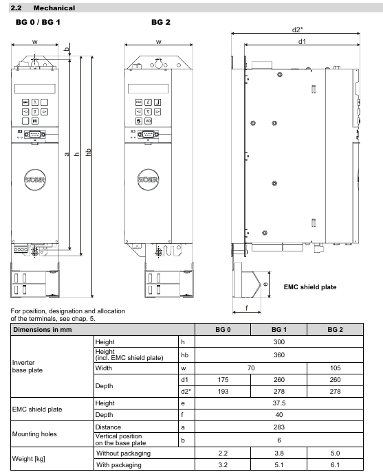
(4) Mechanical parameters
1. BG0/BG1/BG2
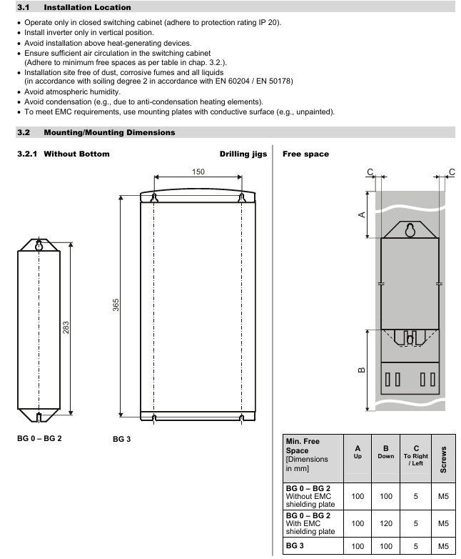
Parameter Value
Minimum free space without EMC shielding board [mm] (up/down/right/left) 100/100/5/5
Minimum free space with EMC shielding board [mm] (up/down/right/left) 100/120/5/5
Screw specification M5
2. BG3
Parameter Value
Height [mm] 382.5
Inverter substrate width [mm] 190
Inverter substrate depth [mm] 276
Vertical distance [mm] 365
Number of vertical mounting holes on the substrate: 6
Horizontal distance [mm] 150
Minimum free space [mm] (up/down/right/left) 100/100/5/5
Screw specification M5
Installation points
(1) Mechanical installation
Position requirement: Install vertically inside the enclosed switchgear, leaving a minimum free space (100mm up/down, 5mm left/right; 120mm below with EMC shielding board).
Accessory installation: Before installing the optional modules (fieldbus, I/O terminals), power off and discharge are required, and touching the gold-plated contacts is prohibited; The depth of the bottom braking resistor (RB 5000) is increased by about 20mm, and the EMC shielding board can be replaced with a 24V braking module.
(2) Electrical installation
EMC measures: Separate power lines from signal lines, use shielded wires for motor cables with a large area of shielding layer, and shield brake resistor cables exceeding 30cm.
Power and protection: Use RK1 level fuses (such as Bussmann KTS-R series), and choose 300/500mA or delayed RCD circuit breakers.
DC link coupling: Only three-phase equipment can be coupled, and parameter A38 (set 1 for group 2/3) needs to be set. In case of a fault, the entire power supply needs to be disconnected, and fuses need to be replaced in pairs.
Safe torque shutdown: achieved through the ASP 5001 option, requiring dual shutdown (enable+option), with at least one functional test per month.
Connection Example
(1) Universal Connection Example
1. Connect the 24V DC brake with BRM 5000
Including power fuse, power cut-off, PE, 24V/0V power supply, BRM 5000 module (X300, X302), MDS 5000 X10 power supply, X11 24V, X1 enable, X2 terminal, X20 motor, X21 braking resistor, X4 encoder and other connection methods, marked with only/L optional equipment, DC brake motor only, brake resistor if necessary, shielding for line length>300mm and other precautions.
2. Connect 230V AC brake using interface relay
Similar to the connection with the 24V DC brake, but the 230V AC brake is controlled through an interface relay, with relevant options, motor types, brake resistor usage, and cable shielding requirements also indicated.
3. Connect the brake using Powerbox
Including power fuses, power cut-off, Powerbox module, and MDS 5000 terminal connections, labeled with options, motor types, brake resistor usage, and cable shielding requirements.
(2) Terminal connection example
Example 1
The potentiometer on AE1 (terminals X100.1, X100.3, X100.8) is powered by 18V voltage (terminal X100.19) and a voltage divider; The potentiometer on AE2 (terminals X100.4, X100.5, X100.8) provides 10V voltage through AA1 and F41 analog outputs (offset=10V, terminal X100.6); 24V power supply including option board (BA).
Example 2
Stable current analog input AE1 (terminal X100.1-3); Voltage controlled analog input AE2 (terminals X100.4, X100.5); Analog output connected to PLC (terminal X100.6-8).
Accessory selection
Core accessories: EMC shielding board (EM 5000), 24V braking module (BRM 5000), expansion I/O terminal (XEA 5001), fieldbus module (CAN5000/ECS5000).
Braking resistor: Select according to specifications (e.g. RB 5200 200 Ω for BG0, FGFT 6000W 20 Ω for BG3), UL certification requires thermal monitoring type.
- OMRON
- ABB
- General Electric
- EMERSON
- Honeywell
- HIMA
- ALSTOM
- Rolls-Royce
- MOTOROLA
- Rockwell
- Siemens
- Woodward
- YOKOGAWA
- FOXBORO
- KOLLMORGEN
- MOOG
- KB
- YAMAHA
- BENDER
- TEKTRONIX
- Westinghouse
- AMAT
- AB
- XYCOM
- Yaskawa
- B&R
- Schneider
- KONGSBERG
- NI
- WATLOW
- ProSoft
- SEW
- ADVANCED
- Reliance
- TRICONEX
- METSO
- MAN
- Advantest
- STUDER
- DANAHER MOTION
- Bently
- Galil
- EATON
- MOLEX
- DEIF
- B&W
- ZYGO
- Aerotech
- DANFOSS
- Beijer
- Moxa
- Rexroth
- Johnson
- WAGO
- TOSHIBA
- BMCM
- SMC
- HITACHI
- HIRSCHMANN
- Application field
- XP POWER
- CTI
- TRICON
- STOBER
- Thinklogical
- Horner Automation
- Meggitt
- Fanuc
- Baldor
- SHINKAWA
- Other Brands
- UniOP
- KUKA
- Iba
- Beckhoff
- ADLINK
-
 Basler IFM-105 Firing Circuit Chassis 9324100105
 -
 Basler SR4A2B05B3A Static Voltage Regulator
 -
 Basler BE151G1EB6PB0N0F Protective Relay
 -
 Basler BE1-59 Electric Over Voltage Relay
 -
 Basler 277 Static Programmable Powerline Carrier Channel
 -
 Basler BE1-32R D1E A1P A0N1F Power Relay
 -
Basler SR4A1B07B3A Static Voltage Regulator
-
 Basler Electric BE1-700 Digital Protective Relay
 -
Basler Electric SR8A-2B01B3A Static Voltage Regulator
-
 Basler Electric SR4A-2B01B3E Static Voltage Regulator
 -
 Basler Electric 9017709102 PC Board
 -
Basler Electric SR4A-2B01B3A Static Voltage Regulator
-
 Basler Electric PRS-250 Veri-Sync Relay
 -
 Basler Electric 9066800102 Excitation Support System
 -
Basler Electric BE1-87G Generator Differential Relay 9 1708 18 100
-
 Basler Electric 36T865-2 BE03752001 Power Supply
 -
 Basler Electric M-300 149D940G02 Power Supply
 -
 Basler Electric ACA2040-25GM 4Mp 25Fps Area Scan Camera
 -
 Basler BE1-87G-S1A-A1C-A0N0 Differential Relay
 -
 Basler SR8A-2B06B3E Static Regulator SR8A2B06B3E
 -
 Basler SCP-210 Frequency Controller 9095400100
 -
 Basler BE1-59-A3E-A1J-N1N3F Overvoltage Relay BE159A3EA1JN1N3F
 -
 Basler 9 2011 11 100 Bracket Mounted Terminal Unit
 -
Basler 9 1606 00 101 Voltage Regulator
-
 Basler CBS-377 Current Boost System 9109600102
 -
 Basler 8650C72 Exciter Control Module PCB Rev 5
 -
 Basler C2EE1PA0N1F BE1-32R Reverse Power Relay
 -
 ADLINK HPCI-14S12U - Industrial Control Backplane 12PCI Backplane PCI-14S Passive Backplane
 -
-0010.png) ADLINK PCIe-GIE74C - image acquisition card 4-CH GigE Vision PoE+ Frame Grabber
ADLINK PCIe-GIE74C - image acquisition card 4-CH GigE Vision PoE+ Frame Grabber -
-0010_1.png) ADLINK PCI-8164 - control card 4-Axis Advanced Motion Controller Board
ADLINK PCI-8164 - control card 4-Axis Advanced Motion Controller Board -
 ADLINK PCIe-U304 - 4 Port USB3 PCIe Frame Grabbers USB Screw Hole Card
 -
 ADLINK PCI-9112 - Multi-Function Data Acquisition Card DAQ Card
 -
 ADLINK PCI-7432 - 51-12013-0A50 4-CH Isolated Numérique I/O PCI Cartes Digital I/O Card
 -
 ADLINK PCA-6106P3-0C1 REV.C1 - backplane 6-Slot Passive Backplane Board
 -
 ADLINK PCI-7224 - 24-CH Opto-Isolated Digital I/O PCI Board
 -
 ADLINK CPCI-7433R(G) - Digital Input Board Rear I/O CompactPCI Card
 -
 ADLINK EBP-13E4 - 51-46703-0A30 Industrial PC Backplane Passive Backplane
 -
 ADLINK PCIE-HDV62 - Image acquisition card High Definition Video Frame Grabber
 -
 ADLINK EBP-13E4 - 51-46703-0A30 Industrial Backplane Board Passive Backplane
 -
 ADLINK 90111-B1 / CPCI-6770 - PCB CPU MODULE CompactPCI Single Board Computer
 -
 ADLINK PCI-7248 - DATA ACQUISITION PCI CARD 48-CH Parallel Digital I/O Board
 -
 ADLINK PCI-7230 - 51-12003-0a50 board PCI7230 32-CH Isolated Digital I/O Card
 -
 ADLINK PCI2A000CB - 51-20000-0B30 Multi-Function DAQ Card Baseboard
 -
 ADLINK PCI-8134-005 - 4-Axis Motion Controller Card
 -
 ADLINK PCI-7224 - 24-CH Opto-Isolated Digital I/O PCI Card
 -
 ADLINK PCI-7434 - 64-CH Isolated Digital Output Card
 -
 ADLINK PCI-8132 - motion control card 2-Axis Servo & Stepper Controller
 -
 ADLINK PCI-8134 - Motion Controller PCI Card 4-Axis Controller Board
 -
 ADLINK PCI-8164 - Motion Control Card 51-12406-0A40 4-Axis Controller
 -
 ADLINK 51-12001-0C20 - Circuit Board Data Acquisition Interface Module Hardware
 -
 ADLINK NuPR0-840 - industrial control motherboard Full-Size PICMG CPU Board
 -
 ADLINK PCI-7444 - 51-12023-0A10 card 128-CH Isolated Digital Output Board
 -
 ADLINK PCI-1612B - data acquisition card 4-Port RS-232/422/485 Serial Communication Card
 -
 ADLINK PCI-6208V 009 - 8/16-CH 16-Bit Analog Output Cards PCB-I-E-482=6BX3
 -
 ADLINK NUPRO-935A/LV - industrial control motherboard Full-Size PICMG SBC Board
 -
 ADLINK PCI-9114DG - Multi-Function DAQ Card Data Acquisition PCI Card
 -
 ADLINK ACL-7130 - Data acquisition card Isolated Digital I/O Board
 -
 ADLINK ABX-6300D-4E1-BP - board ABX6300D4E1BP Video Interface Expansion Card
 -
 ADLINK CPCI-6940 - CPCI-6940/D1539/M16-0(EA)-000E 6U CompactPCI Processor Board
 -
 ADLINK NuPRO-760 - industrial control motherboard Half-Size PICMG SBC CPU Board
 -
 ADLINK IMB-M42H (G)-0020 - industrial control motherboard LGA1155 Micro-ATX Mainboard
 -
 ADLINK RTV-24 / PCI-MP4S - 51-12519-1C30 4-Channel Real Time Video Capture Board
 -
 ADLINK PCI-8134 - 4-Axis Servo & Stepper Motion Controller Card
 -
 ADLINK MXC-6101D - V.PC000.002.ST.00 Box PC Configurable Embedded Computer
 -
.png) ADLINK PCI-8134A - 51-12421-0A10 Motion Control Card 4-Axis Controller Card
ADLINK PCI-8134A - 51-12421-0A10 Motion Control Card 4-Axis Controller Card -
 ADLINK DIN-100S / DIN-100SA1 - Technology SCSI-II TB 100-PIN Terminal Block Board
 -
.png) ADLINK DIN-812M001 / DIN812M001 - 51-14034-0A1 51140340A1 Terminal Module Breakout Interface
ADLINK DIN-812M001 / DIN812M001 - 51-14034-0A1 51140340A1 Terminal Module Breakout Interface -
_1.png) ADLINK PCI-8164 - Servo motion control 4-Axis Advanced Controller Card
ADLINK PCI-8164 - Servo motion control 4-Axis Advanced Controller Card -
 ADLINK PCIe-GIE64 - Acquisition card GigE Vision PoE+ Frame Grabber
 -
 ADLINK M-302 - Industrial control motherboard ATX PC Board Mainboard
 -
 ADLINK PCI-8134 - Motion Controller PCI Card 4-Axis Controller Board
 -
 ADLINK PCI-RTV24 - Image capture card Analog Video Frame Grabber
 -
 ADLINK PCI-8102 - Motion control card 2-Axis Servo & Stepper Controller Board
 -
 ADLINK PCI-9112 REV.B1 - Card Multi-Function Data Acquisition Card
 -
 ADLINK HSI-DI32-M-N / HSL-TB32-M-DIN - Discrete I/O MODULE Distributed Automation Module System
 -
 ADLINK PCI-7296 - IO card REV.A3 96-CH Parallel Digital I/O Card
 -
-0020.png) ADLINK DIN-814P-A4 / 814Y - terminal board Motion Control Interface Block
ADLINK DIN-814P-A4 / 814Y - terminal board Motion Control Interface Block -
 ADLINK DIN-814P-A4 - 51-14056-0A10 PCB-I-E-2736=ZA01 Screw Terminal Board Breakout
 -
 ADLINK M-322 - motherboard Industrial Control Computer Mainboard
 -
 ADLINK NUPRO-406 REV:B1 - industrial control motherboard Full-Size PICMG CPU Board
 -
 ADLINK AMP-204C - card DSP-Based 4-Axis Advanced Pulse-Train Controller
 -
 ADLINK HPCI14S REV.B1 - industrial computer baseboard 14-Slot Passive Backplane
 -
 ADLINK PCI-7250 - 8-CH Relay Output & 8-CH Isolated DI PCI Card
 -
 ADLINK EBP-13E2 - baseplate Passive Backplane Industrial Computer Chassis Board
 -
 ADLINK LPCI-3488A - PCI-GPIB card 51-12801-0A30 acquisition card IEEE-488 Interface Board
 -
 ADLINK PCI-6216V-GL - 51-12201-0C30 16-CH 16-Bit Voltage Analog Output Card
 -
 ADLINK ACL-8454 - 16-CH Isolated Digital I/O & 4-CH Counter Card
 -
 ADLINK HPCI-9S7U - backplane Passive Backplane Compatible with NuPRO-A301 852 841 842
 -
 ADLINK DAQ-2010-007 - Simultaneous-Sampling Multi-Function Data Acquisition Card
 -
 ADLINK MP-C154 - 51-64205-0A10 Motion Control Card 4-Axis Controller Board
 -
 ADLINK MXE-202/mSSD16B/WiFi-BT - Matrix Rugged I/O Platform Embedded Fanless Computer
 -
 ADLINK CM-920-R-17 - PC/104-Plus Single Board Computer Module Intel Celeron M
 -
 ADLINK PCI-7250 NSMP - 8-CH Relay Output & 8-CH Isolated DI Card
 -
 ADLINK PCI-8164 - 4-Axis Motion Controller PCI Card W/ Cable and Breakout Box
 -
 ADLINK EMX-100 - Ethernet-based 4-axis Motion Controllers Distributed Motion Module
 -
.png) ADLINK PCI-8134A - Press control card 4-Axis Motion Controller Board
ADLINK PCI-8134A - Press control card 4-Axis Motion Controller Board -
 ADLINK M-845EG REV:3.2 - industrial motherboard Pentium 4 Socket 478 Micro-ATX
 -
 ADLINK PCI-9114A Rev A2 DG - card High-Resolution Multi-Function Data Acquisition Board
 -
 ADLINK IEC-915GV - REV 1.1 Industrial motherboard Socket 478 CPU Board
 -
 ADLINK PCI-9111DG(G) - Data Acquisition Card Multi-Function DAQ Card
 -
 ADLINK HPCI-15S10 REV:B2 - Industrial computer base plate Passive Backplane Board
 -
 ADLINK NuPR0-840 / NuPR0-840DV - industrial control motherboard Full-size PICMG CPU Board
 -
 ADLINK RTV-24 / PCI-MP4S - 51-12519-1C30 4-Channel Real Time Video Capture Board
 -
 ADLINK NUPRO-780 - industrial control motherboard Pentium III Single Board Computer
 -
 ADLINK PCI-7296 - 0050 card 96-CH Opto-Isolated Parallel DIO Card Set
 -
-0040.png) ADLINK NUPRO-780 - industrial control motherboard PICMG Full-Size SBC
ADLINK NUPRO-780 - industrial control motherboard PICMG Full-Size SBC -
 ADLINK PCI-7248 - 51-12006-0A3 002 Pci 7248 48-CH Parallel Digital I/O Card
 -
 ADLINK PCI-7230 - 32-CH Isolated Digital I/O Card
 -
 ADLINK AMP-204C - motion control card 4-Axis Advanced Controller Board
 -
.png) ADLINK PCI-1714UL - Card Ultra High-Speed 4-CH Simultaneous Sampling DAQ
ADLINK PCI-1714UL - Card Ultra High-Speed 4-CH Simultaneous Sampling DAQ -
 ADLINK NuPRO-E330 - industrial computer equipment motherboard PICMG 1.3 SHB SBC
 -
 ADLINK AMP-204C - DSP-Based 4-Axis Advanced Pulse-Train Motion Controller Module
 -
 ADLINK PCI-7256 - 001 51-12206-0A2 REV.A2 LPCI-7256 16-CH Latching Relay Output Card
 -
 ADLINK ND6050 - NUDAM DIGITAL I/0 MODULE Distributed I/O Unit
 -
 ASEM BM100 - Box PC Embedded Fanless Industrial Computer
 -
-3650.png) ADLINK PCI-7250 - PCI Acquisition Card 8-CH Relay Output & Isolated DI Board
ADLINK PCI-7250 - PCI Acquisition Card 8-CH Relay Output & Isolated DI Board -
 ADLINK PCI-8164 - Servo motion control 4-Axis Controller Card
 -
 ADLINK NuPRO-A40H - Industrial Motherboard 51-41807-1A30 OSP LGA1155 H61
 -
 ADLINK ADMAX X300 SERVER - 51066010-0A30 motherboard Multi-Processor Mainboard
 -
 ADLINK CMe-GIE62+ - 51-32903-0A30 control card PC/104-Plus GigE Vision Frame Grabber
 -
 ADLINK NUPRO-780 - industrial control motherboard Full-Size PICMG SBC CPU Board
 -
 ADLINK ETX-AT-N270-18/GKTEL - 51-71111-OB10 motherboard ETX CPU Module Board
 -
 ADLINK DIN-812M - interface module Terminal Block Connection Board
 -
 ADLINK IMB-M42H - industrial control motherboard LGA1155 Micro-ATX Mainboard
 -
ADLINK PXIS-2508 - 8-slot 3U PXI Instrument Chassis Power Hardware Assembly
-
ADLINK AMP-208C - Motion Control card DSP-Based 8-Axis Pulse-Train Controller
-
ADLINK PCI-9111 / PCI-9111DG - Multi-Function Data Acquisition Card DAQ Board
-
ADLINK IEEE-488 GPIB card - Bus Interface Controller Communication Board


