
HIMA HIMatrix MI 24 01 Safety Related Controller Module (HI 800 209 E)
HIMA HIMatrix MI 24 01 Safety Related Controller Module (HI 800 209 E)
Product core positioning
MI 24 01 is a modular safety related input module launched by HIMA (Paul Hildebrandt GmbH+Co KG) in Germany, specifically designed for the HIMatrix F60 modular control system. Its core function is to achieve safe acquisition and fault monitoring of 24 analog or digital signals, suitable for scenarios with high safety requirements such as petrochemical, energy, and process industries (such as SIL 3 safety circuits). The module supports software configuration as analog input (0/4~20 mA current signal) or digital input (proximity switch, safety contact, etc.), with safety features such as fault self diagnosis, signal isolation, overcurrent/overvoltage protection, and complies with international safety standards such as IEC 61508 (SIL 3), EN 954-1 (Cat. 4), and EN ISO 13849-1 (PL e).
Key technical specifications
1. Core input capability
Category specific parameters
The number of input channels is 24, which cannot be used as both analog and digital signals at the same time. It needs to be configured independently for a single channel
Analog Input (AI) - Signal Type: 0/4~20 mA Unidirectional Current Signal
-Input resistance: 200 Ω
-Measurement accuracy: ± 0.2% full range at 25 ℃, ± 0.5% full range over full temperature range
-Resolution: 12 bits
-Sampling time: Approximately 45 μ s per channel, refresh rate synchronized with F60 system cycle
Digital Input (DI) - Compatible with EN 60947-5-6 standard proximity switches, safety proximity switches, contacts with resistance wiring
-Nominal input resistance: 674 Ω
-Short circuit current (proximity switch power supply): 12.2 mA
-Response delay: 2 x F60 cycles in L → H direction, H → L direction needs to be combined with filtering configuration
Power output is divided into 3 independent power supply groups (corresponding to channels 1-8, 9-16, 17-24), with a maximum output current of 200 mA per group. It supports switching between 8.2 VDC/26 VDC and has short-circuit protection (restart after 30 seconds of overload, retry after 60 seconds of continuous overload)
2. Physical and environmental parameters
Range of environmental parameter specifications
Working temperature: 0 ℃~+60 ℃ (normal environment inside industrial control cabinet)
Storage temperature -40 ℃~+85 ℃ (for transportation and inventory scenarios)
Protection level module body IP20 (requires overall protection with F60 cabinet, and additional IP54 enclosure for explosion-proof scenarios)
Altitude limit<2000 meters (no need to downgrade)
Pollution Level II (IEC/EN 61131-2, applicable to minor pollution in industrial environments)
Size and Weight - Size: 6 RU height, 4 HP width (compatible with F60 standard rack)
-Weight: 580 g
The power supply requirement is 24 VDC (-15%~+20% fluctuation), provided by the F60 system power module, with a typical power consumption of 5.5 W (no-load) and a maximum power consumption of 16 W (full load)
3. Safety and Compliance
Specific compliance items of certification standards
Functional Safety Standard - IEC 61508: SIL 3 (Safety Integrity Level)
-EN 954-1: Cat. 4 (safety category)
-EN ISO 13849-1: PL e (performance level)
-ATEX/IECEX: Zone 2 hazardous area adaptation (to meet EN 60079-15 enclosure requirements)
Electromagnetic compatibility (EMC) EN 61000-4-2 (electrostatic discharge), EN 61000-4-5 (surge), EN 55022 (radiated emission Class A)
Electrical Safety IEC/EN 61131-2 (Protection Class III) UL 61010-1、CSA C22.2 No. 61010-1
Core functions and fault handling
1. Signal conditioning and safety monitoring
Filtering and anti-interference: Analog input supports software configuration of low-pass filtering (to suppress high-frequency noise), while digital input can enable "noise blanking" (the signal needs to last for 2 system cycles to be recognized to avoid false triggering by surges, but it will increase response delay);
Fault self diagnosis:
Channel level fault: Monitor open circuit (signal<lower limit value), short circuit (signal>upper limit value), abnormal A/D conversion, measurement value exceeding the safe accuracy range. After triggering, set the corresponding error code and light up the ERR light;
Module level faults: power supply abnormality, data bus fault, temperature exceeding limit (FTT test), triggering to cut off power supply to the fault group and report to the system;
Safety response logic: When there is an analog fault, set AI. Error Code>0. When there is a digital fault, output a low level according to the "power loss trip" principle to ensure that the system enters safe mode in the event of a fault.
2. Status indication and operation
LED indicator light status and meaning
RUN (green) constantly on: module power supply is normal; Extinguished: No power supply or module failure
ERR (red) constantly on: module or channel failure; Extinguish: No malfunction
I 1-24 (yellow) constantly on (DI mode): channel activated (powered on); Always on (AI mode): Measurement value reaches the upper limit; Extinguished: Channel not activated or reaching lower limit
Installation and Configuration
1. Physical installation
Rack adaptation: Only supports HIMatrix F60 modular rack, installed in slots 3-8 (slot 1 for power module, slot 2 for CPU module);
Installation steps:
Disconnect the system power and remove the cables from the front panel of the rack;
Insert the module along the upper and lower rails of the rack, press the front panel until it clicks into place with the back panel socket;
Fix the upper and lower ends of the module with screws and reconnect the cables;
Explosion proof installation (Zone 2): It needs to be installed in an enclosure with a protection level of IP54 or above, ensuring heat dissipation (maximum power consumption of the module is 16 W), and using PELV/SILV level 24 VDC power supply.
2. Wiring specifications
Cable requirements: Both analog and digital inputs must use shielded twisted pair cables, with the shielding layer grounded at one end (controller side), and a total resistance of ≤ 250 Ω (analog) and ≤ 50 Ω (digital);
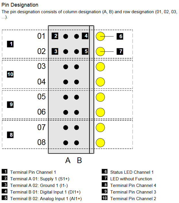
Pin allocation: 24 channels are divided into 3 groups, each group of pins including "power supply (Sx+), ground (Ix -), digital input (DIx+), analog input (AIx+)". Example (channels 1-8):
Pin Identification Function Description
A 01 S1+channels 1-8 power output
A 02 I1- Channel 1 Grounding
B 01 DI1+Channel 1 Digital Input
B 02 AI1+Channel 1 Analog Input
3. Software configuration
Tool adaptation:
System firmware<V7: configured using ELOP II Factory;
System firmware ≥ V7: Use SILworX (recommended, supports graphical interface);
Core configuration items:
Channel Type (AI/DI): Single channel independent setting Channel Used [BOOL] (1=enabled, 0=disabled);
Threshold configuration: Limit Value LOW/HIGH (DI mode: effective high and low level range; AI mode: under/over range threshold), Hysteresis LOW/HIGH (DI mode: switching threshold);
Power supply settings: Transmitter Voltage (8.2 V/26 V switching per group), Transmitter Used [BOOL] (whether to use module power supply).
Ordering and matching
1. Core components and spare parts
Component Name Model/Part Number Description
MI 24 01 module 98 2200115 24 channel safety input module (with normal coating, non optional uncoated version)
Two wire transmitter protection module 99 4703202 (H 7032) is compatible with two-wire transmitters and has SIL 3 safety protection
Three wire transmitter protection module 99 4703302 (H 7033) is compatible with three wire transmitters and has SIL 3 safety protection
The terminal plug does not have a clear part number for the module front board wiring terminal, and needs to be ordered separately
2. Documentation and technical support
Essential documents:
《HIMatrix System Manual Compact Systems》(HI 800 141 E);
《HIMatrix Safety Manual》(HI 800 023 E);
SILworX Online Help or ELOP II Factory Online Help;
Technical Support: HIMA Germany Headquarters (Phone+49 6202 709-0, Email) info@hima.com )Or regional agents (such as document provider SDS Automatyka).
Maintenance and lifecycle
Regular maintenance: Conduct precision calibration (analog input) and functional verification (safety circuit proof test) every 10 years;
Fault replacement: After a module failure, it needs to be replaced as a whole (cannot be repaired on site). When replacing, the system power supply needs to be disconnected, and the same model or HIMA certified replacement model should be used;
Scrap disposal: It is necessary to dispose of industrial electronic waste in accordance with the regulations. You can contact HIMA to sign a disposal agreement.
Key precautions
Channel configuration restrictions: 24 channels cannot be mixed into AI/DI mode and must be configured uniformly or grouped;
Power overload protection: Each group can provide a maximum of 200 mA of power. After overload, it will automatically restart within 30 seconds. If the overload persists, it will retry within 60 seconds. It is necessary to avoid connecting too many high-power devices to a single group;
Explosion proof scenario requirements: Zone 2 installation must meet EN 60079-15 enclosure protection (IP54+) and be labeled with "power-off operation only";
Software compatibility: The ELOP II Factory project and SILworX project are non editable, and compatibility needs to be confirmed before upgrading firmware.
- OMRON
- ABB
- General Electric
- EMERSON
- Honeywell
- HIMA
- ALSTOM
- Rolls-Royce
- MOTOROLA
- Rockwell
- Siemens
- Woodward
- YOKOGAWA
- FOXBORO
- KOLLMORGEN
- MOOG
- KB
- YAMAHA
- BENDER
- TEKTRONIX
- Westinghouse
- AMAT
- AB
- XYCOM
- Yaskawa
- B&R
- Schneider
- KONGSBERG
- NI
- WATLOW
- ProSoft
- SEW
- ADVANCED
- Reliance
- TRICONEX
- METSO
- MAN
- Advantest
- STUDER
- DANAHER MOTION
- Bently
- Galil
- EATON
- MOLEX
- DEIF
- B&W
- ZYGO
- Aerotech
- DANFOSS
- Beijer
- Moxa
- Rexroth
- Johnson
- WAGO
- TOSHIBA
- BMCM
- SMC
- HITACHI
- HIRSCHMANN
- Application field
- XP POWER
- CTI
- TRICON
- STOBER
- Thinklogical
- Horner Automation
- Meggitt
- Fanuc
- Baldor
- SHINKAWA
- Other Brands
- UniOP
- KUKA
- Iba
- Beckhoff
-
 OMRON B7AM-8B16 I/O Terminal Block
 -
 Fanuc A06B-6110-H026 Power Supply Module
 -
 Schneider TSXETG3021 Ethernet Gateway
 -
 OMRON CS1W-CLK21-V1 Controller Link Unit
 -
 NP1W6406T-Z704 PLC I/O Module
 -
 OMRON CJ1W-DA08C Analog Output Module
 -
 Yaskawa 3G3HV-A4022-CE AC Drive
 -
 OMRON NB7W-TW01B CP1L-EL20DR-D Power Panel
 -
 OMRON C500-NC103-E Position Control Unit
 -
 Steag Hamatech PLC DCS Servo Control System
 -
 Siemens 6SN1123-1AA00-0DA1 Power Supply Module
 -
 GE IC693CHS391H CPU & AD693CMM301A PLC Module
 -
 Siemens 6FC5303-0AF23-1AA1 PLC Control Panel
 -
 Square D CM4000T PowerLogic Circuit Monitor J1 F16
 -
 Siemens 6FX5002-5DG10-1BA0 MOTION-CONNECT 500 Cable
 -
 Schmersal SRB324ST 101195504 Safety Relay 24V
 -
 Mitsubishi 15050-PR02A PLC Circuit Board Module
 -
 OMRON CQM1-AD041 Analog Input PLC Module
 -
 Beckhoff EL5042 EtherCAT PLC Terminal Module
 -
 OMRON C200HW-MC402-E Motion Control Unit
 -
 C36TC0UA1100 Industrial Temperature Controller
 -
 NL8048BC24 12 Industrial Control LCD Module
 -
 OMRON R88D Servo Drive and Motor System
 -
 OMRON CS1W CLK21 V1 Controller Link Module
 -
 OMRON YASKAWA R7M A20030 S1 D Servo Motor
 -
 SIEMENS 6AV2128 3KB06 0AX1 Unified Comfort Panel
 -
 Schneider Electric METSEPM8240 PowerLogic Meter
 -
 Advanced AMCI 1PLC 1 31F Programmable Limit Switch
 -
 ABB PM582 ETH Programmable Logic Processor
 -
 SIEMENS 6FC5110 0CB01 0AA0 CPU Control Board
 -
 Schleicher P03GS13A CPU Module
 -
 Siemens 6SN1123-1AA00-0BA1 Power Module
 -
 Mitsubishi A1S61PN Power Supply Module
 -
 Yaskawa CPS-IONB DC Power Supply Module
 -
 Siemens 6ES7215-2BD00 CPU 215-2
 -
 Mitsubishi A2ACPU MELSEC PLC System Kit
 -
 ProSoft 3150-MCM Communication Module
 -
 Mitsubishi OSE104ET Incremental Encoder
 -
 OMRON CJ1W-AD081-V1 Analog Input Module
 -
 Broadcom BCM5464A1KRB Quad Port Ethernet IC
 -
 Modicon M221-24IO TM221C24 PLC 24 PNP Transistor
 -
 Allen-Bradley 1321-3R160-B Line Reactor 3R160B
 -
 Beckhoff CX1020-0012 Embedded PLC Module Specs
 -
 Turck BL20-PF-24VDC-D Power Feed Module Specs
 -
 Siemens 6SY7000-0AC37 Power Supply Module
 -
 Yaskawa SGDH-10DE-OY 1kW 400V Servo Drive Specs
 -
 Omron 3G3SV-BB015-E 1.5kW 220V VFD Specs
 -
 Uni-Pro CPU91-PLC J 23.020167X Processor Module
 -
 PASABAN MTC-3044 PLC Rack Power Supply 4835-A
 -
 XYCOM 3015T Operator Interface Panel BIN4.4.4
 -
 OMRON CJ1W-MD261 Mixed I/O Module
 -
 Omron NJ301-1100 PLC CPU eCat EIP Specs
 -
 Omron F500-C15-ETN Vision System PLC Module
 -
 Modicon M241-24IO TM/T2UK PLC with Ethernet
 -
 SIXNET YS-800-001 RTU PLC Module
 -
 BEMAC UST-202-D Interface Board 1307D V08B2
 -
 Yaskawa JANCD-MMOIC-02 Drive Circuit Board
 -
 ABB 3BSE005028R1 SDCS-COM-1 Comm Board
 -
 Omron 3G3MX2-A4110 A4150 Inverter Drives Specs
 -
 KEYENCE CA-E100 PLC Module
 -
 GE IC693ALG223-GB Analog Input Module Specs
 -
 ABB BAILEY IMMFP01 Multi Function Processor System
 -
 SIEMENS 6FC5372 0AA00 0AA1 NCU 7202 Controller
 -
Modicon TM241CE4 40I O Transistor Programmable Controller
-
 SIEMENS 6ES7 315 2EH13 0AB0 CPU 3152 PN DP
 -
 NORIS A1 91 PCB Card Rack Module System
 -
 SIEMENS 6ES7 313 5BE01 0AB0 Compact CPU
 -
 SCHNEIDER ELECTRIC S144B MICROLOGIC 60A Trip Unit
 -
 CNI PLC269 v3 Control Module Board Rev H
 -
ABB BAILEY IIMCP02 Processor Module
-
 OMRON NT20S ST121 EV3 Operator Interface Terminal
 -
 OMRON NS-CA001 Video Input Unit
 -
 GE Fanuc IC695CHS012 RX3i Backplane
 -
 Allen Bradley 2711E-K14C6 PanelView 1400e Terminal
 -
 Siemens Sinamics CCB 10000432.71 Power Cell
 -
 Siemens 6SL3210-1SE21-8UA0 Power Module PM340
 -
 Yaskawa CIMR-F7A20P4 AC Drive
 -
 Beckhoff EP1918-0002 EtherCAT Box I/O Module
 -
 OMRON CQM1-TC001 Temperature Control Module
 -
 GE Fanuc SGHA36AT0400 Industrial Contactor
 -
 OMRON NJ501-1500 PLC Machine Automation Controller
 -
 Mitsubishi MAZAK QX084 Power Supply MELDAS 500 CNC
 -
 B&R 0AC808.9 PLC Automation Module
 -
 OMRON CP1H-XA40DT1-D PLC Module
 -
 G&W Electric PLC15 5111 011 15kV Capnut Assembly
 -
 GE DS200SLCCG3AGH PCB Circuit Board
 -
 Siemens SINUMERIK 6FC3981-4FD PLC Extension
 -
 OMRON F300-DC I/O Image Processing Unit
 -
 FANUC A06B-0314-B002 AC Servo Motor
 -
 GC-S84 Programmable Controller Logic Module
 -
 PASABAN MONTELEC MTC3001-DC Drive Control PLC
 -
 Allen Bradley 100E460EJ11 Auxiliary Contactor
 -
 Bosch Rexroth 1070075337-101 Card Parameters
 -
 HMS Anybus AB7646-F Gateway Specifications
 -
 Bosch 062633-303401 CNC Servo PLC Card
 -
 TI 500-5023 Series PLC Power Supply
 -
 Siemens C98043-A7002-L1-12 Circuit Board
 -
 Omron E5CC-RX3A5M-000 Controller
 -
 CN-8032-L Profinet Network Adapter Module
 -
 Siemens 3TK2804-0BB4 Safety Relay Details
 -
 Toledo TTLM-2-1M I/O Load Module
 -
 NORIS A1-91 PLC Rack Board Specifications
 -
 Mitsubishi A3ACPUR21 MELSEC PLC CPU Module
 -
 Beckhoff EP7041‑3002 EtherCAT Box Digital Input Module
 -
 REER EOS2E 1053 EOS2R 1053 Safety Light Curtain
 -
 Mitsubishi Q80BD-J71BR11 MELSECNET/H Interface Board
 -
 Omron 3G3IV-B4220-EV2 VFD 400V 22kW
 -
 Allen-Bradley 96844671 1785-LT3 PLC-5/12 Processor Module
 -
 Pasaban MTC3001-DC Drive Control PLC Module
 -
 Omron CJ1M-CPU11 V4.0 PLC CPU Module
 -
 ABB CM579-PNIO B3 Communication Module
 -
 B&R X20 AI 4221 Analog Module
 -
 Siemens 6SY7000-0AC80 PLC Module
 -
 GE 531X300CCHAFM5 Control Card
 -
 AB 810-A15C Inverse Time Relay
 -
 WITTENSTEIN LP120X-MF2-20 Planetary Gear
 -
 Mitsubishi Kakoki E-01B-4130 PLC I/O Modules
 -
 ABB DSQC643 Safety Control Board
 -
 Siemens G26004-A2105-P100-2 PCB
 -
 OMRON F350-C10E Image Processing Unit
 -
 FUJI UG430H-TS1 HMI Touch Panel
 -
 Westronics CB100188-01 Rev F Board
 -
 Siemens 7MH4900-3AA01 Weighing Module
 -
 Gilbert & Nash Tracker 2000 Control Cabinet
 -
 OMRON CJ1M-CPU22 CPU Unit
 -
 OMRON F3SJ-E0625P25 Light Curtain
 -
 Siemens 3VA2340-5HL32-0AA0 Breaker
 -
 Mitsubishi Melsec A61P A2NCPU PLC System


