
How to install and maintain the Bently Nevada 3500 monitoring system rack?
Core advantage: Enhanced operator information (providing multi-dimensional data, Windows) ® Basic display software, better integration of factory control computers (multi protocol communication gateway, time synchronization data), reduced installation and maintenance costs (reduced wiring, backward compatibility, easy configuration), improved reliability (redundant power supply, TMR system), intrinsic safety options, multiple output interfaces (supporting multiple display and control systems).
Bently Nevada 3500 Monitoring System Rack Installation and Maintenance
Receiving and Processing Instructions
Receiving inspection
Visually inspect the system for any obvious transportation damage. If there is any damage, file a claim with the carrier and submit a copy to Bently Nevada, LLC.
Handling and storage precautions
The circuit board is susceptible to static damage and requires the use of a grounding strap (such as 3M Velostat) before operation ® No.2060) Grounding: Avoid using tools/materials that are prone to static electricity, such as ungrounded soldering irons and non-conductive plastics.
Transport and storage of circuit boards require the use of conductive bags or foil, and special attention should be paid to static electricity accumulation in dry weather (humidity<30%).
When the system loses power, it will lose its mechanical protection function; When operating correctly, the module can be plugged in and out while powered on (see Chapter 4 for details).
Basic Information
System Overview
The 3500 monitoring system is used to continuously monitor the status of rotating and reciprocating machinery (such as imbalance, misalignment, shaft cracks, bearing failures, etc.) to improve factory safety, product quality, equipment availability, and reduce operating costs.
Core advantage: Enhanced operator information (providing multi-dimensional data, Windows) ® Basic display software, better integration of factory control computers (multi protocol communication gateway, time synchronization data), reduced installation and maintenance costs (reduced wiring, backward compatibility, easy configuration), improved reliability (redundant power supply, TMR system), intrinsic safety options, multiple output interfaces (supporting multiple display and control systems).
General characteristics
Hot swappable module: When operated correctly, any module can be plugged in and out while the system is powered on, without affecting the operation of unrelated modules (plugging in and out of the power supply does not interrupt the system when dual power is available).
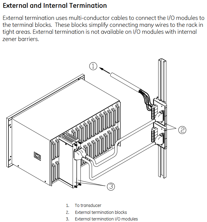
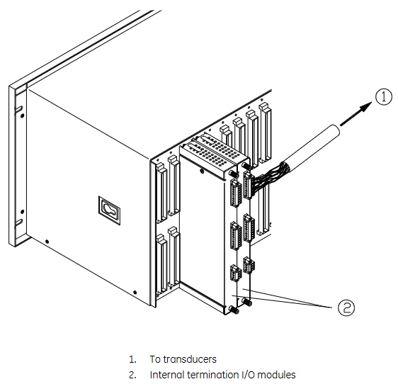
Internal and external terminals: External terminals are connected to I/O modules and terminal blocks through multi-core cables (suitable for narrow space areas); Internal terminals allow sensors to be directly connected to I/O modules (I/O modules with internal Zener barriers have no external terminals).
System components
Including a weatherproof enclosure (protecting the rack from moisture and dust), rack (full-size 19 inch/compact 12 inch Mini rack), power supply (half height module, supporting 1-2 redundant installations), Rack Interface Module (RIM, communicating with the host and other modules, maintaining event lists), communication gateway module (allowing external devices to access information), monitoring module (collecting sensor data), relay module (controlling relays based on channel status) Keyphasor ® Modules (supplying power to sensors and processing signals), display modules (supporting multiple display devices), grounding modules (providing low impedance grounding, used in conjunction with internal barrier I/O modules), etc.
Relays and Safety Systems
Standard rack relay options: independent relay (each monitoring module is equipped with more than one relay module), bus relay (multiple monitoring channels share a single relay), Triple Modular Redundancy (TMR) system (high reliability configuration, triple redundancy function, avoiding single point failure).
Intrinsic safety internal barrier system: suitable for hazardous environments, needs to be used in conjunction with grounding modules, has strict installation restrictions (such as prohibiting the use of bus sensors, requiring isolation of RS-232 connections, etc.), and has characteristics such as dual IS grounding and safe/hazardous area wiring separation.
Initial rack installation
General installation process
Refer to the installation checklist (confirm conditions such as power supply, space, ventilation, grounding, etc.);
Install weatherproof casing (if required);
Install the rack;
Set rack jumpers and switches;
Install external terminal blocks (if necessary);
Install modules;
Connect sensors, relays, and power wiring;
Complete the software configuration for rack installation.
Key installation details
Weather resistant enclosure: Meets NEMA 4 requirements, not compatible with display units; Attention should be paid to temperature derating (due to limited ventilation), panel cut size, conduit fittings (to avoid mixing power and signal wiring), and air purification options (to meet specific pressure and flow requirements).
Rack installation: Ensure ventilation (minimum gap of 50.4mm between top and bottom), support panel installation, rack installation (19 inch EIA cabinet), Bulkhead installation, etc. Different installation types have specific size and fixing requirements.
Intrinsic safety operation: Ensure that the grounding resistance is less than 1 Ω, use 4-10mm ² cables to connect to the factory's IS grounding, and use a single point grounding to avoid loops.
High electromagnetic noise/CE installation: The system rack, EMI shielding, and cables must be thoroughly grounded to shield all wiring out of the metal cabinet. CE installation must comply with EN61000.3.2 standard.
- ABB
- General Electric
- EMERSON
- Honeywell
- HIMA
- ALSTOM
- Rolls-Royce
- MOTOROLA
- Rockwell
- Siemens
- Woodward
- YOKOGAWA
- FOXBORO
- KOLLMORGEN
- MOOG
- KB
- YAMAHA
- BENDER
- TEKTRONIX
- Westinghouse
- AMAT
- AB
- XYCOM
- Yaskawa
- B&R
- Schneider
- Kongsberg
- NI
- WATLOW
- ProSoft
- SEW
- ADVANCED
- Reliance
- TRICONEX
- METSO
- MAN
- Advantest
- STUDER
- KONGSBERG
- DANAHER MOTION
- Bently
- Galil
- EATON
- MOLEX
- DEIF
- B&W
- ZYGO
- Aerotech
- DANFOSS
- Beijer
- Moxa
- Rexroth
- Johnson
- WAGO
- TOSHIBA
- BMCM
- SMC
- HITACHI
- HIRSCHMANN
- Application field
- XP POWER
- CTI
- TRICON
- STOBER
- Thinklogical
- Horner Automation
- Meggitt
- Fanuc
- Baldor
- SHINKAWA
- Other Brands
- UniOP
- KUKA
- Iba
-
 Schneider TM262L10MESE8T Logic Controller
 -
 8.4-inch NL8060BC21-06 Industrial Display
 -
 B&R X20CP0411 Compact CPU Control Unit
 -
 Schneider TSX P572634 M Modicon Premium CPU
 -
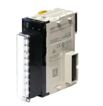
 Omron NX1P2-1140DT-BA Machine Controller
 -
 Siemens Ams-M35-K202 C8451-A20-A53-7
 -
 Omron FH-2050 Automation Controller
 -
 Omron CJ1W-NCF71 Position Control Unit
 -
 PILZ 777750 Safety Relay
 -
 BES58-P0CA0P-CD0H3PB0 Encoder 85409
 -
 Siemens 3VL5763-1DC36-0AA0 Molded Case Breaker
 -
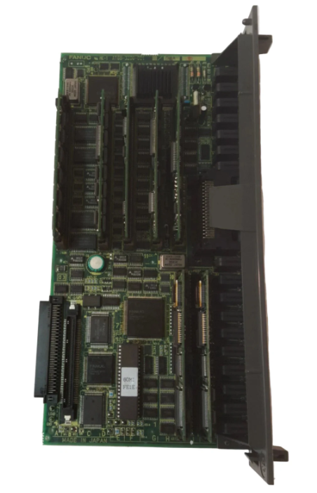 FANUC A16B-3200-0010 CPU Card
 -
 HINE DESIGN R94-1164 PLC Control Box 144760
 -
 Siemens PCU 50.5-C 6FC5210-0DF52-2AA0
 -
 PILZ PNOZ M0P Safety Relay 773110
 -
 Fanuc A20B-2101-0820 Control Circuit Board
 -
 Siemens 3SK1121-1AB40 Safety Relay
 -
 Pilz 772120 Safety Relay Expansion Module
 -
 Mitsubishi AX71 Input Module 16 Point
 -
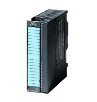 Siemens 6ES7350-1AH03-0AE0 S7-300 Extension
 -
 Fanuc A16B-3200-0010 CPU Card
 -
 Omron CJ1W-SCW22 Serial Communication Unit
 -
 Siemens 6SN1118-0DM21-0AA0 Control Module
 -
 Renishaw PHC10-3PLUS Controller Module
 -
 ABB AX521 1SAP250100R0001 Module
 -
 Omron NA5-9W001B-V1 PLC Module HMI
 -
 Infineon FF1000R17IE4 IGBT Power Module
 -
 Omron CJ1W-DA08C Analog Output Module
 -
 Omron CJ1G CPU45H CJ1H CPU66H CJ1G CPU43H CJ1W PA202
 -
 Omron CJ1W-DA041 Analog Output Module
 -
 Inductotherm 170-8031 PLC Control Module
 -
 Fuji Electric FPB56HR-A10 Programmable Logic Controller
 -
 Siemens 6SN1145-1BA01-0BA1 Infeed Regenerative Module
 -
 PILZ 777949 PSWZ X1P Safety Relay
 -
 Schneider 140NOM25200 DIO Head-end Adaptor
 -
 Siemens PXC5.E003 Controller BPZ
 -
 Schneider BMXEHC0800 Fast Counting Module 10kHz
 -
 Schneider BMXART0814 Isolated Thermocouple Inputs
 -
 Schneider BMXNOE0100 Ethernet Module 10 100 RJ45
 -
 LMX06-NS05 Sensor Industrial Proximity Switch
 -
 Siemens 6SN1145-1BB00-0FA1 Power Supply 156kW
 -
 Pro-face GP2500-LG41-24V HMI Graphic Panel
 -
Keyence CV-3001 Vision System CV3OO1
-
 Siemens 6GK5204-2BB10-2AA3 Ethernet Module
 -
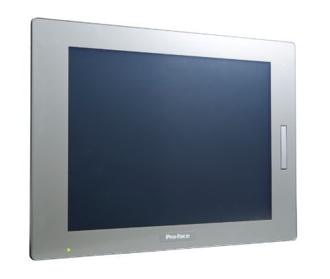 Pro-face PFXSP5500TPD 10.4in HMI LCD Display
 -
 Eu Automation 140DRA84000 Modicon Quantum Module
 -
 Siemens 6FC5210-0DF31-2AA0 Sinumerik PCU 50.3-C
 -
 Siemens 6SL3040-1NC00-0AA0 Sinumerik NX10.3 Extension
 -
 Gould AS-884A-111 Modicon 884 Controller
 -
 Allen Bradley 1336E-BRF30-AA-EN-HA2-L5 Impact Drive
 -
 Siemens 6FC5110-0BB02-0AA1 Sinumerik 840D CPU Card
 -
 Pilz 773500 PNOZmulti Expansion Module
 -
 Siemens 6ES7350-1AH03-0AE0 S7-300 Counter Module
 -
 Siemens 6FC5110-0DB01-0AA1 Sinumerik 840D Card
 -
 HPM 1D703-0040 Command 9000 VGA Console Board
 -
 OMRON CJ1W-PTS52 Temperature Unit
 -
 Sacs Technique PCD4.M12 Module
 -
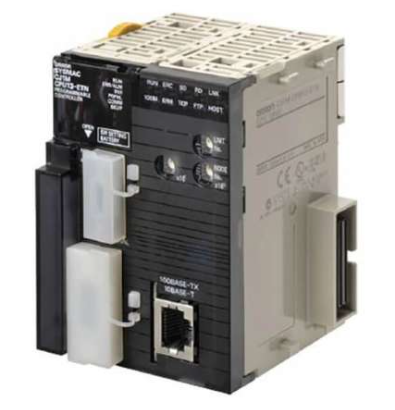 OMRON CJ1M-CPU11-ETN Ethernet CPU
 -
 OMRON CJ1M-CPU23 PLC CPU Unit
 -
 OMRON NX-SID800 Safety Input Unit
 -
 GE Fanuc Series 90-30 PLC
 -
 OMRON CJ1W-NCF71 Position Control
 -
 OMRON CJ1W-AD081-V1 Analog Input
 -
 OMRON FZ-S2M Vision Camera
 -
 OMRON R88D-UEP20V Servo Driver
 -
 OMRON F500-C10-ETN Vision Controller
 -
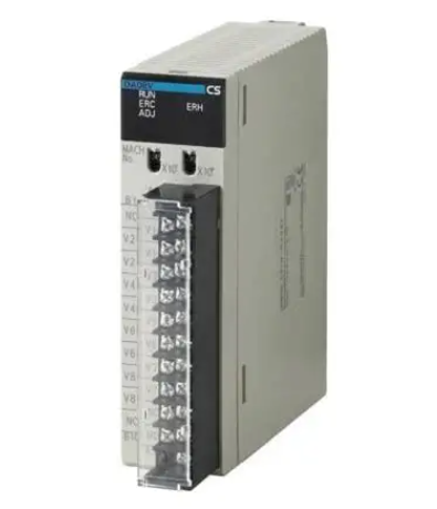 OMRON CS1W-DA041 Analog Output Module
 -
 PRO-FACE GP577R-TC41-24VP HMI Panel
 -
 TRUTZSCHLER RAK 1 492-58.430.000 PLC Module
 -
 OMRON NX-OD5256 Output Module
 -
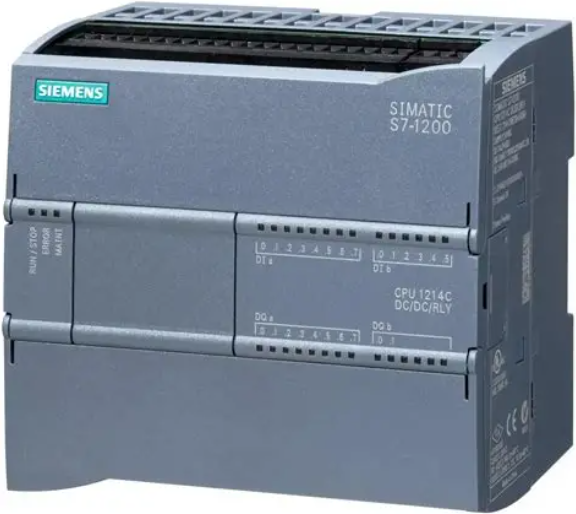 Siemens 6AG1214-1AG40-4XB0 PLC
 -
 OMRON CJ1W-AD081-V1 Analog Unit
 -
 OMRON C500-CPU11-E PLC CPU
 -
 OMRON NX-ECC201 EtherCAT Coupler
 -
 OMRON F300-A20S Camera Interface
 -
 Mitsubishi 80173-109-01 PLC Module
 -
 Fanuc A16B-2200-0141 PCB Board
 -
 Lenze EPL10200 PLC Module
 -
 OMRON CJ1M-CPU13 PLC CPU Unit
 -
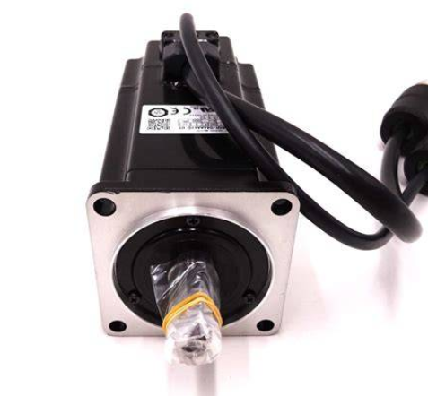 Yaskawa SGMPH-04AAA61D-OY Motor
 -
 OMRON NX-SOD400 Safety Output
 -
 Control Techniques V1800 Flux Vector Drive
 -
 Yaskawa SGDH-04AE-OY Servo Drive
 -
 OMRON NT-DRT21 DeviceNet Interface
 -
 OMRON C500-RM001-V1 Remote I/O Master
 -
 OMRON C500-AD006 Analog Input Module
 -
 OMRON 3G3MV-A4055 Inverter Drive
 -
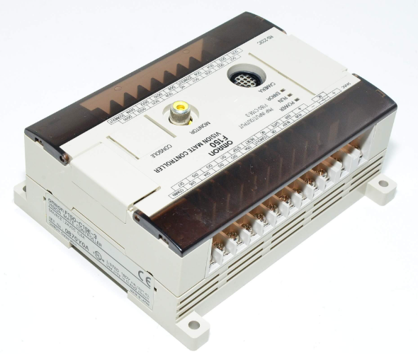 OMRON F150-C15E-3 Vision Mate Controller
 -
 OMRON CS1G-CPU44H PLC CPU
 -
 GE Fanuc DS6800CCIE1E1D CPU Module
 -
 Omron CP1L-M30DR-A PLC CP1W-CIF01 CPU Unit
 -
 Heraeus 585923 2M130 M8 Electrode Assembly Sensor
 -
 Omron C40P-EDT1-D C Series PLC Controller
 -
 Yaskawa SGMGH-09DCA6F-OY Servo Motor SGDH Driver
 -
 Datalogic SG-BWS-T4-MT Safety Control Unit Category 4
 -
 Pro-face PFXLM4301TADDC HMI Controller LT-4301M
 -
 Mitsubishi FX1N-60MR-DS PLC Main Unit 60 I/O
 -
 Omron NJ501-1320 Sysmac Database Connection CPU
 -
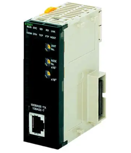
 Omron CJ1W-ETN21 Ethernet Unit CJ Series Module
 -
 Siemens 6ES7517-3AP00-0AB0 CPU 1517-3 PN/DP
 -
 Pasaban MTC-3052 Fast I/O PLC Module
 -
 Mitsubishi FX3U-128MR/ES-A PLC
 -
 OMRON CS1W-CLK21 Controller Link Unit
 -
 Yokogawa ADV151-E63 Digital Input Module
 -
 Allen Bradley MPL-B680B-M-X227 Motor
 -
 OMRON CJ1W-NC413 4-Axis Position Unit
 -
 Yaskawa SGMGH-30DCA6H-OY Servo Motor
 -
 Bosch 1070075337-101 Output Card
 -
 OMRON CQM1-CPU45-EV1 PLC CPU Unit
 -
 Siemens 6SE7090-0XX84-0AG1 CU3 Control Module
 -
 OMRON CQM1-TC101 Temperature Control Module
 -
 MOOG OEM-1030-422 Wind Energy PLC Controller
 -
 OMRON ZFX-C15 Vision Sensor
 -
 Square D 8702SCO2V02 Reversing Contactor
 -
 OMRON C20-LK201-EV1 PLC Link Adapter
 -
 OMRON NB7W-TW01B HMI PLC
 -
 Siemens 7ME6920-1AA10-1AA0 Flow Transmitter
 -
 Allen Bradley 1791-8BR Block I/O Module
 -
 OMRON CQM1-AD041 Analog Input Module
 -
 OMRON CJ1M-CPU21 PLC Module
 -
 Omron Z500-MC10E-001 Laser Profile Controller
 -
 Omron NA5-7W001B-V1 NA Series Programmable Terminal HMI
 -
 Allen-Bradley 1606-XLS960EE Power Supply 960W 24VDC
 -
 GE DS3800NEPB1F1E Power Excitation Board Mark IV
 -
 Yaskawa SGDH-04AE-OY Sigma-II Servo Drive 400W
 -
 Allen-Bradley 2711P-RBT7 PanelView Plus 7 Bezel
 -
 CCS PD3-3024-3-EI Digital Control Unit 3 Channel
 -
 Yaskawa CPU301 MP3300 Controller JAPMC-CP3301-2-E


