
YAMAHA RCX40 4-axis robot controller
Warning: Violation may result in serious injury or death to personnel, involving critical scenarios such as emergency stop, power operation, and use in explosive environments.
CAUTION: Violation may result in minor injuries to personnel or equipment damage, involving scenarios such as cable layout, environmental adaptation, and component operation.
NOTE: Clarify the key points of operation and assist in the correct use of equipment.
2. Key safety requirements
The system design should include physical interlock circuits, and the emergency stop terminals should be configured correctly.
Control cables and power cables should maintain a minimum distance of 100mm to avoid electromagnetic interference.
Before installation and wiring, all power phases must be cut off to prevent electric shock; After wiring, the terminal cover needs to be installed before powering on.
Only personnel who have received safety and operation training are allowed to operate the robot, and personnel are prohibited from entering the movement range during operation.
The controller is not designed to be explosion-proof and is prohibited from being used in environments with flammable gases, gasoline, or solvents.
Power off and wait for at least 30 minutes before maintenance to avoid damage from high temperature or high pressure components.
YAMAHA RCX40 4-axis robot controller
Core Security Standards
1. Definition of Security Level
Warning: Violation may result in serious injury or death to personnel, involving critical scenarios such as emergency stop, power operation, and use in explosive environments.
CAUTION: Violation may result in minor injuries to personnel or equipment damage, involving scenarios such as cable layout, environmental adaptation, and component operation.
NOTE: Clarify the key points of operation and assist in the correct use of equipment.
2. Key safety requirements
The system design should include physical interlock circuits, and the emergency stop terminals should be configured correctly.
Control cables and power cables should maintain a minimum distance of 100mm to avoid electromagnetic interference.
Before installation and wiring, all power phases must be cut off to prevent electric shock; After wiring, the terminal cover needs to be installed before powering on.
Only personnel who have received safety and operation training are allowed to operate the robot, and personnel are prohibited from entering the movement range during operation.
The controller is not designed to be explosion-proof and is prohibited from being used in environments with flammable gases, gasoline, or solvents.
Power off and wait for at least 30 minutes before maintenance to avoid damage from high temperature or high pressure components.
System Overview and Core Functions
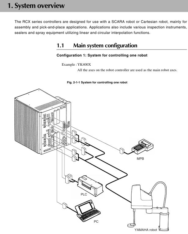
1. System configuration
Supports two core configurations: single robot control and single robot+auxiliary axis control (up to 4 axes).
The axis definition includes the main robot axis, main auxiliary axis, sub robot axis, and sub auxiliary axis, which can be switched through the MPB programming unit.
Optional devices include MPB programmer, expansion I/O board (up to 4 pieces), and regeneration unit, adapted to different system requirements.
2. Core functional highlights
Multi tasking function: Up to 8 tasks can be run simultaneously, supporting priority settings to improve system efficiency.
Robot Language: Adopting a high-level language similar to BASIC, in compliance with the industrial robot programming standard SLIM, supporting compilation and execution, and efficient programming.
Motion control: Supports Arch motion (freely set pick and place paths), 3D CP control (linear/arc interpolation motion), and reduces cycle time.
Easy maintenance: Software servo control achieves unit standardization, compatible with most YAMAHA robot models, simplifying maintenance and adjustment.
Compliance: Compliant with the Machinery Directive, Low Voltage Directive, and EMC Directive, supporting SAFE mode operation.
Installation and wiring specifications
1. Installation requirements
Environmental conditions: operating temperature of 0-40 ℃, storage temperature of -10-65 ℃, humidity of 35% -85% (no condensation), avoiding vibration, conductive dust, and corrosive gas environment.
Installation space: Reserve at least 50mm gap on the top and sides, and at least 30mm gap on the back to ensure heat dissipation and ventilation.
Installation method: Supports four installation methods: rubber foot pad installation, front and rear panel L-shaped bracket installation, and side L-shaped bracket installation.
2. Key wiring points
Power connection: Supports AC200-230V single-phase input, requires correct connection of live wire (L), neutral wire (N), and ground wire, and voltage fluctuation should be controlled within ± 10%.
Cable layout: Robot cables need to be separated from power cables to avoid entanglement; When wiring, designated tools must be used to ensure the quality of crimping and welding.
Absolute battery connection: The battery is not connected when it leaves the factory. After installation, the battery needs to be connected first and then the robot cable needs to be connected. The battery needs to be replaced regularly (about 1.5 years).
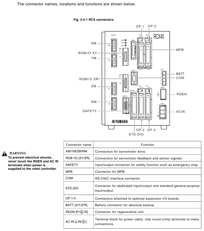
Emergency stop circuit: It is necessary to correctly connect the emergency stop signal through the SAFETY interface to ensure that the power is quickly cut off when triggered.
Operation mode and core operation
1. Main operating modes
Service mode: Only available in SAFE mode, used for maintenance within safety fences, limiting operating speed (≤ 3% maximum speed), and prohibiting automatic mode operation.
AUTO mode: executes robot programs, supports program reset, task switching, speed adjustment, breakpoint setting, and other functions.
Program mode: Create, edit, and manage robot programs, supporting operations such as program copying, deletion, renaming, and compilation.
MANUAL mode: Manually move the robot, perform point teaching, support absolute reset, coordinate setting, hand definition editing, etc.
SYSTEM mode: Configure system parameters, communication parameters, option functions, support data initialization, backup, and diagnosis.
UTILITY mode: handles auxiliary functions such as emergency stop cancellation, motor power switch, and execution level adjustment.
2. Key operational procedures
Absolute reset: When the origin is lost, it needs to be executed and supports single axis or full axis reset. Before resetting, ensure that the axis is in a safe position.
Program execution: Start the program in AUTO mode and debug it through STEP, SKIP, and NEXT.
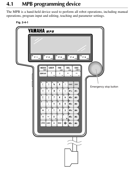
Point teaching: In MANUAL mode, use the Jog key to move the robot to the target position and execute the TEACH command to save point data.
Data backup: Backup programs, parameters, point data, etc. to internal flash ROM through SYSTEM mode to avoid data loss.
I/O interface and communication
1. Standard I/O interface
It includes 10 dedicated inputs, 11 dedicated outputs, 16 universal inputs, and 8 universal outputs, and supports NPN/PNP specifications.
Specialized inputs include signals such as servo ON, program start, automatic mode switching, emergency stop, etc; Dedicated outputs include signals such as CPU status, servo status, alarm, program running status, etc.
2. Communication interface
Supports RS-232C interface, can connect to upper computer for data communication, and supports online command execution.
Communication parameters can be configured: baud rate (4800-57600bps), data bits (7/8 bits), stop bits (1/2 bits), parity bits (NONE/ODD/EVENT), etc.
Maintenance and troubleshooting
1. Key points of daily maintenance
Regularly check the absolute battery voltage (normal 3.50-4.3V), and if it is lower than 3.5V, it needs to be charged or replaced.
Regularly backup programs and parameters to avoid data loss caused by hardware failures.
Check if the cable connection is secure to avoid loosening and causing malfunctions.
Clean the controller's cooling fan and fins to ensure good heat dissipation.
2. Fault handling
View error messages through the MPB screen and refer to the "Troubleshooting" section to locate the problem.
Common errors include loss of origin, low battery voltage, program syntax errors, abnormal I/O signals, etc., which require targeted handling.
Malfunctions that cannot be resolved on their own require contacting YAMAHA authorized dealers or technical support.
- OMRON
- ABB
- General Electric
- EMERSON
- Honeywell
- HIMA
- ALSTOM
- Rolls-Royce
- MOTOROLA
- Rockwell
- Siemens
- Woodward
- YOKOGAWA
- FOXBORO
- KOLLMORGEN
- MOOG
- KB
- YAMAHA
- BENDER
- TEKTRONIX
- Westinghouse
- AMAT
- AB
- XYCOM
- Yaskawa
- B&R
- Schneider
- KONGSBERG
- NI
- WATLOW
- ProSoft
- SEW
- ADVANCED
- Reliance
- TRICONEX
- METSO
- MAN
- Advantest
- STUDER
- DANAHER MOTION
- Bently
- Galil
- EATON
- MOLEX
- DEIF
- B&W
- ZYGO
- Aerotech
- DANFOSS
- Beijer
- Moxa
- Rexroth
- Johnson
- WAGO
- TOSHIBA
- BMCM
- SMC
- HITACHI
- HIRSCHMANN
- Application field
- XP POWER
- CTI
- TRICON
- STOBER
- Thinklogical
- Horner Automation
- Meggitt
- Fanuc
- Baldor
- SHINKAWA
- Other Brands
- UniOP
- KUKA
- Iba
- Beckhoff
-
 OMRON C60H C6DR DE V1 Sysmac PLC
 -
 MITSUBISHI ELECTRIC A2ACPU21 S1 CPU Module
 -
 ABB BAILEY INNPM12 Network Process Module
 -
 HONEYWELL 620 0073C IPC PLC Module
 -
 Mitsubishi 15050 PR02B PLC Circuit Board
 -
 SIEMENS 6SY7000 0AC37 Drive Control Module
 -
 OMRON TJ2 ECT16 Traxial EtherCAT Controller
 -
 GE Fanuc IC698PSD300D Power Supply Module
 -
 Texas Instruments Series 505 16 Position Base
 -
 OMRON YASKAWA SGDH 10DE OY Servo Drive
 -
 Allen‑Bradley 440G-MT Safety Interlock Switch Specs
 -
 Rubycon PD27A 24V 8A Power Supply Module
 -
 SK-H1-GDB1-F11D PLC Gate Driver Board Kit
 -
 VIPA 441-4UA14 451-4UA14 PLC Module Rack
 -
 Mitsubishi FX5U-80MT ESS PLC Controller Specs
 -
 Mitsubishi Q64TCRTN Temperature PLC Module
 -
 GE 1C31170G Rev10 PLC Circuit Board Module
 -
 Schneider TWDLMDA40DTK PLC Controller Module
 -
 Omron FQM1-MMA22 Motion Control Module Specs
 -
 OMRON CJ1W-NCF71 Position Control Unit Specs
 -
 Schneider TSXETY4103 Ethernet Module
 -
 Mitsubishi Q12PHCPU Process CPU
 -
 Yaskawa 3G3HV-A4022-CE AC Drive
 -
 Cincinnati Milacron 3-533-0669G Temperature Control Board
 -
 Allen Bradley 20AC030A3AYNANC0 PowerFlex 70 Drive
 -
 Siemens 6ES7314-6BG03-0AB0 CPU 314C-2 DP
 -
 Carrier 17EX54007903 PLC Module
 -
 OMRON CS1W-V600C12 ID Controller Module
 -
 Honeywell 51402755-100 PCB Card
 -
 Heidenhain ECN 113 Rotary Encoder
 -
 OMRON B7AM-8B16 I/O Terminal Block
 -
 Fanuc A06B-6110-H026 Power Supply Module
 -
 Schneider TSXETG3021 Ethernet Gateway
 -
 OMRON CS1W-CLK21-V1 Controller Link Unit
 -
 NP1W6406T-Z704 PLC I/O Module
 -
 OMRON CJ1W-DA08C Analog Output Module
 -
 Yaskawa 3G3HV-A4022-CE AC Drive
 -
 OMRON NB7W-TW01B CP1L-EL20DR-D Power Panel
 -
 OMRON C500-NC103-E Position Control Unit
 -
 Steag Hamatech PLC DCS Servo Control System
 -
 Siemens 6SN1123-1AA00-0DA1 Power Supply Module
 -
 GE IC693CHS391H CPU & AD693CMM301A PLC Module
 -
 Siemens 6FC5303-0AF23-1AA1 PLC Control Panel
 -
 Square D CM4000T PowerLogic Circuit Monitor J1 F16
 -
 Siemens 6FX5002-5DG10-1BA0 MOTION-CONNECT 500 Cable
 -
 Schmersal SRB324ST 101195504 Safety Relay 24V
 -
 Mitsubishi 15050-PR02A PLC Circuit Board Module
 -
 OMRON CQM1-AD041 Analog Input PLC Module
 -
 Beckhoff EL5042 EtherCAT PLC Terminal Module
 -
 OMRON C200HW-MC402-E Motion Control Unit
 -
 C36TC0UA1100 Industrial Temperature Controller
 -
 NL8048BC24 12 Industrial Control LCD Module
 -
 OMRON R88D Servo Drive and Motor System
 -
 OMRON CS1W CLK21 V1 Controller Link Module
 -
 OMRON YASKAWA R7M A20030 S1 D Servo Motor
 -
 SIEMENS 6AV2128 3KB06 0AX1 Unified Comfort Panel
 -
 Schneider Electric METSEPM8240 PowerLogic Meter
 -
 Advanced AMCI 1PLC 1 31F Programmable Limit Switch
 -
 ABB PM582 ETH Programmable Logic Processor
 -
 SIEMENS 6FC5110 0CB01 0AA0 CPU Control Board
 -
 Schleicher P03GS13A CPU Module
 -
 Siemens 6SN1123-1AA00-0BA1 Power Module
 -
 Mitsubishi A1S61PN Power Supply Module
 -
 Yaskawa CPS-IONB DC Power Supply Module
 -
 Siemens 6ES7215-2BD00 CPU 215-2
 -
 Mitsubishi A2ACPU MELSEC PLC System Kit
 -
 ProSoft 3150-MCM Communication Module
 -
 Mitsubishi OSE104ET Incremental Encoder
 -
 OMRON CJ1W-AD081-V1 Analog Input Module
 -
 Broadcom BCM5464A1KRB Quad Port Ethernet IC
 -
 Modicon M221-24IO TM221C24 PLC 24 PNP Transistor
 -
 Allen-Bradley 1321-3R160-B Line Reactor 3R160B
 -
 Beckhoff CX1020-0012 Embedded PLC Module Specs
 -
 Turck BL20-PF-24VDC-D Power Feed Module Specs
 -
 Siemens 6SY7000-0AC37 Power Supply Module
 -
 Yaskawa SGDH-10DE-OY 1kW 400V Servo Drive Specs
 -
 Omron 3G3SV-BB015-E 1.5kW 220V VFD Specs
 -
 Uni-Pro CPU91-PLC J 23.020167X Processor Module
 -
 PASABAN MTC-3044 PLC Rack Power Supply 4835-A
 -
 XYCOM 3015T Operator Interface Panel BIN4.4.4
 -
 OMRON CJ1W-MD261 Mixed I/O Module
 -
 Omron NJ301-1100 PLC CPU eCat EIP Specs
 -
 Omron F500-C15-ETN Vision System PLC Module
 -
 Modicon M241-24IO TM/T2UK PLC with Ethernet
 -
 SIXNET YS-800-001 RTU PLC Module
 -
 BEMAC UST-202-D Interface Board 1307D V08B2
 -
 Yaskawa JANCD-MMOIC-02 Drive Circuit Board
 -
 ABB 3BSE005028R1 SDCS-COM-1 Comm Board
 -
 Omron 3G3MX2-A4110 A4150 Inverter Drives Specs
 -
 KEYENCE CA-E100 PLC Module
 -
 GE IC693ALG223-GB Analog Input Module Specs
 -
 ABB BAILEY IMMFP01 Multi Function Processor System
 -
 SIEMENS 6FC5372 0AA00 0AA1 NCU 7202 Controller
 -
Modicon TM241CE4 40I O Transistor Programmable Controller
-
 SIEMENS 6ES7 315 2EH13 0AB0 CPU 3152 PN DP
 -
 NORIS A1 91 PCB Card Rack Module System
 -
 SIEMENS 6ES7 313 5BE01 0AB0 Compact CPU
 -
 SCHNEIDER ELECTRIC S144B MICROLOGIC 60A Trip Unit
 -
 CNI PLC269 v3 Control Module Board Rev H
 -
ABB BAILEY IIMCP02 Processor Module
-
 OMRON NT20S ST121 EV3 Operator Interface Terminal
 -
 OMRON NS-CA001 Video Input Unit
 -
 GE Fanuc IC695CHS012 RX3i Backplane
 -
 Allen Bradley 2711E-K14C6 PanelView 1400e Terminal
 -
 Siemens Sinamics CCB 10000432.71 Power Cell
 -
 Siemens 6SL3210-1SE21-8UA0 Power Module PM340
 -
 Yaskawa CIMR-F7A20P4 AC Drive
 -
 Beckhoff EP1918-0002 EtherCAT Box I/O Module
 -
 OMRON CQM1-TC001 Temperature Control Module
 -
 GE Fanuc SGHA36AT0400 Industrial Contactor
 -
 OMRON NJ501-1500 PLC Machine Automation Controller
 -
 Mitsubishi MAZAK QX084 Power Supply MELDAS 500 CNC
 -
 B&R 0AC808.9 PLC Automation Module
 -
 OMRON CP1H-XA40DT1-D PLC Module
 -
 G&W Electric PLC15 5111 011 15kV Capnut Assembly
 -
 GE DS200SLCCG3AGH PCB Circuit Board
 -
 Siemens SINUMERIK 6FC3981-4FD PLC Extension
 -
 OMRON F300-DC I/O Image Processing Unit
 -
 FANUC A06B-0314-B002 AC Servo Motor
 -
 GC-S84 Programmable Controller Logic Module
 -
 PASABAN MONTELEC MTC3001-DC Drive Control PLC
 -
 Allen Bradley 100E460EJ11 Auxiliary Contactor
 -
 Bosch Rexroth 1070075337-101 Card Parameters
 -
 HMS Anybus AB7646-F Gateway Specifications
 -
 Bosch 062633-303401 CNC Servo PLC Card
 -
 TI 500-5023 Series PLC Power Supply
 -
 Siemens C98043-A7002-L1-12 Circuit Board
 -
 Omron E5CC-RX3A5M-000 Controller


