
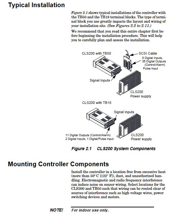
Watlow CLS200 series controller
Watlow CLS200 series controller
Product Overview and Core Features
1. Product positioning and circuit configuration
The CLS200 series controller is an industrial grade multi loop control device that provides 4 (CLS204), 8 (CLS208), or 16 (CLS216) completely independent control loops. It can be used as an independent controller (operated through a 2-line 16 character display screen and touch keyboard) or as a core component of a computer monitoring data acquisition and control system, supporting local or remote control through EIA/TIA-232 or EIA/TIA-485 serial communication interfaces.
2. Core functional features
Multi type sensor compatibility: directly connect multiple thermocouples (J, K, T, S, R, B, E types) without hardware modification, with reference compensation, linearization, measurement offset calibration, disconnection/short circuit/reverse connection detection functions, supporting Fahrenheit/Celsius display; Support 3-wire 100 Ω platinum resistance RTD (0.00385 curve), calibration resistors need to be configured for CLS204/CLS208; Automatic calibration of linear analog input (requires installation of calibration resistors), input two points to automatically calibrate according to user units.
Flexible output control: Each circuit includes dual outputs for heating and cooling, with independent configuration of output parameters; Supports multiple control and output modes, with control outputs set to ON/OFF, TP, DZC, and SDAC modes. Each circuit can have up to 2 outputs set to ON/OFF, P, PI, or PID control, and supports reverse/forward actions.
Alarm and Monitoring: Supports high/low process alarm and high/low deviation alarm. Each loop alarm can independently activate digital output or group activate output; The global alarm output is activated upon any alarm trigger and needs to be manually confirmed before being turned off; The CPU watchdog timer output can monitor system faults, keep the relay closed during controller operation, and trigger notifications when the microprocessor shuts down.
Communication and Storage: Supports Modbus RTU protocol, connects PLC, operation interface terminal, and third-party software through EIA/TIA-232/485 interface; The memory can store up to 8 tasks, which can be called locally or remotely through numerical input. Each task includes operating conditions such as set values and alarms.
Other practical functions: support non-linear output curve selection; The self-tuning function can quickly optimize PID parameters; Pulse counter input (up to 2000Hz) can accurately control motor or belt speed; Low power shutdown function, automatically shuts down and all outputs when the input voltage is below the safe value detected 🔶 1-163, 1-164, 1-165, 1-166 🔷。
Installation Guide
1. Preparation and safety requirements before installation
Environmental requirements: The controller should be installed in a location without excessive temperature (not exceeding 50 ℃/122 ℉), low dust, and unauthorized operation, to avoid electromagnetic and radio frequency interference. Sensor wiring should be kept away from high-voltage lines, power switch equipment, and motors.
Safety warning: Cut off the power supply throughout the entire process before installation to prevent electric shock; The controller may malfunction to 0% or 100% power output state, requiring the installation of independent external safety shutdown devices (such as FM certified high/low process limit controllers and mechanical contactors), and the safety devices must be independent of the process control equipment. If the malfunction may result in death or injury, FM certified safety devices must be used.
Tool preparation: It is recommended to use a 1/8-DIN rectangular punch (such as Greenlee 600-68), curved saw and metal file (stainless steel/thick panel), nibbler and metal file (aluminum/light panel), as well as a cross screwdriver, 1/8 inch (3mm) straight screwdriver (for wiring), and multimeter.
2. Installation steps of core components
(1) Controller installation
Panel opening: A hole of 1.80 inches (46mm) x 3.63 inches (92mm) (tolerance ± 0.02 inches/1mm) needs to be opened on the panel, and the panel thickness should not exceed 0.2 inches (5mm).
Installation process: First, remove the bracket and collar of the processor module, and slide the module into the panel cut; Insert the installation collar onto the back of the module (with the screw groove facing back), loosen the screws of the installation bracket, insert the bracket into the installation groove (with the screw head facing back), tighten and fix it laterally; Ensure that the casing is installed in place and tighten the screws to secure the bracket against the collar.
Space requirements: The controller can extend up to 7.0 inches (178mm) behind the panel, and the screw bracket can extend up and down by 0.5 inches (13mm) each; If using a straight SCSI cable, an additional 1.6 inches (41mm) should be reserved behind the terminal board; If using a right angle SCSI cable, an additional 0.6 inches (15mm) need to be reserved.
(2) Installation of TB50 terminal board
TB50 is a screw terminal interface used to connect relays, encoders, and discrete I/O devices. It supports 18 AWG (0.75mm ²) wires and is connected to the controller through a 50 pin SCSI cable. There are two installation methods:
- OMRON
- ABB
- General Electric
- EMERSON
- Honeywell
- HIMA
- ALSTOM
- Rolls-Royce
- MOTOROLA
- Rockwell
- Siemens
- Woodward
- YOKOGAWA
- FOXBORO
- KOLLMORGEN
- MOOG
- KB
- YAMAHA
- BENDER
- TEKTRONIX
- Westinghouse
- AMAT
- AB
- XYCOM
- Yaskawa
- B&R
- Schneider
- KONGSBERG
- NI
- WATLOW
- ProSoft
- SEW
- ADVANCED
- Reliance
- TRICONEX
- METSO
- MAN
- Advantest
- STUDER
- DANAHER MOTION
- Bently
- Galil
- EATON
- MOLEX
- DEIF
- B&W
- ZYGO
- Aerotech
- DANFOSS
- Beijer
- Moxa
- Rexroth
- Johnson
- WAGO
- TOSHIBA
- BMCM
- SMC
- HITACHI
- HIRSCHMANN
- Application field
- XP POWER
- CTI
- TRICON
- STOBER
- Thinklogical
- Horner Automation
- Meggitt
- Fanuc
- Baldor
- SHINKAWA
- Other Brands
- UniOP
- KUKA
- Iba
- Beckhoff
-
 Basler D90 96801 100 PCB Card
 -
 Basler XR2002F Voltage Regulator (110 VAC, 48-480 Hz)
 -
 Basler SR8A-2B14B3A Regulator
 -
 Basler 9561500100 Module
 -
 Basler DECS-400 BE1-11 System
 -
 Basler DECS-100-B15 Excitation Control
 -
 Basler SCP 210 Frequency Controller
 -
 Basler SR4A-2B15B3A Static Voltage Regulator
 -
 Basler BE1-32R Power Relay
 -
 Basler PIA2400-17GM Power Interface Adapter
 -
 Basler MVC 232 Manual Voltage Control Module
 -
 Basler SSR 32-12 Static Voltage Regulator
 -
 Basler 5MW AVR Generator Voltage Regulator
 -
 Basler VR63-4B Voltage Regulator
 -
 Basler DECS-100-A05 AVR for Engine Generator
 -
 Basler DECS-100-B15 Automatic Voltage Regulator
 -
 Basler BE1-32R Directional Power Relay
 -
 Basler BE1-87B Differential Relay
 -
 Basler UFOV 260A Protective Module
 -
 Basler 9-2614-02-100 PCB Rev M
 -
Basler DECS-100-B15 Digital AVR
-
 Basler 9284900103 PS DECS-400N
 -
 Basler D4N3H1U Intertie Protection
 -
 Basler DECS-100-B15 A15 AVR
 -
 Basler KR4F Voltage Regulator
 -
 Basler BE26434 T14 Transformer
 -
 Basler SR8A-2B15B3A Regulator
 -
 Westinghouse 774B472A12 AR Relay
 -
Basler DECS-100-B15 AVR
-
Basler XR2002F Regulator 110V
-
Basler SR125-E Static Regulator
-
 Basler SSR 125-12 Regulator
 -
 Basler MOC2599 Motor Pot
 -
 Basler BE1-DFPR Feeder Relay
 -
 Basler CBS 305 Current Boost
 -
 Basler BE1-25 AutoSync
 -
 Basler MVC 300 Voltage Control
 -
 Basler BE3-25A AutoSync
 -
 Basler KR7FF Static Regulator
 -
 Basler 90-49000-100 Regulator
 -
 Basler 880 kVA Dry Type Transformer Specs
 -
 Basler Electric BE1-25 Sync-Check Relay Specs
 -
 Basler SSR 125-12 Voltage Regulator Specs
 -
 Basler Electric BE1-851 Overcurrent Relay Review
 -
Basler Electric 149D930G02 Control Sub-Assembly
-
 Basler Electric BE1-81O/UT Frequency Relay Specs
 -
 Basler Electric BE1-51/27C Overcurrent Relay
 -
 Basler Electric 149D956G02 Industrial Component
 -
Basler Electric BE1-51A Overcurrent Relay Specs
-
 Basler Electric BE1-40Q Loss of Excitation Relay
 -
 Basler DECS-200 Excitation Control System
 -
 Basler DECS-200 Voltage Regulator 56-277V AC / 125V DC
 -
Basler BE1-87T Transformer Differential Relay
-
 Basler RDP-110-S1 Protection Relay
 -
 Basler BE1-700V Digital Protective Relay
 -
 Basler BE1-951 Overcurrent Protection System
 -
 Basler DECS-300 Digital Excitation Control
 -
 Basler DECS-200 Digital Excitation Control
 -
 Basler DECS-200-1C Excitation Control System
 -
Basler DECS-200-1L Digital Excitation Control
-
 Basler Electric BE1-GPS Generator Protection System
 -
Basler Electric DECS-200-1C Digital Excitation Controller
-
 Basler Electric DECS125-15 Excitation Control with Power Module
 -
 Basler Electric BE1-87G Differential Relay
 -
 Basler Electric BE1-11 Protection System I5A3M2P2N0EA00
 -
Basler Electric DECS-200-1C Excitation Control System
-
Basler Electric BE1-11g Generator Protection Relay
-
Basler Electric DECS 125-15-B2C1 V2.0.9 Excitation Control
-
 Basler Electric BE1-81O/UT3ED1JA7N2F Frequency Relay
 -
Basler Electric BE1-81O/UT3EE1YB7N1F Frequency Relay
-
 Basler Electric DECS-200-1L Digital Excitation Control System
 -
Basler DECS125-15-B2C1 Excitation Control
-
 Basler 9507900205 SSR Retrofit Voltage Regulator
 -
 Basler BE2000E Digital Voltage Regulator
 -
 Basler BE1-GPS Generator Protection System
 -
Basler DECS-250-CN1CN1N Digital Excitation Control
-
 Basler DGC-2020 Genset Controller
 -
 Basler BE1-81O UT3ED1LA7N0F Frequency Relay (Variant)
 -
 Basler BE1-81O UT3EE1YA9S0F Frequency Relay (Variant)
 -
Basler BE1-81O Over/Under Frequency Relay
-
Basler DECS125-15 Digital Excitation Control
-
Basler Electric BE1-951 Overcurrent Protection System
-
 Basler Electric BE1-700V Digital Protective Relay
 -
 Basler Electric APR63-5 Automatic Voltage Regulator
 -
Basler Electric BE1-851 Overcurrent Protection System
-
Basler Electric DECS-250-LN1SN1N Excitation Control
-
 Basler Electric BE1-87T Transformer Differential Relay
 -
Basler Electric DECS-200-1L Excitation Control System
-
 Basler Electric 9310300100 DECS-300 Excitation Control
 -
 Basler Electric SSE-N 125-4.5KW Shunt Exciter Regulator
 -
 Basler Electric DGC-2020HD-5NS1DNSBA Genset Controller
 -
Basler Electric BE1-81-O/UT3EE1JB7N1F Frequency Relay
-
Basler Electric BE1-81T1EE1WA0N1F Frequency Relay
-
 Basler Electric BE1-25M1EA6PN5R1F Sync-Check Relay
 -
 Basler Electric BE1-GPS Generator Protection System
 -
Basler Electric DECS-250-LN1SN1N Excitation Control Rev V
-
 Basler Electric DECS-250-CN2CN1N Excitation Control
 -
Basler Electric BE1-50/51B-207 Overcurrent Relay
-
Basler Electric DECS-300-C0N0 Excitation Control System
-
Basler Electric DECS-200 Digital Excitation Control System
-
Basler Electric DECS-250-LN1CN1N Excitation Unit
-
Basler Electric DECS-250 LN2SA1D Excitation Unit Specs
-
Basler Electric BE1-87T Transformer Relay Review
-
Basler Electric BE1-11 Protection System
-
Basler Electric BE1-GPS100-E4N1H1N Protection System
-
 Allen-Bradley 442G-MABH-R Safety Module
 -
 Beckhoff CX1030-0111 PLC Assembly Profile
 -
 FANUC IC693CPU364 PLC Module
 -
 Orange Denmark Type 200816 220 PLC Specs
 -
 OMRON C200H-SNT31 Sysmac PLC Module
 -
 Allen Bradley 20AB022A3AYNANC0 PowerFlex 70
 -
 OMRON C200HW-PCU01 Position Control Unit
 -
 ABB AO845A-eA Analog Output Module
 -
 OMRON CJ1M-CPU22 CPU Unit
 -
 Allen Bradley 100-E265ED11 Contactor
 -
 Honeywell 51304511-100 Interface Module
 -
 SOLEXY BXF3S0101N0018 Gateway Module
 -
 OMRON CJ2H-CPU65 CPU Unit
 -
 Automation Direct GS2-45P0 AC Drive
 -
 M68-2000 2-Axis Motion CNC Controller
 -
 OMRON CJ1M-CPU11 V3.0 PLC CPU Unit
 -
 OMRON CJ1W-NC413 4-Axis Positioning Controller
 -
 OMRON 3G2A3-PRO16 Programming Console HMI
 -
 Siemens 3VT8440-2AA04-2GA2 Molded Case Circuit Breaker
 -
 Siemens 3RT5045 Contactor Series
 -
 OMRON C200HS-CPU01-E SYSMAC PLC Controller
 -
 OMRON C500-NC103-E Positioning Control Unit
 -
 OMRON CJ1W-TC001 Temperature Control Unit


