SERVOSTAR ™ 601... 620 digital servo amplifier (S600 series)
Version and Compatibility: The document version is the 12th edition of December 2015, applicable to hardware version 05.40, and requires a specific firmware version (such as firmware ≥ 8.50_ND0/ND1 for hardware version 05.40). Different hardware versions correspond to different firmware requirements and functional support (such as BiSS/EtherCAT support requiring specific firmware).
Core Identification and Compliance: The product complies with CE, UL, cUL, GOST-R and other standards, with UL file number E217428, following the EMC Directive (2014/30/EC), Low Voltage Directive (2014/35/EC), protection level IP20, and pollution level 2.
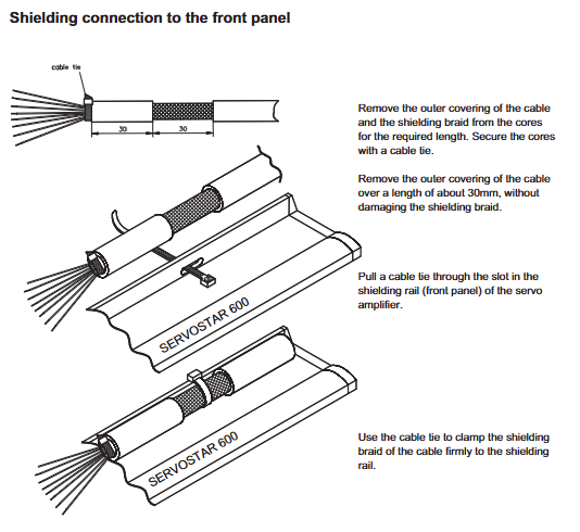
Feedback devices: resolver (X2, SubD9), encoder (X1, SubD15), shielding layer grounded through front-end shielding rail.
Grounding system: Distinguish between AGND (analog ground), DGND (digital ground), XGND (24V ground), and PGND (communication ground), and ensure reliable connection to the cabinet grounding.
Debugging and parameter settings
(1) Debugging Tools and Preparation
Software requirements: Use DRIVE. EXE software (installed on Windows system, minimum Pentium I/8MB memory), connect PC and amplifier (X6) through RS232 null mode cable;
Preliminary inspection: Confirm that the hardware version matches the manual. If the storage exceeds 1 year, the capacitor needs to be recharged (single-phase 230VAC applied to L1/L2 for 30 minutes), and the wiring should comply with the drawings.
(2) Quick debugging steps
Power on initialization: First, turn on the 24V auxiliary power supply. After 30 seconds, the display screen will show the current level (such as "3" representing 3A). If there are no fault codes (such as F02=overvoltage, F04=feedback fault), it is normal;
Software connection: Start DRIVE. EXE, select the COM port, establish communication, and upload parameters;
Basic configuration:
Basic settings: Select power supply voltage, phase loss response (warning n05/fault F19), unit (speed/position unit);
Motor configuration: Select the motor model from the database and enable the brake function (if necessary);
Feedback configuration: Select the feedback type (such as resolver/FBTYPE=0), save the parameters, and cold start;
Motor jogging: Enable hardware (X3/15+24V) and software (Shift+F12), enter "Speed" mode, set safe speed (such as 100rpm), and start jogging test.

Fault handling and maintenance
(1) Fault codes and troubleshooting
Troubleshooting measures for fault code causes
F01 heat sink overheating check ventilation, clean fan filter, reduce load
F02 DC bus overvoltage check brake resistor connection, reduce braking energy (such as extending deceleration time)
F04 feedback fault check feedback cable connection and shielding, confirm feedback type parameters
F05 DC bus undervoltage check main power supply voltage, fuse, confirm phase loss protection settings
F19 main power supply phase loss check the main power supply wiring and confirm that the input voltage meets the requirements
(2) Daily maintenance
Cleaning: Wipe the outer shell with isopropanol, clean the internal dust with the manufacturer, and clean the fan filter with a dry brush;
Storage: Original packaging storage (-25~55 ℃, humidity 5-95%, no condensation), capacitor restoration is required for over 1 year;
Repair and disposal: Only the manufacturer can repair, and scrapping must comply with the WEEE Directive (2002/96/EC). Contact the manufacturer for recycling.
Expansion options and accessories
Restart Lock Option (- AS -): Compliant with EN 954-1, it controls the safety relay through external signals to cut off the output stage drive power and prevent accidental restarts. It is suitable for debugging/maintenance scenarios;
Expansion card:
I/O expansion card (- I/O-14/08-): Added 14 inputs/8 outputs for triggering motion tasks;
Communication expansion cards: PROFIBUS (supporting DP protocol), SERCOS (fiber optic connection), EtherCAT (RJ45 interface), etc;
Special accessories: Encoder power supply (SINCOS, max 400mA), terminal adapter (for encoders without built-in terminal resistors), Hall Dongle (for encoders without commutation information).


- ABB
- General Electric
- EMERSON
- Honeywell
- HIMA
- ALSTOM
- Rolls-Royce
- MOTOROLA
- Rockwell
- Siemens
- Woodward
- YOKOGAWA
- FOXBORO
- KOLLMORGEN
- MOOG
- KB
- YAMAHA
- BENDER
- TEKTRONIX
- Westinghouse
- AMAT
- AB
- XYCOM
- Yaskawa
- B&R
- Schneider
- Kongsberg
- NI
- WATLOW
- ProSoft
- SEW
- ADVANCED
- Reliance
- TRICONEX
- METSO
- MAN
- Advantest
- STUDER
- KONGSBERG
- DANAHER MOTION
- Bently
- Galil
- EATON
- MOLEX
- DEIF
- B&W
- ZYGO
- Aerotech
- DANFOSS
- Beijer
- Moxa
- Rexroth
- Johnson
- WAGO
- TOSHIBA
- BMCM
- SMC
- HITACHI
- HIRSCHMANN
- Application field
- XP POWER
- CTI
- TRICON
- STOBER
- Thinklogical
- Horner Automation
- Meggitt
- Fanuc
- Baldor
- SHINKAWA
- Other Brands


