
SERVOSTAR ™ 601... 620 digital servo amplifier (S600 series)
Version and Compatibility: The document version is the 12th edition of December 2015, applicable to hardware version 05.40, and requires a specific firmware version (such as firmware ≥ 8.50_ND0/ND1 for hardware version 05.40). Different hardware versions correspond to different firmware requirements and functional support (such as BiSS/EtherCAT support requiring specific firmware).
Core Identification and Compliance: The product complies with CE, UL, cUL, GOST-R and other standards, with UL file number E217428, following the EMC Directive (2014/30/EC), Low Voltage Directive (2014/35/EC), protection level IP20, and pollution level 2.
SERVOSTAR ™ 601... 620 digital servo amplifier (S600 series)
Basic information of the document
Product range: Covering SERVOSTAR 601-620 series digital servo amplifiers, rated current 1.5-20A, suitable for specific brushless synchronous servo motors, supporting torque, speed, and position closed-loop control.
Version and Compatibility: The document version is the 12th edition of December 2015, applicable to hardware version 05.40, and requires a specific firmware version (such as firmware ≥ 8.50_ND0/ND1 for hardware version 05.40). Different hardware versions correspond to different firmware requirements and functional support (such as BiSS/EtherCAT support requiring specific firmware).
Core Identification and Compliance: The product complies with CE, UL, cUL, GOST-R and other standards, with UL file number E217428, following the EMC Directive (2014/30/EC), Low Voltage Directive (2014/35/EC), protection level IP20, and pollution level 2.
Safety and operational standards
(1) Personnel qualification requirements
Transportation: Personnel who need to master the operation of electrostatic sensitive components;
Unpacking and installation: Electrical professionals;
Debugging: Professional personnel with knowledge of electrical and drive technology must comply with IEC 60364/60664 and national safety regulations.
(2) Key safety warning
Risk of electric shock: During equipment operation, there is a high voltage of up to 900V. After power failure, dangerous voltage may remain in the capacitor. It is necessary to wait for at least 5 minutes to confirm that the DC bus voltage is below 50V before operation; It must be reliably grounded (PE bus), otherwise it may cause fatal electric shock.
Hot air hazard: The surface temperature of the equipment may exceed 80 ℃, and it needs to be cooled to below 40 ℃ before touching to avoid burns.
Automatic restart risk: When the parameter AENA is set to 1, the device may automatically restart after power on, voltage drop, or power failure recovery. Warning signs should be posted and the dangerous area should be powered on when no one is present.
Prohibited scenarios: Not suitable for explosive environments, corrosive/conductive environments, non grounded/asymmetrically grounded power grids (voltage>240V), and ship/offshore applications; Using a servo amplifier alone to control the brake cannot guarantee functional safety and requires additional mechanical braking.
(3) Operation restrictions
It can only operate in a closed distribution cabinet, with an ambient temperature of 0-45 ℃ (rated 2.5%/K for 45-55 ℃) and an altitude of ≤ 1000m (rated 1.5%/100m for 1000-2500m);
Only use copper wire for wiring, and the wire diameter must comply with EN 60204 or NEC 310-16 standards (60 ℃/75 ℃ column).
Product Technical Parameters
(1) Core electrical parameters
Parameter Range
Rated supply voltage 3 × 208V (-10%) -480V (+10%) (50/60Hz)
DC bus voltage 260-675V (rated), protection threshold 450-900V
Rated output current (rms) 1.5A (601) -20A (620), peak current is 2-2.8 times rated (up to 5s)
Output stage clock frequency 8kHz (16kHz can be set below 400V)
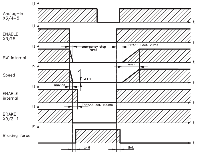
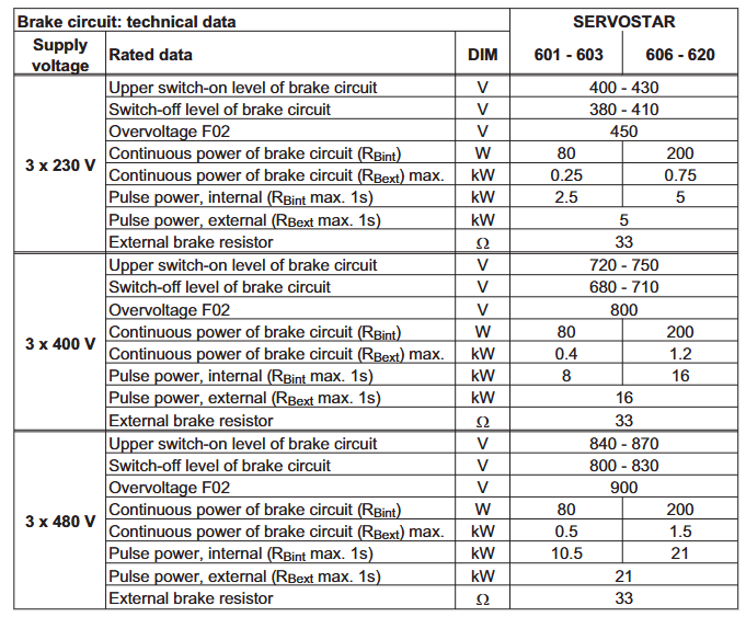
The braking circuit is equipped with a built-in braking resistor (80W for 601/603 and 200W for 606-620), and supports external braking resistors (maximum power 0.25-1.5kW)
(2) Interface and Control
Analog input: 2-channel differential input (± 10V, resolution 14bit/12bit), supporting speed/torque settings;
Analog output: 2 channels (± 10V, 10 bit resolution), default output actual speed and actual current;
Digital I/O: 4-channel input (24V, compliant with IEC 61131-2), 2-channel open collector output+1-channel relay output (BTB/RTO, used for emergency stop circuit);
Communication interface: Integrated CANopen (default 500kBaud, supporting DS301/DS402 protocol), RS232 (for PC debugging), expandable interfaces such as PROFIBUS, SERCOS, DeviceNet, EtherCAT, SynqNet, etc.
Feedback support: solver (X2), sine encoder (BiSS/EnDet/HIPERFACE, X1), incremental encoder (X5), supports encoder simulation (A quad B/SSI output).
Installation process
(1) Mechanical installation
Installation position: Vertically installed on the conductive grounding mounting plate, with reserved heat dissipation space around (such as 601-610 width of 70mm, above ≥ 40mm, below ≥ 70mm);
Fixing method: Use M5 hexagon socket screws (EN 4762) with a torque of 3.5Nm;
Protection requirements: Avoid approaching equipment with strong magnetic fields. The distribution cabinet should be forcibly ventilated to ensure that the ambient temperature is ≤ 45 ℃.
(2) Electrical installation
Wiring specifications: Power lines and control lines should be wired separately (spacing ≥ 200mm), motor cable length ≤ 25m (motor choke coil 3YL should be added if exceeding 25m), and both ends of the shielding layer should be grounded;
Key Connection:
Main power supply (X0A/X0B): 3-phase+PE, requiring external fuses (e.g. 6AT for 601/603, 10AT for 606/610, 20AT for 614/620);
DC bus (X7): Multi axis system can be connected in parallel, with a total rated current of ≤ 40A and a line length of ≤ 200mm (shielding is required for lines exceeding 200mm);
Motor (X9): including brake control (24V, max 2A), voltage drop needs to be confirmed;
- OMRON
- ABB
- General Electric
- EMERSON
- Honeywell
- HIMA
- ALSTOM
- Rolls-Royce
- MOTOROLA
- Rockwell
- Siemens
- Woodward
- YOKOGAWA
- FOXBORO
- KOLLMORGEN
- MOOG
- KB
- YAMAHA
- BENDER
- TEKTRONIX
- Westinghouse
- AMAT
- AB
- XYCOM
- Yaskawa
- B&R
- Schneider
- KONGSBERG
- NI
- WATLOW
- ProSoft
- SEW
- ADVANCED
- Reliance
- TRICONEX
- METSO
- MAN
- Advantest
- STUDER
- DANAHER MOTION
- Bently
- Galil
- EATON
- MOLEX
- DEIF
- B&W
- ZYGO
- Aerotech
- DANFOSS
- Beijer
- Moxa
- Rexroth
- Johnson
- WAGO
- TOSHIBA
- BMCM
- SMC
- HITACHI
- HIRSCHMANN
- Application field
- XP POWER
- CTI
- TRICON
- STOBER
- Thinklogical
- Horner Automation
- Meggitt
- Fanuc
- Baldor
- SHINKAWA
- Other Brands
- UniOP
- KUKA
- Iba
- Beckhoff
-
 OMRON B7AM-8B16 I/O Terminal Block
 -
 Fanuc A06B-6110-H026 Power Supply Module
 -
 Schneider TSXETG3021 Ethernet Gateway
 -
 OMRON CS1W-CLK21-V1 Controller Link Unit
 -
 NP1W6406T-Z704 PLC I/O Module
 -
 OMRON CJ1W-DA08C Analog Output Module
 -
 Yaskawa 3G3HV-A4022-CE AC Drive
 -
 OMRON NB7W-TW01B CP1L-EL20DR-D Power Panel
 -
 OMRON C500-NC103-E Position Control Unit
 -
 Steag Hamatech PLC DCS Servo Control System
 -
 Siemens 6SN1123-1AA00-0DA1 Power Supply Module
 -
 GE IC693CHS391H CPU & AD693CMM301A PLC Module
 -
 Siemens 6FC5303-0AF23-1AA1 PLC Control Panel
 -
 Square D CM4000T PowerLogic Circuit Monitor J1 F16
 -
 Siemens 6FX5002-5DG10-1BA0 MOTION-CONNECT 500 Cable
 -
 Schmersal SRB324ST 101195504 Safety Relay 24V
 -
 Mitsubishi 15050-PR02A PLC Circuit Board Module
 -
 OMRON CQM1-AD041 Analog Input PLC Module
 -
 Beckhoff EL5042 EtherCAT PLC Terminal Module
 -
 OMRON C200HW-MC402-E Motion Control Unit
 -
 C36TC0UA1100 Industrial Temperature Controller
 -
 NL8048BC24 12 Industrial Control LCD Module
 -
 OMRON R88D Servo Drive and Motor System
 -
 OMRON CS1W CLK21 V1 Controller Link Module
 -
 OMRON YASKAWA R7M A20030 S1 D Servo Motor
 -
 SIEMENS 6AV2128 3KB06 0AX1 Unified Comfort Panel
 -
 Schneider Electric METSEPM8240 PowerLogic Meter
 -
 Advanced AMCI 1PLC 1 31F Programmable Limit Switch
 -
 ABB PM582 ETH Programmable Logic Processor
 -
 SIEMENS 6FC5110 0CB01 0AA0 CPU Control Board
 -
 Schleicher P03GS13A CPU Module
 -
 Siemens 6SN1123-1AA00-0BA1 Power Module
 -
 Mitsubishi A1S61PN Power Supply Module
 -
 Yaskawa CPS-IONB DC Power Supply Module
 -
 Siemens 6ES7215-2BD00 CPU 215-2
 -
 Mitsubishi A2ACPU MELSEC PLC System Kit
 -
 ProSoft 3150-MCM Communication Module
 -
 Mitsubishi OSE104ET Incremental Encoder
 -
 OMRON CJ1W-AD081-V1 Analog Input Module
 -
 Broadcom BCM5464A1KRB Quad Port Ethernet IC
 -
 Modicon M221-24IO TM221C24 PLC 24 PNP Transistor
 -
 Allen-Bradley 1321-3R160-B Line Reactor 3R160B
 -
 Beckhoff CX1020-0012 Embedded PLC Module Specs
 -
 Turck BL20-PF-24VDC-D Power Feed Module Specs
 -
 Siemens 6SY7000-0AC37 Power Supply Module
 -
 Yaskawa SGDH-10DE-OY 1kW 400V Servo Drive Specs
 -
 Omron 3G3SV-BB015-E 1.5kW 220V VFD Specs
 -
 Uni-Pro CPU91-PLC J 23.020167X Processor Module
 -
 PASABAN MTC-3044 PLC Rack Power Supply 4835-A
 -
 XYCOM 3015T Operator Interface Panel BIN4.4.4
 -
 OMRON CJ1W-MD261 Mixed I/O Module
 -
 Omron NJ301-1100 PLC CPU eCat EIP Specs
 -
 Omron F500-C15-ETN Vision System PLC Module
 -
 Modicon M241-24IO TM/T2UK PLC with Ethernet
 -
 SIXNET YS-800-001 RTU PLC Module
 -
 BEMAC UST-202-D Interface Board 1307D V08B2
 -
 Yaskawa JANCD-MMOIC-02 Drive Circuit Board
 -
 ABB 3BSE005028R1 SDCS-COM-1 Comm Board
 -
 Omron 3G3MX2-A4110 A4150 Inverter Drives Specs
 -
 KEYENCE CA-E100 PLC Module
 -
 GE IC693ALG223-GB Analog Input Module Specs
 -
 ABB BAILEY IMMFP01 Multi Function Processor System
 -
 SIEMENS 6FC5372 0AA00 0AA1 NCU 7202 Controller
 -
Modicon TM241CE4 40I O Transistor Programmable Controller
-
 SIEMENS 6ES7 315 2EH13 0AB0 CPU 3152 PN DP
 -
 NORIS A1 91 PCB Card Rack Module System
 -
 SIEMENS 6ES7 313 5BE01 0AB0 Compact CPU
 -
 SCHNEIDER ELECTRIC S144B MICROLOGIC 60A Trip Unit
 -
 CNI PLC269 v3 Control Module Board Rev H
 -
ABB BAILEY IIMCP02 Processor Module
-
 OMRON NT20S ST121 EV3 Operator Interface Terminal
 -
 OMRON NS-CA001 Video Input Unit
 -
 GE Fanuc IC695CHS012 RX3i Backplane
 -
 Allen Bradley 2711E-K14C6 PanelView 1400e Terminal
 -
 Siemens Sinamics CCB 10000432.71 Power Cell
 -
 Siemens 6SL3210-1SE21-8UA0 Power Module PM340
 -
 Yaskawa CIMR-F7A20P4 AC Drive
 -
 Beckhoff EP1918-0002 EtherCAT Box I/O Module
 -
 OMRON CQM1-TC001 Temperature Control Module
 -
 GE Fanuc SGHA36AT0400 Industrial Contactor
 -
 OMRON NJ501-1500 PLC Machine Automation Controller
 -
 Mitsubishi MAZAK QX084 Power Supply MELDAS 500 CNC
 -
 B&R 0AC808.9 PLC Automation Module
 -
 OMRON CP1H-XA40DT1-D PLC Module
 -
 G&W Electric PLC15 5111 011 15kV Capnut Assembly
 -
 GE DS200SLCCG3AGH PCB Circuit Board
 -
 Siemens SINUMERIK 6FC3981-4FD PLC Extension
 -
 OMRON F300-DC I/O Image Processing Unit
 -
 FANUC A06B-0314-B002 AC Servo Motor
 -
 GC-S84 Programmable Controller Logic Module
 -
 PASABAN MONTELEC MTC3001-DC Drive Control PLC
 -
 Allen Bradley 100E460EJ11 Auxiliary Contactor
 -
 Bosch Rexroth 1070075337-101 Card Parameters
 -
 HMS Anybus AB7646-F Gateway Specifications
 -
 Bosch 062633-303401 CNC Servo PLC Card
 -
 TI 500-5023 Series PLC Power Supply
 -
 Siemens C98043-A7002-L1-12 Circuit Board
 -
 Omron E5CC-RX3A5M-000 Controller
 -
 CN-8032-L Profinet Network Adapter Module
 -
 Siemens 3TK2804-0BB4 Safety Relay Details
 -
 Toledo TTLM-2-1M I/O Load Module
 -
 NORIS A1-91 PLC Rack Board Specifications
 -
 Mitsubishi A3ACPUR21 MELSEC PLC CPU Module
 -
 Beckhoff EP7041‑3002 EtherCAT Box Digital Input Module
 -
 REER EOS2E 1053 EOS2R 1053 Safety Light Curtain
 -
 Mitsubishi Q80BD-J71BR11 MELSECNET/H Interface Board
 -
 Omron 3G3IV-B4220-EV2 VFD 400V 22kW
 -
 Allen-Bradley 96844671 1785-LT3 PLC-5/12 Processor Module
 -
 Pasaban MTC3001-DC Drive Control PLC Module
 -
 Omron CJ1M-CPU11 V4.0 PLC CPU Module
 -
 ABB CM579-PNIO B3 Communication Module
 -
 B&R X20 AI 4221 Analog Module
 -
 Siemens 6SY7000-0AC80 PLC Module
 -
 GE 531X300CCHAFM5 Control Card
 -
 AB 810-A15C Inverse Time Relay
 -
 WITTENSTEIN LP120X-MF2-20 Planetary Gear
 -
 Mitsubishi Kakoki E-01B-4130 PLC I/O Modules
 -
 ABB DSQC643 Safety Control Board
 -
 Siemens G26004-A2105-P100-2 PCB
 -
 OMRON F350-C10E Image Processing Unit
 -
 FUJI UG430H-TS1 HMI Touch Panel
 -
 Westronics CB100188-01 Rev F Board
 -
 Siemens 7MH4900-3AA01 Weighing Module
 -
 Gilbert & Nash Tracker 2000 Control Cabinet
 -
 OMRON CJ1M-CPU22 CPU Unit
 -
 OMRON F3SJ-E0625P25 Light Curtain
 -
 Siemens 3VA2340-5HL32-0AA0 Breaker
 -
 Mitsubishi Melsec A61P A2NCPU PLC System


