
SERVOSTAR ™ 601... 620 digital servo amplifier (S600 series)
Version and Compatibility: The document version is the 12th edition of December 2015, applicable to hardware version 05.40, and requires a specific firmware version (such as firmware ≥ 8.50_ND0/ND1 for hardware version 05.40). Different hardware versions correspond to different firmware requirements and functional support (such as BiSS/EtherCAT support requiring specific firmware).
Core Identification and Compliance: The product complies with CE, UL, cUL, GOST-R and other standards, with UL file number E217428, following the EMC Directive (2014/30/EC), Low Voltage Directive (2014/35/EC), protection level IP20, and pollution level 2.
SERVOSTAR ™ 601... 620 digital servo amplifier (S600 series)
Basic information of the document
Product range: Covering SERVOSTAR 601-620 series digital servo amplifiers, rated current 1.5-20A, suitable for specific brushless synchronous servo motors, supporting torque, speed, and position closed-loop control.
Version and Compatibility: The document version is the 12th edition of December 2015, applicable to hardware version 05.40, and requires a specific firmware version (such as firmware ≥ 8.50_ND0/ND1 for hardware version 05.40). Different hardware versions correspond to different firmware requirements and functional support (such as BiSS/EtherCAT support requiring specific firmware).
Core Identification and Compliance: The product complies with CE, UL, cUL, GOST-R and other standards, with UL file number E217428, following the EMC Directive (2014/30/EC), Low Voltage Directive (2014/35/EC), protection level IP20, and pollution level 2.
Safety and operational standards
(1) Personnel qualification requirements
Transportation: Personnel who need to master the operation of electrostatic sensitive components;
Unpacking and installation: Electrical professionals;
Debugging: Professional personnel with knowledge of electrical and drive technology must comply with IEC 60364/60664 and national safety regulations.
(2) Key safety warning
Risk of electric shock: During equipment operation, there is a high voltage of up to 900V. After power failure, dangerous voltage may remain in the capacitor. It is necessary to wait for at least 5 minutes to confirm that the DC bus voltage is below 50V before operation; It must be reliably grounded (PE bus), otherwise it may cause fatal electric shock.
Hot air hazard: The surface temperature of the equipment may exceed 80 ℃, and it needs to be cooled to below 40 ℃ before touching to avoid burns.
Automatic restart risk: When the parameter AENA is set to 1, the device may automatically restart after power on, voltage drop, or power failure recovery. Warning signs should be posted and the dangerous area should be powered on when no one is present.
Prohibited scenarios: Not suitable for explosive environments, corrosive/conductive environments, non grounded/asymmetrically grounded power grids (voltage>240V), and ship/offshore applications; Using a servo amplifier alone to control the brake cannot guarantee functional safety and requires additional mechanical braking.
(3) Operation restrictions
It can only operate in a closed distribution cabinet, with an ambient temperature of 0-45 ℃ (rated 2.5%/K for 45-55 ℃) and an altitude of ≤ 1000m (rated 1.5%/100m for 1000-2500m);
Only use copper wire for wiring, and the wire diameter must comply with EN 60204 or NEC 310-16 standards (60 ℃/75 ℃ column).
Product Technical Parameters
(1) Core electrical parameters
Parameter Range
Rated supply voltage 3 × 208V (-10%) -480V (+10%) (50/60Hz)
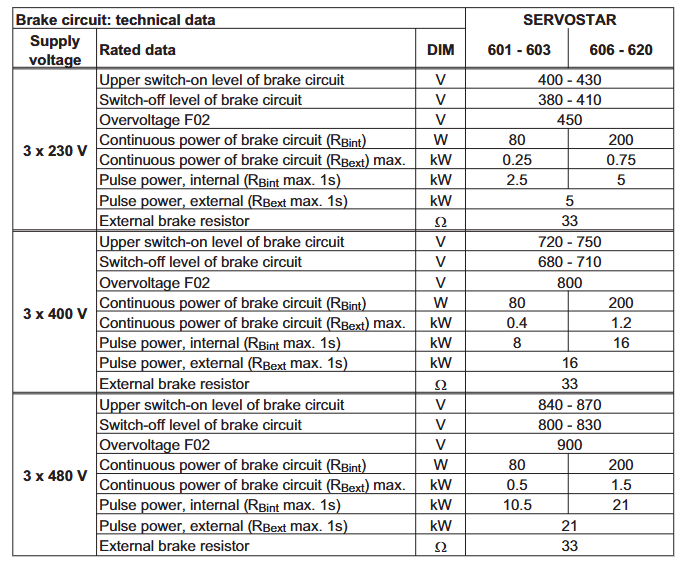
DC bus voltage 260-675V (rated), protection threshold 450-900V
Rated output current (rms) 1.5A (601) -20A (620), peak current is 2-2.8 times rated (up to 5s)
Output stage clock frequency 8kHz (16kHz can be set below 400V)
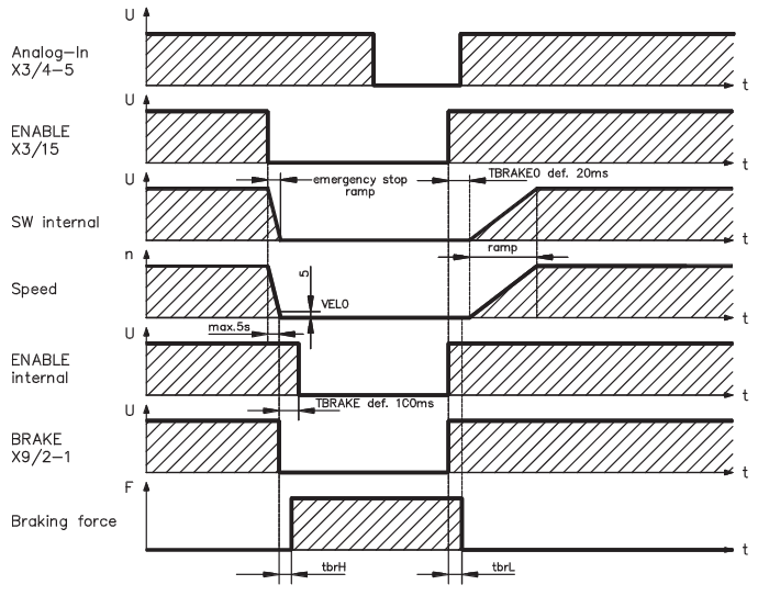
The braking circuit is equipped with a built-in braking resistor (80W for 601/603 and 200W for 606-620), and supports external braking resistors (maximum power 0.25-1.5kW)
(2) Interface and Control
Analog input: 2-channel differential input (± 10V, resolution 14bit/12bit), supporting speed/torque settings;
Analog output: 2 channels (± 10V, 10 bit resolution), default output actual speed and actual current;
Digital I/O: 4-channel input (24V, compliant with IEC 61131-2), 2-channel open collector output+1-channel relay output (BTB/RTO, used for emergency stop circuit);
Communication interface: Integrated CANopen (default 500kBaud, supporting DS301/DS402 protocol), RS232 (for PC debugging), expandable interfaces such as PROFIBUS, SERCOS, DeviceNet, EtherCAT, SynqNet, etc.
Feedback support: solver (X2), sine encoder (BiSS/EnDet/HIPERFACE, X1), incremental encoder (X5), supports encoder simulation (A quad B/SSI output).
Installation process
(1) Mechanical installation
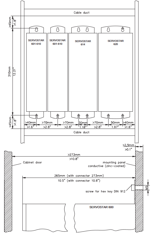
Installation position: Vertically installed on the conductive grounding mounting plate, with reserved heat dissipation space around (such as 601-610 width of 70mm, above ≥ 40mm, below ≥ 70mm);
Fixing method: Use M5 hexagon socket screws (EN 4762) with a torque of 3.5Nm;
Protection requirements: Avoid approaching equipment with strong magnetic fields. The distribution cabinet should be forcibly ventilated to ensure that the ambient temperature is ≤ 45 ℃.
(2) Electrical installation
Wiring specifications: Power lines and control lines should be wired separately (spacing ≥ 200mm), motor cable length ≤ 25m (motor choke coil 3YL should be added if exceeding 25m), and both ends of the shielding layer should be grounded;
Key Connection:
Main power supply (X0A/X0B): 3-phase+PE, requiring external fuses (e.g. 6AT for 601/603, 10AT for 606/610, 20AT for 614/620);
DC bus (X7): Multi axis system can be connected in parallel, with a total rated current of ≤ 40A and a line length of ≤ 200mm (shielding is required for lines exceeding 200mm);
Motor (X9): including brake control (24V, max 2A), voltage drop needs to be confirmed;
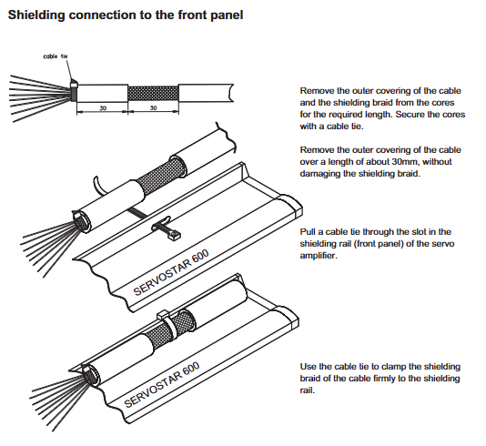
Feedback devices: resolver (X2, SubD9), encoder (X1, SubD15), shielding layer grounded through front-end shielding rail.
Grounding system: Distinguish between AGND (analog ground), DGND (digital ground), XGND (24V ground), and PGND (communication ground), and ensure reliable connection to the cabinet grounding.
Debugging and parameter settings
(1) Debugging Tools and Preparation
Software requirements: Use DRIVE. EXE software (installed on Windows system, minimum Pentium I/8MB memory), connect PC and amplifier (X6) through RS232 null mode cable;
Preliminary inspection: Confirm that the hardware version matches the manual. If the storage exceeds 1 year, the capacitor needs to be recharged (single-phase 230VAC applied to L1/L2 for 30 minutes), and the wiring should comply with the drawings.
(2) Quick debugging steps
Power on initialization: First, turn on the 24V auxiliary power supply. After 30 seconds, the display screen will show the current level (such as "3" representing 3A). If there are no fault codes (such as F02=overvoltage, F04=feedback fault), it is normal;
Software connection: Start DRIVE. EXE, select the COM port, establish communication, and upload parameters;
Basic configuration:
Basic settings: Select power supply voltage, phase loss response (warning n05/fault F19), unit (speed/position unit);
Motor configuration: Select the motor model from the database and enable the brake function (if necessary);
Feedback configuration: Select the feedback type (such as resolver/FBTYPE=0), save the parameters, and cold start;
Motor jogging: Enable hardware (X3/15+24V) and software (Shift+F12), enter "Speed" mode, set safe speed (such as 100rpm), and start jogging test.
Fault handling and maintenance
(1) Fault codes and troubleshooting
Troubleshooting measures for fault code causes
F01 heat sink overheating check ventilation, clean fan filter, reduce load
F02 DC bus overvoltage check brake resistor connection, reduce braking energy (such as extending deceleration time)
F04 feedback fault check feedback cable connection and shielding, confirm feedback type parameters
F05 DC bus undervoltage check main power supply voltage, fuse, confirm phase loss protection settings
F19 main power supply phase loss check the main power supply wiring and confirm that the input voltage meets the requirements
(2) Daily maintenance
Cleaning: Wipe the outer shell with isopropanol, clean the internal dust with the manufacturer, and clean the fan filter with a dry brush;
Storage: Original packaging storage (-25~55 ℃, humidity 5-95%, no condensation), capacitor restoration is required for over 1 year;
Repair and disposal: Only the manufacturer can repair, and scrapping must comply with the WEEE Directive (2002/96/EC). Contact the manufacturer for recycling.
Expansion options and accessories
Restart Lock Option (- AS -): Compliant with EN 954-1, it controls the safety relay through external signals to cut off the output stage drive power and prevent accidental restarts. It is suitable for debugging/maintenance scenarios;
Expansion card:
I/O expansion card (- I/O-14/08-): Added 14 inputs/8 outputs for triggering motion tasks;
Communication expansion cards: PROFIBUS (supporting DP protocol), SERCOS (fiber optic connection), EtherCAT (RJ45 interface), etc;
Special accessories: Encoder power supply (SINCOS, max 400mA), terminal adapter (for encoders without built-in terminal resistors), Hall Dongle (for encoders without commutation information).
- OMRON
- ABB
- General Electric
- EMERSON
- Honeywell
- HIMA
- ALSTOM
- Rolls-Royce
- MOTOROLA
- Rockwell
- Siemens
- Woodward
- YOKOGAWA
- FOXBORO
- KOLLMORGEN
- MOOG
- KB
- YAMAHA
- BENDER
- TEKTRONIX
- Westinghouse
- AMAT
- AB
- XYCOM
- Yaskawa
- B&R
- Schneider
- KONGSBERG
- NI
- WATLOW
- ProSoft
- SEW
- ADVANCED
- Reliance
- TRICONEX
- METSO
- MAN
- Advantest
- STUDER
- DANAHER MOTION
- Bently
- Galil
- EATON
- MOLEX
- DEIF
- B&W
- ZYGO
- Aerotech
- DANFOSS
- Beijer
- Moxa
- Rexroth
- Johnson
- WAGO
- TOSHIBA
- BMCM
- SMC
- HITACHI
- HIRSCHMANN
- Application field
- XP POWER
- CTI
- TRICON
- STOBER
- Thinklogical
- Horner Automation
- Meggitt
- Fanuc
- Baldor
- SHINKAWA
- Other Brands
- UniOP
- KUKA
- Iba
- Beckhoff
-
 OMRON C60H C6DR DE V1 Sysmac PLC
 -
 MITSUBISHI ELECTRIC A2ACPU21 S1 CPU Module
 -
 ABB BAILEY INNPM12 Network Process Module
 -
 HONEYWELL 620 0073C IPC PLC Module
 -
 Mitsubishi 15050 PR02B PLC Circuit Board
 -
 SIEMENS 6SY7000 0AC37 Drive Control Module
 -
 OMRON TJ2 ECT16 Traxial EtherCAT Controller
 -
 GE Fanuc IC698PSD300D Power Supply Module
 -
 Texas Instruments Series 505 16 Position Base
 -
 OMRON YASKAWA SGDH 10DE OY Servo Drive
 -
 Allen‑Bradley 440G-MT Safety Interlock Switch Specs
 -
 Rubycon PD27A 24V 8A Power Supply Module
 -
 SK-H1-GDB1-F11D PLC Gate Driver Board Kit
 -
 VIPA 441-4UA14 451-4UA14 PLC Module Rack
 -
 Mitsubishi FX5U-80MT ESS PLC Controller Specs
 -
 Mitsubishi Q64TCRTN Temperature PLC Module
 -
 GE 1C31170G Rev10 PLC Circuit Board Module
 -
 Schneider TWDLMDA40DTK PLC Controller Module
 -
 Omron FQM1-MMA22 Motion Control Module Specs
 -
 OMRON CJ1W-NCF71 Position Control Unit Specs
 -
 Schneider TSXETY4103 Ethernet Module
 -
 Mitsubishi Q12PHCPU Process CPU
 -
 Yaskawa 3G3HV-A4022-CE AC Drive
 -
 Cincinnati Milacron 3-533-0669G Temperature Control Board
 -
 Allen Bradley 20AC030A3AYNANC0 PowerFlex 70 Drive
 -
 Siemens 6ES7314-6BG03-0AB0 CPU 314C-2 DP
 -
 Carrier 17EX54007903 PLC Module
 -
 OMRON CS1W-V600C12 ID Controller Module
 -
 Honeywell 51402755-100 PCB Card
 -
 Heidenhain ECN 113 Rotary Encoder
 -
 OMRON B7AM-8B16 I/O Terminal Block
 -
 Fanuc A06B-6110-H026 Power Supply Module
 -
 Schneider TSXETG3021 Ethernet Gateway
 -
 OMRON CS1W-CLK21-V1 Controller Link Unit
 -
 NP1W6406T-Z704 PLC I/O Module
 -
 OMRON CJ1W-DA08C Analog Output Module
 -
 Yaskawa 3G3HV-A4022-CE AC Drive
 -
 OMRON NB7W-TW01B CP1L-EL20DR-D Power Panel
 -
 OMRON C500-NC103-E Position Control Unit
 -
 Steag Hamatech PLC DCS Servo Control System
 -
 Siemens 6SN1123-1AA00-0DA1 Power Supply Module
 -
 GE IC693CHS391H CPU & AD693CMM301A PLC Module
 -
 Siemens 6FC5303-0AF23-1AA1 PLC Control Panel
 -
 Square D CM4000T PowerLogic Circuit Monitor J1 F16
 -
 Siemens 6FX5002-5DG10-1BA0 MOTION-CONNECT 500 Cable
 -
 Schmersal SRB324ST 101195504 Safety Relay 24V
 -
 Mitsubishi 15050-PR02A PLC Circuit Board Module
 -
 OMRON CQM1-AD041 Analog Input PLC Module
 -
 Beckhoff EL5042 EtherCAT PLC Terminal Module
 -
 OMRON C200HW-MC402-E Motion Control Unit
 -
 C36TC0UA1100 Industrial Temperature Controller
 -
 NL8048BC24 12 Industrial Control LCD Module
 -
 OMRON R88D Servo Drive and Motor System
 -
 OMRON CS1W CLK21 V1 Controller Link Module
 -
 OMRON YASKAWA R7M A20030 S1 D Servo Motor
 -
 SIEMENS 6AV2128 3KB06 0AX1 Unified Comfort Panel
 -
 Schneider Electric METSEPM8240 PowerLogic Meter
 -
 Advanced AMCI 1PLC 1 31F Programmable Limit Switch
 -
 ABB PM582 ETH Programmable Logic Processor
 -
 SIEMENS 6FC5110 0CB01 0AA0 CPU Control Board
 -
 Schleicher P03GS13A CPU Module
 -
 Siemens 6SN1123-1AA00-0BA1 Power Module
 -
 Mitsubishi A1S61PN Power Supply Module
 -
 Yaskawa CPS-IONB DC Power Supply Module
 -
 Siemens 6ES7215-2BD00 CPU 215-2
 -
 Mitsubishi A2ACPU MELSEC PLC System Kit
 -
 ProSoft 3150-MCM Communication Module
 -
 Mitsubishi OSE104ET Incremental Encoder
 -
 OMRON CJ1W-AD081-V1 Analog Input Module
 -
 Broadcom BCM5464A1KRB Quad Port Ethernet IC
 -
 Modicon M221-24IO TM221C24 PLC 24 PNP Transistor
 -
 Allen-Bradley 1321-3R160-B Line Reactor 3R160B
 -
 Beckhoff CX1020-0012 Embedded PLC Module Specs
 -
 Turck BL20-PF-24VDC-D Power Feed Module Specs
 -
 Siemens 6SY7000-0AC37 Power Supply Module
 -
 Yaskawa SGDH-10DE-OY 1kW 400V Servo Drive Specs
 -
 Omron 3G3SV-BB015-E 1.5kW 220V VFD Specs
 -
 Uni-Pro CPU91-PLC J 23.020167X Processor Module
 -
 PASABAN MTC-3044 PLC Rack Power Supply 4835-A
 -
 XYCOM 3015T Operator Interface Panel BIN4.4.4
 -
 OMRON CJ1W-MD261 Mixed I/O Module
 -
 Omron NJ301-1100 PLC CPU eCat EIP Specs
 -
 Omron F500-C15-ETN Vision System PLC Module
 -
 Modicon M241-24IO TM/T2UK PLC with Ethernet
 -
 SIXNET YS-800-001 RTU PLC Module
 -
 BEMAC UST-202-D Interface Board 1307D V08B2
 -
 Yaskawa JANCD-MMOIC-02 Drive Circuit Board
 -
 ABB 3BSE005028R1 SDCS-COM-1 Comm Board
 -
 Omron 3G3MX2-A4110 A4150 Inverter Drives Specs
 -
 KEYENCE CA-E100 PLC Module
 -
 GE IC693ALG223-GB Analog Input Module Specs
 -
 ABB BAILEY IMMFP01 Multi Function Processor System
 -
 SIEMENS 6FC5372 0AA00 0AA1 NCU 7202 Controller
 -
Modicon TM241CE4 40I O Transistor Programmable Controller
-
 SIEMENS 6ES7 315 2EH13 0AB0 CPU 3152 PN DP
 -
 NORIS A1 91 PCB Card Rack Module System
 -
 SIEMENS 6ES7 313 5BE01 0AB0 Compact CPU
 -
 SCHNEIDER ELECTRIC S144B MICROLOGIC 60A Trip Unit
 -
 CNI PLC269 v3 Control Module Board Rev H
 -
ABB BAILEY IIMCP02 Processor Module
-
 OMRON NT20S ST121 EV3 Operator Interface Terminal
 -
 OMRON NS-CA001 Video Input Unit
 -
 GE Fanuc IC695CHS012 RX3i Backplane
 -
 Allen Bradley 2711E-K14C6 PanelView 1400e Terminal
 -
 Siemens Sinamics CCB 10000432.71 Power Cell
 -
 Siemens 6SL3210-1SE21-8UA0 Power Module PM340
 -
 Yaskawa CIMR-F7A20P4 AC Drive
 -
 Beckhoff EP1918-0002 EtherCAT Box I/O Module
 -
 OMRON CQM1-TC001 Temperature Control Module
 -
 GE Fanuc SGHA36AT0400 Industrial Contactor
 -
 OMRON NJ501-1500 PLC Machine Automation Controller
 -
 Mitsubishi MAZAK QX084 Power Supply MELDAS 500 CNC
 -
 B&R 0AC808.9 PLC Automation Module
 -
 OMRON CP1H-XA40DT1-D PLC Module
 -
 G&W Electric PLC15 5111 011 15kV Capnut Assembly
 -
 GE DS200SLCCG3AGH PCB Circuit Board
 -
 Siemens SINUMERIK 6FC3981-4FD PLC Extension
 -
 OMRON F300-DC I/O Image Processing Unit
 -
 FANUC A06B-0314-B002 AC Servo Motor
 -
 GC-S84 Programmable Controller Logic Module
 -
 PASABAN MONTELEC MTC3001-DC Drive Control PLC
 -
 Allen Bradley 100E460EJ11 Auxiliary Contactor
 -
 Bosch Rexroth 1070075337-101 Card Parameters
 -
 HMS Anybus AB7646-F Gateway Specifications
 -
 Bosch 062633-303401 CNC Servo PLC Card
 -
 TI 500-5023 Series PLC Power Supply
 -
 Siemens C98043-A7002-L1-12 Circuit Board
 -
 Omron E5CC-RX3A5M-000 Controller


