
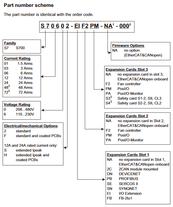
Kollmorgen S700 series digital servo amplifier
Software Configuration (DRIVE GUI. EXE)
Installation and Connection: Supports Windows 2000/XP/Vista/7, connects PC and amplifier X6 interface through RS232 cable (P7S2-232-9D), baud rate 38400bps, data bit 8, even check, stop bit 1, software automatically recognizes amplifier model and firmware version.
Core configuration module:
Motor configuration: Select the motor model (such as AKM series) from the database, or manually input parameters such as rated current, torque constant, inductance, etc., and perform the "Motor Probe" to detect the motor inductance and optimize the current loop gain.
Security configuration: The STO function requires setting the STO Status output (such as X3A/6) and associating it with the security controller through the ASCII command OxMODE70 to achieve periodic testing; The security card S3/S4 needs to be configured with SS1 activation signal (X30/1) and reset signal (X30/20) to ensure the correct triggering timing of the security function.
Sports configuration: Set the electronic gear ratio for the position ring (e.g. set PGEAR1=2 and PGEAR0=1 for a 1:2 gearbox), gain for the speed ring (Kp=0.5-2.0, Tn=0.01-0.1s), and automatically optimize control parameters through "Autotuning" to reduce tracking errors (fault F03).
Hardware switch configuration
Address and baud rate: Set the CANopen station address (1-99) and baud rate (10-1000kbit/s) through the amplifier front-end buttons. After setting, restart the 24V power supply to take effect. The baud rate encoding is as follows: "25" corresponds to 250kbit/s, and "50" corresponds to 500kbit/s.
Expansion card recognition: After inserting the expansion card into Slot 1/2/3, the amplifier will automatically recognize it when powered on. The function can be configured through the DRIVE GUI "Expansion Card" interface (such as setting the PROFIBUS address to 3 and the baud rate to 1.5Mbit/s). If the expansion card is not recognized, it is necessary to check whether it is installed properly (card buckle locking).
Troubleshooting and Maintenance
1、 Troubleshooting System
(1) Fault diagnosis tools and processes
Front end LED display diagnosis
The 3-character LED display on the front end of the amplifier is the core fault indicator unit, and different states correspond to different fault types:
Red flashing: Fault code (such as F01-F32), it is necessary to locate the problem based on the fault table, and the number of flashes corresponds to the fault number (such as flashing once is F01).
Yellow constantly on: EOT (end of travel) input latch (such as n10/n11), the motor needs to be moved in reverse to disengage from the limit sensor.
Red constantly on: FLASH memory verification error (F09), firmware needs to be re downloaded (via memory card or PC software).
- S - "display: STO function activated (STO1/STO2 Enable is 0V), check the safety circuit wiring or safety relay status.
Troubleshooting process
Preliminary inspection: Confirm if the power supply voltage (X0 terminal), 24V auxiliary power supply (X4A), and STO signal (X4A/3/X4B/6) are normal, disconnect the load to test the motor for independent operation, and eliminate mechanical jamming.
Parameter verification: Read parameters (such as motor current, speed, and bus voltage) through DRIVE GUI software, confirm that I2/rms/I2 peak does not exceed the rated value, and provide feedback parameters (FBTYPE, ENCVON) that match the actual feedback type.
Hardware testing: Measure the resistance of the motor winding (three-phase balance, deviation ≤ 5%), feedback cable continuity (if there is no open circuit between terminal X1 A+/A -), and check the temperature of the power module (triggering F01 when the heat sink exceeds 80 ℃).
(2) Common fault codes and solutions
Fault code, fault description, possible causes, and solutions
F01 heat sink overheating: 1. The ambient temperature exceeds 40 ℃; 2. Fan malfunction; 3. The load duty cycle is too high. 1. Increase forced air cooling (wind speed ≥ 2m/s); 2. Replace the fan (S701-S712 fan model DE-200454); 3. Reduce the frequency of motion or increase the motor model
F02 DC bus overvoltage: 1. Input voltage exceeds the rated value (such as S7xx0 exceeding 480VAC); 2. Excessive braking power (failure to consume regenerative energy in a timely manner); 3. External braking resistor not connected. 1. Check the grid voltage and install a three-phase stabilized power supply; 2. Increase the power of the external braking resistor (such as S72402 with a 23 Ω/4kW resistor); 3. Connect the external braking resistor to the X8 terminal (remove the X8/3-X8/4 shorting bar)
F03 tracking error exceeds tolerance
1. Position loop gain (Kp) is too low; 2. The load inertia ratio exceeds the set value; 3. The motor current limit is too small. 1. Increase Kp through DRIVE GUI (such as adjusting from 0.5 to 1.0); 2. Reset the load inertia ratio (S2-5~S2-7 switches or software parameters); 3. Increase I2/RMS/I2 peak (not exceeding the rated value of the motor)
F04 feedback fault 1. Feedback cable breakage/short circuit; 2. Feedback equipment damage (such as encoder); 3. FBTYPE parameter setting error: 1. Use a multimeter to measure the continuity of the feedback cable (e.g. X1 terminal A+/A - resistance should be ≥ 1k Ω); 2. Replace feedback devices (such as EnDat encoder ECN1313); 3. Match FBTYPE with feedback type (e.g. BiSS-C set to 33)
- OMRON
- ABB
- General Electric
- EMERSON
- Honeywell
- HIMA
- ALSTOM
- Rolls-Royce
- MOTOROLA
- Rockwell
- Siemens
- Woodward
- YOKOGAWA
- FOXBORO
- KOLLMORGEN
- MOOG
- KB
- YAMAHA
- BENDER
- TEKTRONIX
- Westinghouse
- AMAT
- AB
- XYCOM
- Yaskawa
- B&R
- Schneider
- KONGSBERG
- NI
- WATLOW
- ProSoft
- SEW
- ADVANCED
- Reliance
- TRICONEX
- METSO
- MAN
- Advantest
- STUDER
- DANAHER MOTION
- Bently
- Galil
- EATON
- MOLEX
- DEIF
- B&W
- ZYGO
- Aerotech
- DANFOSS
- Beijer
- Moxa
- Rexroth
- Johnson
- WAGO
- TOSHIBA
- BMCM
- SMC
- HITACHI
- HIRSCHMANN
- Application field
- XP POWER
- CTI
- TRICON
- STOBER
- Thinklogical
- Horner Automation
- Meggitt
- Fanuc
- Baldor
- SHINKAWA
- Other Brands
- UniOP
- KUKA
- Iba
- Beckhoff
-
 Basler DECS-100-B15 Digital AVR
 -
 Basler 9284900103 PS DECS-400N
 -
 Basler D4N3H1U Intertie Protection
 -
 Basler DECS-100-B15 A15 AVR
 -
 Basler KR4F Voltage Regulator
 -
 Basler BE26434 T14 Transformer
 -
 Basler SR8A-2B15B3A Regulator
 -
 Westinghouse 774B472A12 AR Relay
 -
Basler DECS-100-B15 AVR
-
 Basler XR2002F Regulator 110V
 -
 Basler SR125-E Static Regulator
 -
 Basler SSR 125-12 Regulator
 -
 Basler MOC2599 Motor Pot
 -
 Basler BE1-DFPR Feeder Relay
 -
 Basler CBS 305 Current Boost
 -
 Basler BE1-25 AutoSync
 -
 Basler MVC 300 Voltage Control
 -
 Basler BE3-25A AutoSync
 -
 Basler KR7FF Static Regulator
 -
 Basler 90-49000-100 Regulator
 -
 Basler 880 kVA Dry Type Transformer Specs
 -
 Basler Electric BE1-25 Sync-Check Relay Specs
 -
 Basler SSR 125-12 Voltage Regulator Specs
 -
 Basler Electric BE1-851 Overcurrent Relay Review
 -
Basler Electric 149D930G02 Control Sub-Assembly
-
 Basler Electric BE1-81O/UT Frequency Relay Specs
 -
 Basler Electric BE1-51/27C Overcurrent Relay
 -
 Basler Electric 149D956G02 Industrial Component
 -
Basler Electric BE1-51A Overcurrent Relay Specs
-
 Basler Electric BE1-40Q Loss of Excitation Relay
 -
 Basler DECS-200 Excitation Control System
 -
 Basler DECS-200 Voltage Regulator 56-277V AC / 125V DC
 -
 Basler BE1-87T Transformer Differential Relay
 -
 Basler RDP-110-S1 Protection Relay
 -
 Basler BE1-700V Digital Protective Relay
 -
 Basler BE1-951 Overcurrent Protection System
 -
 Basler DECS-300 Digital Excitation Control
 -
 Basler DECS-200 Digital Excitation Control
 -
 Basler DECS-200-1C Excitation Control System
 -
Basler DECS-200-1L Digital Excitation Control
-
 Basler Electric BE1-GPS Generator Protection System
 -
Basler Electric DECS-200-1C Digital Excitation Controller
-
 Basler Electric DECS125-15 Excitation Control with Power Module
 -
 Basler Electric BE1-87G Differential Relay
 -
 Basler Electric BE1-11 Protection System I5A3M2P2N0EA00
 -
Basler Electric DECS-200-1C Excitation Control System
-
Basler Electric BE1-11g Generator Protection Relay
-
 Basler Electric DECS 125-15-B2C1 V2.0.9 Excitation Control
 -
 Basler Electric BE1-81O/UT3ED1JA7N2F Frequency Relay
 -
Basler Electric BE1-81O/UT3EE1YB7N1F Frequency Relay
-
 Basler Electric DECS-200-1L Digital Excitation Control System
 -
Basler DECS125-15-B2C1 Excitation Control
-
 Basler 9507900205 SSR Retrofit Voltage Regulator
 -
 Basler BE2000E Digital Voltage Regulator
 -
 Basler BE1-GPS Generator Protection System
 -
Basler DECS-250-CN1CN1N Digital Excitation Control
-
 Basler DGC-2020 Genset Controller
 -
 Basler BE1-81O UT3ED1LA7N0F Frequency Relay (Variant)
 -
 Basler BE1-81O UT3EE1YA9S0F Frequency Relay (Variant)
 -
Basler BE1-81O Over/Under Frequency Relay
-
Basler DECS125-15 Digital Excitation Control
-
Basler Electric BE1-951 Overcurrent Protection System
-
 Basler Electric BE1-700V Digital Protective Relay
 -
 Basler Electric APR63-5 Automatic Voltage Regulator
 -
Basler Electric BE1-851 Overcurrent Protection System
-
Basler Electric DECS-250-LN1SN1N Excitation Control
-
 Basler Electric BE1-87T Transformer Differential Relay
 -
Basler Electric DECS-200-1L Excitation Control System
-
 Basler Electric 9310300100 DECS-300 Excitation Control
 -
 Basler Electric SSE-N 125-4.5KW Shunt Exciter Regulator
 -
 Basler Electric DGC-2020HD-5NS1DNSBA Genset Controller
 -
Basler Electric BE1-81-O/UT3EE1JB7N1F Frequency Relay
-
Basler Electric BE1-81T1EE1WA0N1F Frequency Relay
-
 Basler Electric BE1-25M1EA6PN5R1F Sync-Check Relay
 -
 Basler Electric BE1-GPS Generator Protection System
 -
Basler Electric DECS-250-LN1SN1N Excitation Control Rev V
-
 Basler Electric DECS-250-CN2CN1N Excitation Control
 -
Basler Electric BE1-50/51B-207 Overcurrent Relay
-
Basler Electric DECS-300-C0N0 Excitation Control System
-
Basler Electric DECS-200 Digital Excitation Control System
-
Basler Electric DECS-250-LN1CN1N Excitation Unit
-
Basler Electric DECS-250 LN2SA1D Excitation Unit Specs
-
Basler Electric BE1-87T Transformer Relay Review
-
Basler Electric BE1-11 Protection System
-
Basler Electric BE1-GPS100-E4N1H1N Protection System
-
 Allen-Bradley 442G-MABH-R Safety Module
 -
 Beckhoff CX1030-0111 PLC Assembly Profile
 -
 FANUC IC693CPU364 PLC Module
 -
 Orange Denmark Type 200816 220 PLC Specs
 -
 OMRON C200H-SNT31 Sysmac PLC Module
 -
 Allen Bradley 20AB022A3AYNANC0 PowerFlex 70
 -
 OMRON C200HW-PCU01 Position Control Unit
 -
 ABB AO845A-eA Analog Output Module
 -
 OMRON CJ1M-CPU22 CPU Unit
 -
 Allen Bradley 100-E265ED11 Contactor
 -
 Honeywell 51304511-100 Interface Module
 -
 SOLEXY BXF3S0101N0018 Gateway Module
 -
 OMRON CJ2H-CPU65 CPU Unit
 -
 Automation Direct GS2-45P0 AC Drive
 -
 M68-2000 2-Axis Motion CNC Controller
 -
 OMRON CJ1M-CPU11 V3.0 PLC CPU Unit
 -
 OMRON CJ1W-NC413 4-Axis Positioning Controller
 -
 OMRON 3G2A3-PRO16 Programming Console HMI
 -
 Siemens 3VT8440-2AA04-2GA2 Molded Case Circuit Breaker
 -
 Siemens 3RT5045 Contactor Series
 -
 OMRON C200HS-CPU01-E SYSMAC PLC Controller
 -
 OMRON C500-NC103-E Positioning Control Unit
 -
 OMRON CJ1W-TC001 Temperature Control Unit
 -
 OMRON NJ301-1100 NJ-PA3001 PLC System EtherCAT
 -
 Pilz 773100 M1P Safety Relay Base Unit
 -
 Siemens SINUMERIK 840D SL NCU 720.3B with PLC 317-3 PN/DP
 -
 Siemens 6AV6618-7GD01-3AB0 HMI Panel
 -
 OMRON F150-C15E-3 Vision Mate Controller PLC Overview
 -
 Mitsubishi MELSEC A Series PLC System A63P A3ACPU A616AD A68RD3
 -
 M68-2000 2 Axis Motion Controller SCE SERVO CNC
 -
 OMRON FZ-S2M PLC Camera Vision System
 -
 VISOLUX SLVA-4K PLC Module from Elektronik GmbH
 -
 OMRON CJ1M-CPU23 V2.0 PLC CPU Unit
 -
 ABB AI86-16CHF PCB Card 5761751-9 B Specifications
 -
 Allen-Bradley 100-D140ZJ22L Contactor Overview
 -
 Merlin Gerin PB80 PLC Rack
 -
 WEIR WE203 Power Supply PLC
 -
 OMRON NX-TS3102 Temperature Input Unit
 -
 Siemens 6ES7146-6FF00-0AB0 I/O Module
 -
 Fanuc A16B-3300-0057 Circuit Board
 -
 OMRON CJ1W-IDP01 Input Module
 -
 Siemens 6FX2007-1AD13 Handheld Unit
 -
 Gems EM54 PLC Module PCB


