
SIEMENS SIMOTICS SD 1LE7 series low-voltage motor (shaft height 71-315)
SIEMENS SIMOTICS SD 1LE7 series low-voltage motor (shaft height 71-315)
Product positioning: Three phase asynchronous induction motor, with a shaft height coverage of 71-315mm, available in self ventilated (IC411) and forced ventilated (IC416) versions, suitable for industrial drive scenarios, supporting direct grid operation (50/60Hz) and variable frequency drive (such as SINAMICS G/S series).
Typical applications: Industrial equipment such as fans, pumps, compressors, and conveyors, suitable for continuous and intermittent operation.
Safety warning system (core emphasis)
1. Risk grading standards
Adopting a four level risk warning system to clarify the level of risk and response requirements, with a focus on electric shock and injuries to rotating parts
Warning level identification, risk description, typical scenarios
DANGER red safety symbol. Failure to protect may result in death/serious injury. Contact with live parts and rotor falling (when installed vertically)
Warning: The red safety symbol does not provide protection and may cause death/serious injury. Contact with rotating parts and burns on high-temperature surfaces
CAUTION yellow safety symbol may cause minor injury if not protected. Foreign objects may splash during compressed air cleaning
NOTICE unsigned and unprotected may cause property damage, cable shielding errors, and loose bolts
2. Special hazard prevention and control
Electric shock hazard:
Risk: When live parts are exposed, the contact voltage can be fatal, and there may still be residual voltage of ≥ 60V at the terminals after power failure;
Prevention and control: Strictly follow the "5 safety rules" (power-off → anti misoperation → electricity inspection → grounding → protection of adjacent live parts), and match the PE wire cross-section with the phase wire (PE=S when S ≤ 25mm ², PE=0.5S when S>50mm ²).
Danger of rotating parts:
Risk: unprotected rotating components such as fans and couplings can easily cause entanglement injuries;
Prevention and control: It is necessary to install a protective cover. After stopping the machine, wait for the rotor to come to a complete stop (≥ 5 minutes) before removing the protective cover.
High temperature hazard:
Risk: The temperature of the winding/bearing during motor operation may exceed 100 ℃, and the temperature may further increase during anti condensation heating operation;
Prevention and control: Stick a "hot surface" label, cool for at least 30 minutes before maintenance, and interlock the anti condensation heating with the main motor (heating is turned off when the motor is running).
Product Core Features
1. Structure and composition
Component Function Description Key Parameters/Requirements
The stator contains three-phase windings and provides magnetic field insulation level Class 155 (F level). The winding temperature monitoring can be selected from PTC/KTY84/Pt1000
The rotor induced current generates torque dynamic balance level A (optional level B), and the balance methods are divided into "H" (half key), "F" (full key), and "N" (no key)
Bearing supports the rotor, transmits radial/axial force through rolling bearings, with a shaft height of ≤ 200 for permanent lubrication, ≥ 225 with M10 oil injection nozzle, and a design life of ≥ 50000 hours (horizontal coupling)
Cooling system export loss heat self ventilation IC411 (standard, fan installed at the shaft end), forced ventilation IC416 (optional, independently driven fan)
The electrical connection interface of the terminal box can rotate 4 × 90 °, with a protection level of IP65, and the cable entry is compatible with M16-M63 cable glass
2. Key technical parameters
Environmental adaptability:
Operating temperature: -20~+50 ℃ (beyond which capacity reduction is required);
Installation altitude: ≤ 1000m (power reduction of 10% for every 1000m above sea level);
Humidity: ≤ 60% (no condensation), condensation environment requires optional anti condensation heating (power ≤ 50W).
Electrical performance:
Voltage range: Complies with IEC 60034-1 Zone A (voltage fluctuation ± 5%, frequency fluctuation ± 2%);
Insulation resistance: New motor ≥ 100M Ω, during operation ≥ 30M Ω (500V DC test);
Bearing current protection: Insulated bearings (NDE end) can be selected when driving the frequency converter, and EMC grounding (shielded cable double end grounding) is required.
Vibration and noise:
Vibration level: Standard A (compliant with ISO 10816-3), optional B level;
Noise emissions: ≤ 70dB (A) (at rated power), textile industry specific motors require regular cleaning of fan cover fluff.
Full lifecycle operating standards
1. Transportation and Storage
Transportation requirements:
Packaging: Wooden packaging complies with ISPM 15 and is labeled with "Fragile", "Moisture proof", and "This Side Up" signs;
Lifting: Use the motor's built-in lifting ring (with M16 lifting ring for shaft height ≥ 180), with a 2-point lifting angle ≤ 45 °. Single motor lifting of the unit is prohibited.
Storage requirements:
Environment: Indoor dry, dust-free, vibration free, temperature -20~+50 ℃, humidity ≤ 60%;
Protection: Apply rust inhibitor (such as Tectyl) to the shaft end/flange surface. For long-term storage (>12 months), rotate the rotor monthly (to avoid bearing indentation), drain the cooling system, and lock the interface;
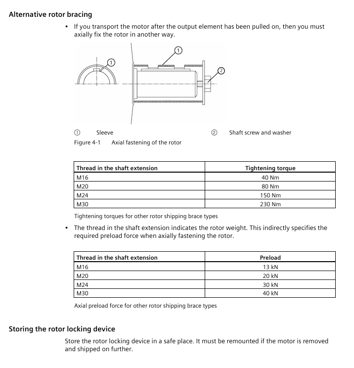
Rotor fixing: During transportation, rotor fixing components need to be installed, and vertically installed motors need to be stored in a vertical position.
2. Mechanical installation
General rules:
Bolt: Only use new bolts of grade 8.8 or above, with no oil/paint on the fixing surface and a surface roughness of Rz 10-40 μ m;
Tightening torque: M5=5Nm, M6=8Nm, M8=20Nm, M10=40Nm, optional Loctite 243 anti loosening.
Installation in different scenarios:
Horizontal foot installation (IM B3): Adjust the levelness with shims, with a support surface flatness of ≤ 0.2mm (shaft height ≥ 180);
Flange installation (IM B5): The flange centering surface is coated with paste, and the bolts are pre tightened in a 120 ° distribution, and finally tightened in diagonal order;
Vertical installation (IM V1): The rotor needs to be supported (to avoid bearing overload), and a protective cover should be added when the shaft end is facing downwards (to prevent foreign objects from falling in).
Alignment requirements:
Speed (rpm) Parallel deviation (mm) Angular deviation (mm/100mm Coupling diameter)
750 0.09 0.09
1500 0.06 0.05
3000 0.03 0.025
3. Electrical connection
Safety requirements:
Power supply: Only connect to the matching frequency converter or power grid, and do not directly connect to the three-phase AC power grid (frequency converter drives the motor);
Grounding: The PE wire is directly connected to the power module, and the grounding terminal inside the terminal box needs to be fastened with M5 bolts (torque 1.8-2.5Nm).
Specific connection:
Power cable: 4-core (PE=green yellow, U=black, V=black, W=black), core wire cross-section selected according to rated current (2.5mm ² corresponds to 21A, 16mm ² corresponds to 66A);
Control cable: The temperature sensor/anti condensation heating cable needs to be wired separately from the power cable, and the shielding layer should be grounded at one end;
Terminal marking: According to EN/IEC 60034-8, U/V/W corresponds to L1/L2/L3, and swapping any two phases can change the direction of rotation.
4. Debugging
Debugging premise:
Mechanical: Complete installation alignment, manually rotate the rotor without any obstruction;
Electrical: Insulation resistance ≥ 30M Ω, reliable PE grounding, cable gland tightened (M20 gland torque 12Nm).
Key steps:
No load test run: Power on and run for 5 minutes, check the steering (clockwise is U-V-W phase sequence) and vibration (≤ 4.5mm/s);
Load trial operation: gradually load to rated load, monitor current (≤ rated current), bearing temperature (≤ 115 ℃ alarm, ≤ 120 ℃ shutdown);
Variable frequency drive debugging: Parameterize the variable frequency drive (input motor rated current, speed, number of poles), set the avoidance frequency (38-48Hz, shaft height 315 two pole motor).
5. Operation and maintenance
Operation monitoring:
Normal parameters: current ≤ rated value, bearing temperature ≤ 90 ℃, vibration ≤ 4.5mm/s;
Troubleshooting: Motor cannot start (check for overload/phase loss), overheating (check for cooling/load), abnormal noise (check for bearings/alignment), please refer to the fault table for details.
Maintenance cycle:
Maintain project cycle content
Initial inspection: 500 operating hours/6 months. Check bolt tightness, bearing temperature, and insulation resistance
Regularly inspect 16000 operating hours/2 years, clean the cooling air duct, grease (with oil nozzle bearings), and check the grounding
Bearing replacement: 50000 operating hours (horizontal)/20000 hours (vertical). Replace bearings and shaft seals, clean the bearing chamber
Insulation testing measures insulation resistance (≥ 30M Ω) and polarization index (≥ 2) every year/after shutdown for more than 3 months
6. Scrapping and disposal
Scrap steps:
Power off → wait for capacitor discharge → cool down for 30 minutes;
Dismantle the cable and drain the coolant (compliant treatment);
Remove the fixing bolts of the motor and disassemble it in reverse order (first remove the fan cover, then remove the end cover).
Waste disposal:
Metal components: classified recycling of steel, aluminum, and copper (winding copper can be melted and recycled);
Insulation material: incineration (in compliance with environmental requirements);
Hazardous substance: Lead (CAS 7439-92-1, content ≤ 0.1%) must be disposed of in accordance with the REACH directive, and packaging materials (PE/PP) are recyclable.
Appendix and Compliance
1. Key Appendix Resources
Spare parts list: including end caps (1.40), bearings (1.60), cable glass (5.03), fans (7.04) and other spare parts models and explosion diagrams;
Tightening torque table: specify the tightening torque for different thread specifications (such as M12 bolt 70Nm, M16 cable glass 170Nm);
Terminal box dimensions: Axis height 71-90 Terminal box TB7 D04 (dimensions A=89mm, B=111mm), Axis height 250-280 Terminal box TB1 NO1 (dimensions A=233mm, B=319mm).
2. Compliance standards
Following standards: EN/IEC 60034 (Rotating Electrical Machinery), EN/IEC 60204-1 (Mechanical and Electrical Equipment), EMC 2014/30/EU (Electromagnetic Compatibility);
Environmental directives: RoHS (Restriction of Hazardous Substances), REACH (Control of Substances of Very High Concern, such as Lead Content ≤ 0.1%)
- OMRON
- ABB
- General Electric
- EMERSON
- Honeywell
- HIMA
- ALSTOM
- Rolls-Royce
- MOTOROLA
- Rockwell
- Siemens
- Woodward
- YOKOGAWA
- FOXBORO
- KOLLMORGEN
- MOOG
- KB
- YAMAHA
- BENDER
- TEKTRONIX
- Westinghouse
- AMAT
- AB
- XYCOM
- Yaskawa
- B&R
- Schneider
- KONGSBERG
- NI
- WATLOW
- ProSoft
- SEW
- ADVANCED
- Reliance
- TRICONEX
- METSO
- MAN
- Advantest
- STUDER
- DANAHER MOTION
- Bently
- Galil
- EATON
- MOLEX
- DEIF
- B&W
- ZYGO
- Aerotech
- DANFOSS
- Beijer
- Moxa
- Rexroth
- Johnson
- WAGO
- TOSHIBA
- BMCM
- SMC
- HITACHI
- HIRSCHMANN
- Application field
- XP POWER
- CTI
- TRICON
- STOBER
- Thinklogical
- Horner Automation
- Meggitt
- Fanuc
- Baldor
- SHINKAWA
- Other Brands
- UniOP
- KUKA
- Iba
- Beckhoff
- ADLINK
-
 Beckwith M-0145 First Customer Protector
 -
 Beckwith M-0170A AC Current Relay
 -
 Beckwith PRIDE M-0296C 3 Phase Programmable Relay
 -
 Beckwith Pride M-0296b 3-Phase Programmable Relay
 -
Beckwith M-0245C High Speed Sync-Check Relay Guide
-
 Beckwith M-0115A AC Parallel Balancing Module
 -
 Beckwith M-0389 Voltage Verifier Relay
 -
Beckwith M-0115A Parallel Balancing Module
-
Beckwith M-0389 Voltage Verifier
-
 Beckwith PRIDE M-0420 Multifunction Relay Protection Module 48VDC
 -
 Beckwith Electric M-3430 Generator Protection Relay
 -
 Beckwith Electric M-0067E Tapchanger Control
 -
Beckwith Electric M-0420 Multifunction Relay
-
 Beckwith Electric M-2001D-6L4S20C0S0X Tap Changer Control
 -
 Beckwith Electric M3425A-STD1 Generator Protection Relay
 -
 Beckwith Electric M-0245C High Speed Sync-Check Relay
 -
Beckwith Electric M-3520 Intertie Protection Relay Guide
-
Beckwith Electric M-2001C-6SL Tap Changer Control
-
 Beckwith Electric M-2001C Tap Changer Control Guide
 -
Beckwith 35-12-635 Generator Protection Keypad Interface
-
 Beckwith Electric P-2216 Generator Protection Main Board
 -
 Beckwith Electric M-2293 Tap Changer Control Guide
 -
 Beckwith M-4272-6AB1EH0 Integrated Synchronizing Motor Bus Transfer
 -
Beckwith Electric M-4272 Motor Bus Transfer 60-140V 50/60Hz
-
Beckwith Electric M-2001B TapChanger Control
-
 Beckwith Electric M-0193B Synchrocloser Unit
 -
Beckwith Electric M-0115A AC Parallel Balancing Module
-
Beckwith Electric M-0169A Current Transformer
-
Beckwith Electric P-1939 Generator Protection Annunciator Panel
-
Beckwith Electric M-3311A Transformer Protection Relay Guide
-
Beckwith Electric M-0245B High Speed Sync-Check Relay
-
Beckwith Electric M3420 Generator Protection Relay
-
 Beckwith M-0193B Syncrocloser Unit
 -
 Beckwith Electric M-520 Intertie Protection Relay
 -
 Beckwith Electric M-3425A Generator Protection Relay
 -
Beckwith M-3425 Integrated Generator Protection Relay
-
Beckwith M-0115A Parallel Balancing Module
-
Beckwith Electric M-4272 Integrated Synchronizing Motor Bus Transfer
-
Beckwith Electric M-3420 Generator Protection System
-
Beckwith M-0193 Syncrocloser Unit
-
 Basler Electric DECS-250-CN1SN1N Digital Excitation Control System
 -
 Basler Electric BE1-700 E0N2X1N Digital Protective Relay
 -
 Basler Electric SR4A-2B15B3A Static Voltage Regulator 120VAC 50/60Hz
 -
 Basler Electric 9261402111 PCB Control Board 9346000033
 -
 Basler Electric BE28053-002 Transformer BE28053002
 -
 Basler Electric BE3-25A Auto Synchronizer B1D Sync Module
 -
 Basler Electric BE3-GPR Generator Protective Relay
 -
 Basler Electric SCP-250-G-60 VAR Power Factor Controller 9 1100 00 109
 -
 Basler Electric BE3-32-1S1N1 Reverse Power Relay 277V 5A
 -
 Basler Electric ACA1300-60GM Area Scan Camera 106200-17
 -
 Basler Electric UFOV 260 A Protection Module Specs
 -
 Basler Electric BE03303001 Control Module
 -
Basler Electric BE3-GPR-P1BVSF Generator Protective Relay
-
 Basler Electric BE1-87G Solid State Protective Relay Guide
 -
 BASLER ELECTRIC BE1-60 VOLTAGE BALANCE RELAY T176884
 -
 Basler Electric BE1-32R Protective Relay
 -
 Basler Electric 9022900-103 Transformer 6-7VA 60Hz
 -
 Basler Electric BE1-59-A4E-E1K-B1S3F Overvoltage Relay
 -
 Basler Electric KR2FF-M Voltage Regulator 9 1163 00 103
 -
 Basler Electric UFOV 260 A Protective Module
 -
 Basler Electric PCB Assembly 9059701100 919620
 -
 Basler Electric SR8A2B01A3E Static Voltage Regulator
 -
 Basler Electric SSR125-12 Static Voltage Regulator 9185900102
 -
 Basler Electric SSR 63-12 Static Voltage Regulator 600VAC
 -
 Basler Electric BE1-60 Solid State Protective Relay
 -
 Basler Electric BE3-47N/27-3A4N2 Voltage Relay 9320400101
 -
 Basler Electric BE1-59 Over Voltage Relay
 -
 Basler Electric DECS100-B15 Automatic Voltage Regulator
 -
 Basler Electric PRS250 Veri-Sync Relay 9088800102
 -
Basler Electric BE25927001 Current Transformer 1:34 Amp
-
Basler Electric 9170818100 Generator Differential Relay
-
 Basler Electric BE1-59N Solid State Ground Fault Overvoltage Relay
 -
 Basler Electric 1783 DC Current Transformer Coil 1200:5A
 -
Basler Electric BE1-67 Ground Directional Overcurrent Relay
-
 Basler Electric UFOV-260A Underfrequency Overvoltage Module
 -
 Basler Electric BE10493001 Control Module
 -
Basler Electric SSR125-12 Static Voltage Regulator Guide
-
 Basler Electric BE1810/U-2 Solid State Frequency Relay Guide
 -
 Basler Electric 9105100106 UFOV-250A Protector Guide
 -
 Basler Electric MOC2199 9072300-335 Relay Module Guide
 -
 Basler Electric 9289902106 Circuit Board
 -
Basler Electric BE1-32R Protective Relay A1E E1P BOS1P
-
 Basler Electric RAL6144-16GM GigE Line Scan Camera with Lens
 -
 Basler Electric BE3-49R-5I5A1 Temperature Relay
 -
 Basler Electric BE1-32R Power Relay B3E E1R A0N1F
 -
 Basler Electric SR4A2B06B3A Static Voltage Regulator Features
 -
 Basler Electric 9121000106 Manual Voltage Control MVC Guide
 -
Basler Electric SR32A-2B15B3E Static Voltage Regulator
-
 Basler Electric SR4A2B06B3A Static Voltage Regulator Guide
 -
Basler Electric 801A193F02 Hammond Transformer Module
-
 Basler Electric BE1-24 Volts Per Hertz Relay A1E F1J D1S0F
 -
 Basler Electric AEC63-7 Analog Excitation Controller 220-277V
 -
Basler Electric BE132R Power Relay T245579
-
 Basler Electric MVC 108 Manual Voltage Control 90 37000 102
 -
 Basler Electric 9022900-103 Control Transformer 6-7VA 60Hz
 -
 Basler Electric BE1-79M Plug Adapter 9170111102
 -
 Basler Electric 9 2007 00 100 Current Boost System CBS 305
 -
 Basler Electric SR4A2B01B3A Static Voltage Regulator 120V
 -
Basler Electric BE1-32R Power Solid State Relay E2E A10 A0N0F
-
Basler Electric PRS250 Veri-Sync Relay 9088800102
-
 Basler DECS 125-15-B2C Digital Excitation Control
 -
 Basler BE 13693 002 Transformer
 -
Basler BE1-59N Ground Fault Overvoltage Relay
-
 Basler BE1-79A Reclosing Relay
 -
Basler 9-1051-00-105 Overload Protection Module
-
 Basler BE1-32R Power Relay – Directional Overcurrent Guide
 -
 Basler 9319700103 BE3-27T/59T-3A1N3 Voltage Relay
 -
Basler BE1-87G Generator Differential Relay
-
 Basler BE3-25-1D1N4 9319100106 480V Relay
 -
 Basler SR8A2B07B3A Static Voltage Regulator
 -
 Basler Electric BE4-27/59 Over/Under Voltage Relay 307-2552
 -
Basler Electric SR32A2B05B3E Static Voltage Regulator
-
Basler Electric BE1-27 A3E C3J A1N6F Solid State Protective Relay
-
 Basler Electric 9174700-100 Excitation Limiter Generator
 -
Basler Electric BE1-87G Generator Differential Relay 09833
-
 Basler Electric 9310200100 Power Supply Module
 -
 Basler Electric TIEE1CD0N07 Control Module
 -
Basler Electric BE1-59N Ground Fault Relay T214750
-
Basler Electric SR8A2B10B3AX Static Voltage Regulator 9060200126
-
 Basler Electric SSR 125-12 Voltage Regulator
 -
 Rolls Royce H1111.0204 Ship Main Controller
 -
 Basler Electric BE3-32-3AC Reverse Power Relay 9 1376 00 105
 -
Basler Electric BE3-25-1A1N4 Synch Check Relay 9319100100
-
 Basler Electric SR4A-2B15B3A Static Voltage Regulator
 -
 Basler Electric SR4A-2B15B3E Static Voltage Regulator
 -
 Basler Electric 9170818100 Solid State Protective Relay
 -
 Basler Electric AEC63-7 Analog Excitation Controller
 -
Basler Electric 17483 Auxiliary Module


