
SIEMENS QFM31xx series air duct sensor
SIEMENS QFM31xx series air duct sensor
Product basic information
1. Product model
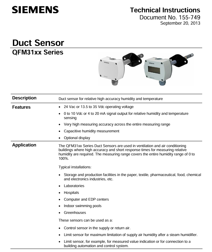
Covering sub models such as QFM3100 (basic version), QFM3160 (with display), QFM3171D (4-20mA output), etc., collectively referred to as the QFM31xx series, it provides high-precision measurement of air duct temperature and humidity.
2. Application scenarios
Sensors are suitable for ventilation and air conditioning systems with high requirements for temperature and humidity accuracy and response speed. Typical installation scenarios include:
Industrial scenarios: storage and production workshops in paper mills, textile factories, pharmaceutical factories, food factories, and electronic factories;
Special venues: laboratories, hospitals, computer data centers, indoor swimming pools, greenhouses;
Functional roles: Air supply/return control sensor, humidity limit sensor after steam humidifier, building automation system (BAS) access sensor.
Core technical characteristics of the product
1. Power supply and signal output
Category parameter content, key data
Supply voltage AC/DC dual compatible 24 Vac (± 20%, 50/60Hz); 13.5-35 Vdc
Low power consumption design<1 VA
Humidity output with two signal types: 0-10 Vdc (corresponding to 0-100% RH, maximum current 1mA); 4-20 mA (corresponding to 0-100% RH)
The temperature output range can be selected from 0-10 Vdc/4-20 mA, and the range can be selected through jumper wires (see Table 2)
Cable lengths are classified by wire diameter as 24 AWG (50m), 18 AWG (150m), and 16 AWG (300m)
2. Measurement performance (accuracy and response)
Measurement Type Accuracy Index Response Characteristics Remarks
± 2% RH at relative humidity of 23 ℃; temperature coefficient<0.05% RH/℃ Time constant of about 20s (in flowing air) Effective measurement range 0-95% RH (0-9.5V/4-19.2mA linear)
± 0.8 ℃ at a temperature of 15-35 ℃; -The time constant of ± 1.0 ℃ at 40-15 ℃/35-70 ℃ is about 20 seconds (in flowing air). The sensing element is NTC 10K Ω
3. Protection and environmental adaptability
Protection level: IP65 (NEMA 4), dustproof and water-resistant, suitable for humid air duct environments;
Work environment: Adapt to the air temperature inside the duct (consistent with the selected temperature range), humidity 0-100% RH;
Material compatibility: The shell is made of polycarbonate (impact resistant), the filter cap is made of the same material, and the overall silicon free design avoids polluting sensitive environments (such as electronic factories).
Mechanical Design and Installation Specification
1. Mechanical structure
Overall composition: consisting of a housing (base+detachable cover plate), a printed circuit board (PCB), wiring terminals, mounting flanges, and an immersion probe (including sensing elements and filter caps);
Shell design:
Base: Integrated wiring terminal and conduit clamping system (fixing flexible conduit), color RAL 7001 (silver gray);
Cover plate: Built in measurement circuit and jumper (range configuration), color RAL 7035 (light gray), fixed with screws;
Probe: Made of polycarbonate material (RAL 7001), the end sensing element is protected by a filter cap to prevent dust contamination.
2. Installation method and requirements
Key requirements for installation method and operation steps
Install flange (recommended) 1. Assemble the flange with the sensor; 2. Fix the flange to the air duct according to the required immersion length; 3. Insert the sensor and tighten it to adjust the immersion length as needed. The flange material is PA66 (black)
No installation flange 1. Use 4 mounting holes on the shell; 2. Directly screw the sensor onto the air duct using the maximum immersion length to ensure measurement representativeness
Special scenario (dew point offset) 1. Only fix the flange to the air duct wall; 2. Insert the sensor from the flange and clamp it tightly. It must be installed in the return air duct to avoid measurement deviation
Installation taboos:
Avoid probe impact: Sensing components are easily damaged by impact and should be handled gently during installation;
Distance between steam humidifiers: The minimum distance from the humidifier should be ≥ 3m (recommended ≤ 10m) to prevent sudden humidity changes from affecting accuracy;
Sealing protection: It is forbidden to remove the seal between the shell and the cover plate to prevent water vapor from entering and damaging the circuit.
Parameter configuration and debugging
1. Jumper configuration (on PCB, under cover)
The jumper has 6 pins and 1 jumper cap, which is used to select temperature range, display unit, and activate testing functions. The specific configuration is as follows:
Configure the parameters corresponding to the jumper position of the configuration function
Temperature range selection left (1) -31 ° F~95 ° F (-35 ℃~35 ℃)
Right position (3) -40 ° F~158 ° F (-40 ℃~70 ℃)
Display unit selection (with LCD model) vertical right position Celsius (℃, factory default)
Vertical left Fahrenheit (℉)
Test function activation level signal output specific values (such as 0V/10V, 4mA/20mA) for troubleshooting
2. Debugging steps
Wiring inspection: Confirm that the power and signal lines are connected correctly (refer to the terminal definition in Figure 2-6, for example, QFM3171 needs to ensure that G1/I1 is powered on, even if only temperature output is used);
- OMRON
- ABB
- General Electric
- EMERSON
- Honeywell
- HIMA
- ALSTOM
- Rolls-Royce
- MOTOROLA
- Rockwell
- Siemens
- Woodward
- YOKOGAWA
- FOXBORO
- KOLLMORGEN
- MOOG
- KB
- YAMAHA
- BENDER
- TEKTRONIX
- Westinghouse
- AMAT
- AB
- XYCOM
- Yaskawa
- B&R
- Schneider
- KONGSBERG
- NI
- WATLOW
- ProSoft
- SEW
- ADVANCED
- Reliance
- TRICONEX
- METSO
- MAN
- Advantest
- STUDER
- DANAHER MOTION
- Bently
- Galil
- EATON
- MOLEX
- DEIF
- B&W
- ZYGO
- Aerotech
- DANFOSS
- Beijer
- Moxa
- Rexroth
- Johnson
- WAGO
- TOSHIBA
- BMCM
- SMC
- HITACHI
- HIRSCHMANN
- Application field
- XP POWER
- CTI
- TRICON
- STOBER
- Thinklogical
- Horner Automation
- Meggitt
- Fanuc
- Baldor
- SHINKAWA
- Other Brands
- UniOP
- KUKA
- Iba
- Beckhoff
- ADLINK
-
 Beckwith M-0145 First Customer Protector
 -
 Beckwith M-0170A AC Current Relay
 -
 Beckwith PRIDE M-0296C 3 Phase Programmable Relay
 -
 Beckwith Pride M-0296b 3-Phase Programmable Relay
 -
Beckwith M-0245C High Speed Sync-Check Relay Guide
-
 Beckwith M-0115A AC Parallel Balancing Module
 -
 Beckwith M-0389 Voltage Verifier Relay
 -
Beckwith M-0115A Parallel Balancing Module
-
Beckwith M-0389 Voltage Verifier
-
 Beckwith PRIDE M-0420 Multifunction Relay Protection Module 48VDC
 -
 Beckwith Electric M-3430 Generator Protection Relay
 -
 Beckwith Electric M-0067E Tapchanger Control
 -
Beckwith Electric M-0420 Multifunction Relay
-
 Beckwith Electric M-2001D-6L4S20C0S0X Tap Changer Control
 -
 Beckwith Electric M3425A-STD1 Generator Protection Relay
 -
 Beckwith Electric M-0245C High Speed Sync-Check Relay
 -
Beckwith Electric M-3520 Intertie Protection Relay Guide
-
Beckwith Electric M-2001C-6SL Tap Changer Control
-
 Beckwith Electric M-2001C Tap Changer Control Guide
 -
Beckwith 35-12-635 Generator Protection Keypad Interface
-
 Beckwith Electric P-2216 Generator Protection Main Board
 -
 Beckwith Electric M-2293 Tap Changer Control Guide
 -
 Beckwith M-4272-6AB1EH0 Integrated Synchronizing Motor Bus Transfer
 -
Beckwith Electric M-4272 Motor Bus Transfer 60-140V 50/60Hz
-
Beckwith Electric M-2001B TapChanger Control
-
 Beckwith Electric M-0193B Synchrocloser Unit
 -
Beckwith Electric M-0115A AC Parallel Balancing Module
-
Beckwith Electric M-0169A Current Transformer
-
Beckwith Electric P-1939 Generator Protection Annunciator Panel
-
Beckwith Electric M-3311A Transformer Protection Relay Guide
-
Beckwith Electric M-0245B High Speed Sync-Check Relay
-
Beckwith Electric M3420 Generator Protection Relay
-
 Beckwith M-0193B Syncrocloser Unit
 -
 Beckwith Electric M-520 Intertie Protection Relay
 -
 Beckwith Electric M-3425A Generator Protection Relay
 -
Beckwith M-3425 Integrated Generator Protection Relay
-
Beckwith M-0115A Parallel Balancing Module
-
Beckwith Electric M-4272 Integrated Synchronizing Motor Bus Transfer
-
Beckwith Electric M-3420 Generator Protection System
-
Beckwith M-0193 Syncrocloser Unit
-
 Basler Electric DECS-250-CN1SN1N Digital Excitation Control System
 -
 Basler Electric BE1-700 E0N2X1N Digital Protective Relay
 -
 Basler Electric SR4A-2B15B3A Static Voltage Regulator 120VAC 50/60Hz
 -
 Basler Electric 9261402111 PCB Control Board 9346000033
 -
 Basler Electric BE28053-002 Transformer BE28053002
 -
 Basler Electric BE3-25A Auto Synchronizer B1D Sync Module
 -
 Basler Electric BE3-GPR Generator Protective Relay
 -
 Basler Electric SCP-250-G-60 VAR Power Factor Controller 9 1100 00 109
 -
 Basler Electric BE3-32-1S1N1 Reverse Power Relay 277V 5A
 -
 Basler Electric ACA1300-60GM Area Scan Camera 106200-17
 -
 Basler Electric UFOV 260 A Protection Module Specs
 -
 Basler Electric BE03303001 Control Module
 -
Basler Electric BE3-GPR-P1BVSF Generator Protective Relay
-
 Basler Electric BE1-87G Solid State Protective Relay Guide
 -
 BASLER ELECTRIC BE1-60 VOLTAGE BALANCE RELAY T176884
 -
 Basler Electric BE1-32R Protective Relay
 -
 Basler Electric 9022900-103 Transformer 6-7VA 60Hz
 -
 Basler Electric BE1-59-A4E-E1K-B1S3F Overvoltage Relay
 -
 Basler Electric KR2FF-M Voltage Regulator 9 1163 00 103
 -
 Basler Electric UFOV 260 A Protective Module
 -
 Basler Electric PCB Assembly 9059701100 919620
 -
 Basler Electric SR8A2B01A3E Static Voltage Regulator
 -
 Basler Electric SSR125-12 Static Voltage Regulator 9185900102
 -
 Basler Electric SSR 63-12 Static Voltage Regulator 600VAC
 -
 Basler Electric BE1-60 Solid State Protective Relay
 -
 Basler Electric BE3-47N/27-3A4N2 Voltage Relay 9320400101
 -
 Basler Electric BE1-59 Over Voltage Relay
 -
 Basler Electric DECS100-B15 Automatic Voltage Regulator
 -
 Basler Electric PRS250 Veri-Sync Relay 9088800102
 -
Basler Electric BE25927001 Current Transformer 1:34 Amp
-
Basler Electric 9170818100 Generator Differential Relay
-
 Basler Electric BE1-59N Solid State Ground Fault Overvoltage Relay
 -
 Basler Electric 1783 DC Current Transformer Coil 1200:5A
 -
Basler Electric BE1-67 Ground Directional Overcurrent Relay
-
 Basler Electric UFOV-260A Underfrequency Overvoltage Module
 -
 Basler Electric BE10493001 Control Module
 -
Basler Electric SSR125-12 Static Voltage Regulator Guide
-
 Basler Electric BE1810/U-2 Solid State Frequency Relay Guide
 -
 Basler Electric 9105100106 UFOV-250A Protector Guide
 -
 Basler Electric MOC2199 9072300-335 Relay Module Guide
 -
 Basler Electric 9289902106 Circuit Board
 -
Basler Electric BE1-32R Protective Relay A1E E1P BOS1P
-
 Basler Electric RAL6144-16GM GigE Line Scan Camera with Lens
 -
 Basler Electric BE3-49R-5I5A1 Temperature Relay
 -
 Basler Electric BE1-32R Power Relay B3E E1R A0N1F
 -
 Basler Electric SR4A2B06B3A Static Voltage Regulator Features
 -
 Basler Electric 9121000106 Manual Voltage Control MVC Guide
 -
Basler Electric SR32A-2B15B3E Static Voltage Regulator
-
 Basler Electric SR4A2B06B3A Static Voltage Regulator Guide
 -
Basler Electric 801A193F02 Hammond Transformer Module
-
 Basler Electric BE1-24 Volts Per Hertz Relay A1E F1J D1S0F
 -
 Basler Electric AEC63-7 Analog Excitation Controller 220-277V
 -
Basler Electric BE132R Power Relay T245579
-
 Basler Electric MVC 108 Manual Voltage Control 90 37000 102
 -
 Basler Electric 9022900-103 Control Transformer 6-7VA 60Hz
 -
 Basler Electric BE1-79M Plug Adapter 9170111102
 -
 Basler Electric 9 2007 00 100 Current Boost System CBS 305
 -
 Basler Electric SR4A2B01B3A Static Voltage Regulator 120V
 -
Basler Electric BE1-32R Power Solid State Relay E2E A10 A0N0F
-
Basler Electric PRS250 Veri-Sync Relay 9088800102
-
 Basler DECS 125-15-B2C Digital Excitation Control
 -
 Basler BE 13693 002 Transformer
 -
Basler BE1-59N Ground Fault Overvoltage Relay
-
 Basler BE1-79A Reclosing Relay
 -
Basler 9-1051-00-105 Overload Protection Module
-
 Basler BE1-32R Power Relay – Directional Overcurrent Guide
 -
 Basler 9319700103 BE3-27T/59T-3A1N3 Voltage Relay
 -
Basler BE1-87G Generator Differential Relay
-
 Basler BE3-25-1D1N4 9319100106 480V Relay
 -
 Basler SR8A2B07B3A Static Voltage Regulator
 -
 Basler Electric BE4-27/59 Over/Under Voltage Relay 307-2552
 -
Basler Electric SR32A2B05B3E Static Voltage Regulator
-
Basler Electric BE1-27 A3E C3J A1N6F Solid State Protective Relay
-
 Basler Electric 9174700-100 Excitation Limiter Generator
 -
Basler Electric BE1-87G Generator Differential Relay 09833
-
 Basler Electric 9310200100 Power Supply Module
 -
 Basler Electric TIEE1CD0N07 Control Module
 -
Basler Electric BE1-59N Ground Fault Relay T214750
-
Basler Electric SR8A2B10B3AX Static Voltage Regulator 9060200126
-
 Basler Electric SSR 125-12 Voltage Regulator
 -
 Rolls Royce H1111.0204 Ship Main Controller
 -
 Basler Electric BE3-32-3AC Reverse Power Relay 9 1376 00 105
 -
Basler Electric BE3-25-1A1N4 Synch Check Relay 9319100100
-
 Basler Electric SR4A-2B15B3A Static Voltage Regulator
 -
 Basler Electric SR4A-2B15B3E Static Voltage Regulator
 -
 Basler Electric 9170818100 Solid State Protective Relay
 -
 Basler Electric AEC63-7 Analog Excitation Controller
 -
Basler Electric 17483 Auxiliary Module


