
SIEMIENS SIPART PS2 (6DR5...) Electrical Positioner Operation Guide
SIEMIENS SIPART PS2 (6DR5...) Electrical Positioner Operation Guide
Basic and Product Overview
Overview
The compact operation guide for SIPART PS2 (6DR5...) electric pneumatic positioner covers core contents such as product introduction, safety instructions, installation and mounting, connection, debugging, maintenance, technical parameters, and appendices. It is clear that the positioner is suitable for continuous control of process valves in multiple industries such as chemical, oil and gas, and energy. It emphasizes that the use in hazardous areas must comply with explosion-proof standards (such as ATEX, IECEx), and installation and debugging must follow specific steps (such as automatic/manual initialization). At the same time, detailed technical data (such as working temperature -30~+80 ° C, protection level IP66) and adaptation information for each module (alarm, position feedback, etc.) are provided to ensure safe and compliant operation of the equipment.
Product Usage and Compatibility
Usage: Used in 8 major industries including chemical, oil and gas, energy, food and beverage, papermaking, water supply and drainage, pharmaceuticals, and offshore platforms to achieve continuous control of valves in pneumatic drive processes
Compatibility: Different document versions need to match specific device firmware (FW) and integrated software versions, as shown in the table below:
Communication protocol document version, device firmware requirements, compatible with integrated software (including EDD version)
HART 05/2018 FW: 5.01.00 and above; Device version 6 and above SIMATIC PDM V9.0(EDD:23.00.00+)、AMS Device Manager V12.5(EDD:23.00.00+) wait
PROFIBUS PA 05/2018 FW: 6.00.00 and above SIMATIC PDM V9.0 (EDD: 22.00.00+), SITRANS DTM V4.1 (EDD: 22.00.01+), etc
FOUNDATION Fieldbus 05/2018 FW: 3.00.00 and above; Device version 3 SITRANS DTM V4.1(EDD:3.00.00+)、AMS Device Manager V12.5(EDD:3.00.00+) wait
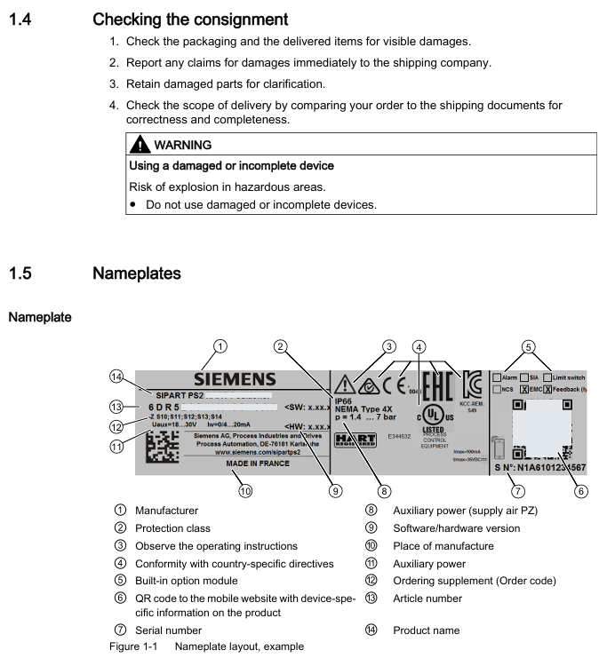
Goods inspection and nameplate
Goods inspection: After receiving the goods, it is necessary to check whether the packaging/items are damaged and verify the consistency between the order and the shipping documents; Prohibit the use of damaged or incomplete equipment (there is a risk of explosion in hazardous areas)
Nameplate information: including key information such as manufacturer, protection level (e.g. IP66), software and hardware versions, explosion-proof identification (e.g. Ex d IIC T6/T4), serial number, etc. The explosion-proof nameplate needs to be additionally labeled with ATEX/IECEx/FM/CSA certification information
Safety instructions (core risk prevention and control)
Warning level system
DANGER: Failure to take preventive measures may result in death or serious personal injury
Warning: Failure to take preventive measures may result in death or serious personal injury
CAUTION: Failure to take preventive measures may result in minor personal injury
NOTICE: Failure to take preventive measures may result in property damage
Requirements for use in hazardous areas
Operator: Must have the qualification to operate equipment in hazardous areas and be familiar with electrical, high-voltage, and hazardous medium safety regulations
Explosion proof requirements: Only use equipment labeled with the corresponding explosion-proof level (such as II 2 G Ex d IIC T6/T4 Gb), and prohibit the use of equipment suitable for non hazardous areas; If the equipment has been used in non hazardous areas, its explosion-proof label must be permanently removed
Special Warning: The pneumatic terminal board of 6DR5. 6 locator is a safety component of explosion-proof shell, and its fixing screws must not be loosened
Other safety regulations
Equipment modification: Only modifications are allowed according to the document instructions. Unauthorized modifications will cancel the warranty and certification
Power requirements: It is necessary to connect a safety isolated Extra Low Voltage (SELV) to avoid voltage flashover; Dangerous area connection equipment must be carried out in a power-off state (except for Ex i version)
Cable requirements: Use cable glands/plugs that meet explosion-proof standards. Unused cable entrances must be sealed, and shielded cables are only allowed to be grounded at one end (when crossing hazardous areas)
Installation and mounting
Basic security prerequisites
Pneumatic actuators have high operating force and must follow their safety instructions; The mounting kit with position detection lever poses a risk of compression, and it is prohibited to insert limbs into the range of motion of the lever
Only use Siemens original accessories/spare parts to avoid the risk of explosion in hazardous areas; Before installation, confirm that there is no visible damage to the equipment and that the sealing gasket is correctly positioned to avoid damage during cover installation
Different mounting methods for actuators
Linear actuator: Use 6DR4004-8V mounting kit, suitable for stroke 3-35mm; for stroke exceeding 35mm, an additional 6DR4004-8L lever needs to be ordered
Angular stroke actuator: VDI/VDE 3845 mounting surface (thickness>4mm with reinforcement) needs to be provided on the actuator side, paired with 6DR4004-8D kit or TGX: 16300-1556 stainless steel coupling
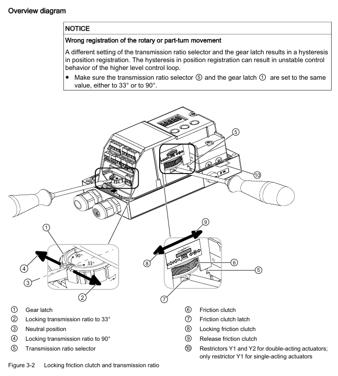
Vibration/acceleration environment treatment
The equipment is equipped with a friction clutch and a gear lock with a transmission ratio selector to cope with strong vibrations/accelerations (such as emergency shut-off valves, steam shock scenarios)
Locking steps: Ensure that the gear lock is in the neutral position → Confirm the gear ratio selector (33 ° or 90 °) → Lock the gear lock with a 4mm screwdriver → Secure the friction clutch (non explosion proof shell version), ensuring that the gear ratio selector is set to the same position as the gear lock (to avoid position detection delay)
Optional module installation
Optional modules for standard/intrinsic safety versions: position feedback module, alarm module, SIA module, mechanical limit switch module, EMC filtering module, NCS sensor, internal NCS module
Optional modules for explosion-proof shell version: only supports position feedback module, alarm module, and internal NCS module; The internal NCS module is used for wear free position detection and is installed in the same slot as the position feedback module
Connection (electrical and pneumatic)
electrical connection
Basic requirement: When the environmental temperature difference exceeds 20 ° C, it should be left to stand for several hours before being powered on (to avoid condensation); When the ambient temperature is ≥ 60 ° C, cables with a temperature resistance of ≥ 80 ° C must be used; The 2-wire version prohibits connecting the voltage source to the current input terminal (I2w, terminals 6/7) and requires the use of a high impedance power supply
Wiring for different communication versions:
With/without HART: Supports 2/3/4 wire system, 2-wire current input 4-20mA (terminals 6+, 7-)
PROFIBUS PA: Bus circuit connection terminals 6/7, equipped with safety shutdown input (terminals 81+, 82-)
FOUNDATION Fieldbus: Bus circuit connection terminals 6/7, supporting simulation enable function
M12 connector adaptation: The M12 pins of different modules correspond to different functions, such as the 61+pin 1 (brown) and 62- pin 3 (blue) of the position feedback module 6DR4004-6J/8J
Pneumatic connection
Interface specifications: All are G ¼ or ¼ "NPT internal threads, Y1 is the driving pressure for single/double acting actuators 1, Y2 is the driving pressure for double acting actuators 2
Interface positions for different models:
6DR5. 0/1/2/3: The pneumatic interface is located on the right side of the locator, including Y1, Y2, air source PZ, and exhaust port with muffler
6DR5. 5/6 (Explosion proof enclosure): The pneumatic interface is on the right side, including Y1/Y2 flow restrictor, enclosure ventilation port, and exhaust port
Safe location settings:
When power is off: single acting actuator Y1 releases pressure; Double acting actuator Y1 applies pressure (maximum driving pressure) and Y2 releases pressure; Fail in Place actuator maintains the current pressure of Y1/Y2
Usage of flow restrictor: When the actuator travel time T>1.5s, rotate the Y1/Y2 flow restrictor clockwise to reduce the air output. It is recommended to close it first and then slowly open it. The double acting valve should ensure that the two flow restrictors are set close to each other
Debugging (Commissioning)
Basic safety precautions
Installation and connection must be completed before debugging in hazardous areas, and equipment must be turned off (except for Ex i version); If there may be water in the compressed air pipeline, the purge air selector should be set to "OUT" (then set to "IN" after drainage)
Special requirements for natural gas operation: Only intrinsically safe (Ex ia) equipment can be used; Prohibited from operating in enclosed spaces; Adequate ventilation is required (see technical data for maximum ventilation capacity); Prohibit the use of mechanical limit switch modules; Relieve pressure for at least 2 minutes before maintenance
Initialization type and process
Initialization type:
Automatic initialization: Automatically detect the direction of action, actuator stroke/rotation angle, stroke time, and adapt control parameters, with a time consumption of ≤ 15 minutes
Manual initialization: manually set stroke/rotation angle, and automatically detect other parameters (applicable to PTFE lined valves)
Data replication: Copy the initialization data of the original device when replacing it to avoid process interruption
Core parameters (1-5):
Parameter function applicable to actuators, optional parameter value units
1. YFCT action direction/detection type linear/angular stroke linear: WAY/- WAY/FWAY/- FWAY/LWAY; Angular travel: turn/- turn; NCS adaptation: ncSt/ncSL/ncSLL, etc-
2. YAGL locator shaft rated rotation angle stroke 33, 90 degrees
3. YWAY travel range (optional) Linear (WAY/- WAY/ncSLL/- ncLL) OFF, 5, 10, 15, 20 (33 ° short lever); 25, 30, 35 (90 ° short leverage); 40~130 (90 ° long lever) mm
4. InitiatA automatically initializes all NOINI (uninitialized) and Strt (start)-
5. InitiatM manually initializes all NOINI (uninitialized) and Strt (start)-
Automatic initialization steps for linear actuators:
Press and hold the button for 5 seconds to enter configuration mode → Call 2. YAGL to confirm consistency with the transmission ratio selector → Set 3. YWAY (optional) → Call 4. InitiatA and press and hold for 5 seconds to start → Display "FINSH" after completion
Automatic initialization of angular actuator: Similar to linear actuator, default 2. YAGL=90 °, and display the total rotation angle after initialization
Maintenance and upkeep
Basic security requirements
Only authorized personnel from Siemens are authorized to perform repairs; The surface area of equipment in hazardous areas with dust exceeding 5mm needs to be cleaned (to avoid overheating); When cleaning, use a damp cloth or neutral cleaner, and do not use solvents such as acetone (to avoid damaging the plastic/paint surface)
After maintenance, it is necessary to correctly connect the equipment and close the casing to ensure the explosion-proof level; Button lock only allows authorized personnel to cancel (to avoid parameter errors affecting process safety)
Filter cleaning (core maintenance item)
Cleaning methods for different shell materials:
Polycarbonate (6DR5. 0), Aluminum Shell (6DR5. 3), Explosion proof Aluminum Shell (6DR5. 5): Disconnect the air source → Remove the pipeline → Open the cover → Unscrew the 3 screws of the pneumatic terminal board → Remove the filter screen/O-ring → Clean with compressed air → Reinstall in the original order (polycarbonate shell screws are self tapping screws, need to first find the thread counterclockwise before tightening)
Stainless steel shell (6DR5. 2), explosion-proof stainless steel shell (6DR5. 6), single acting aluminum shell (6DR5. 1): Disconnect the air source → remove the pipeline → remove the metal filter → clean and reinstall
Repair and Disposal
Repair: The faulty equipment needs to be sent for repair along with the fault information, and the original equipment serial number needs to be provided when ordering replacement equipment; Prohibition of unauthorized repairs (cancellation of warranty and certification)
Return: Please provide the waybill, return documents, and proof of cleaning. If there is no proof of cleaning, a cleaning fee will be charged
Disposal: Compliant with the WEEE Directive (2012/19/EC), municipal waste disposal is prohibited and must be returned to the supplier or local compliant recycling agency
Technical data
General Parameters
Working conditions: temperature -30~+80 ° C (-40~+80 ° C with Z M40 order code), altitude ≤ 2000m, humidity 0~100%, protection level IP66 (NEMA 4X), anti vibration (2~27Hz: 3.5mm amplitude); 27~300Hz: 98.1m/s ² acceleration
Pneumatic data: Air source pressure of 1.4~7 bar (fault holding double acting 3~7 bar), air quality meets ISO 8573-1 (solid particle Class3, pressure dew point Class3, oil content Class3), valve leakage<6 × 10 ⁻⁴ Nm ³/h, controlled air consumption<3.6 × 10 ⁻² Nm ³/h
Various versions of electrical data (excerpt)
With/without HART: 2-wire system maintaining current ≥ 3.6mA; without HART version (6DR50.) typical load voltage 6.36V (318 Ω), maximum 6.48V (324 Ω); The typical load voltage for the HART version (6DR52.) is 8.4V (420 Ω), with a maximum of 8.8V (440 Ω)
PROFIBUS PA/Foundation Fieldbus: Bus voltage 9~32V (intrinsic safety type 9~24V), current consumption 11.5mA ± 10%, safe shutdown input (terminal 81/82) electrically isolated from the bus circuit
Optional module parameters (excerpt)
Alarm module (6DR4004-6A/8A): 3-channel binary output, intrinsically safe maximum input 30V/100mA/1W, signal high level>2.1mA, low level<1.2mA
Position feedback module (6DR4004-6J/8J): 4-20mA current output (2-wire system), transmission error ≤ 0.3%, temperature impact 0.1%/10K, intrinsic safety type only applicable to T4 temperature level
Mechanical limit switch module (6DR4004-6K/8K): 2 limit contacts, maximum switch current 4A (AC/DC), intrinsic safety maximum voltage 30V, UL certified version (6DR4004-6K) maximum voltage 30V AC/DC, 8K version without UL certification

- OMRON
- ABB
- General Electric
- EMERSON
- Honeywell
- HIMA
- ALSTOM
- Rolls-Royce
- MOTOROLA
- Rockwell
- Siemens
- Woodward
- YOKOGAWA
- FOXBORO
- KOLLMORGEN
- MOOG
- KB
- YAMAHA
- BENDER
- TEKTRONIX
- Westinghouse
- AMAT
- AB
- XYCOM
- Yaskawa
- B&R
- Schneider
- KONGSBERG
- NI
- WATLOW
- ProSoft
- SEW
- ADVANCED
- Reliance
- TRICONEX
- METSO
- MAN
- Advantest
- STUDER
- DANAHER MOTION
- Bently
- Galil
- EATON
- MOLEX
- DEIF
- B&W
- ZYGO
- Aerotech
- DANFOSS
- Beijer
- Moxa
- Rexroth
- Johnson
- WAGO
- TOSHIBA
- BMCM
- SMC
- HITACHI
- HIRSCHMANN
- Application field
- XP POWER
- CTI
- TRICON
- STOBER
- Thinklogical
- Horner Automation
- Meggitt
- Fanuc
- Baldor
- SHINKAWA
- Other Brands
- UniOP
- KUKA
- Iba
-
 Guardmaster 440R-D22R2 Safety Relay Specifications
 -
 NL12880BC20-10ND Industrial Display Panel Data
 -
 LFI 12X5326-S1 Slide-in Control Board Technical Data
 -
 Modicon AS-9370-001 Programmable Controller Data
 -
 Mitsubishi Kakoki E-01B-4130 PLC Module Overview
 -
 Guardmaster 440R-D22S2 Dual Input Safety Relay Data
 -
 NL10276AC30-48D Industrial LCD Display Panel Data
 -
 GE ICMFA000000-ABAC Field Control Module Specification
 -
 Siemens 6SN1123-1AB00-0BA1 SIMODRIVE Module Review
 -
 Siemens 6SL3210-1SE23-2AA0 Power Module Technical Data
 -
 Schmersal T.250-11z-t Limit Switch
 -
 Schmersal T.250-11z-t Limit Switch
 -
 Honeywell 900H32-0102 ControlEdge 900 PLC
 -
 Siemens 6FX1132-1BA01 PCB B84141-A-A40
 -
 BEMAC UST-202-D 1307D PLC Circuit Board
 -
 Mitsubishi HS-MF23-S2A Servo Motor
 -
 B&R 3AI775.6 Analog Input Module
 -
 Omnipure 69003 Rev 11 3-Phase Gate Board PCB
 -
 Pilz 751134 PNOZ s4 C Safety Relay
 -
 Proface PFXGM4301TAD HMI Graphic Panel
 -
 Keyence KV-RC8BXR Programmable Controller
 -
 Siemens 6GK7243-1BX30-0XE0 CP 1243-1 Ethernet Module
 -
 Mitsubishi GT2310-VTBA GT2310-VTBD HMI 10.4 Inch
 -
 Schmersal SRB-NA-R-C.21-24V Safety Relay Module
 -
 Emotron 01-2520-40 M20 Shaft Power Monitor 3x380-500V
 -
 Omron CQM1 SYSMAC PLC System PA203 ID211 OC221
 -
 ABB CI830 3BSE013252R1 Profibus DP V1 Module
 -
 B&R 4PP035.0300-01 Power Panel PLC Module
 -
 SICK S30A-6111CL S3000 PROFINET Safety Laser Scanner
 -
 Siemens 6ES7215-1HG40-0XB0 CPU 1215C AC/DC/RLY
 -
 Automation Direct H2-ECOM100 Ethernet Module Details
 -
 Siemens 6GK1143-0TB01 CP 1430 TF Module Review
 -
 Siemens Simatic 505 10 Slot PLC Rack Technical Review
 -
 Automation Direct EZ-SP Message Display Unit
 -
 Mitsubishi A1SJ71QE71N-B5T Ethernet Interface Unit
 -
 Modicon AS-P810-000 Modbus Plus Processor Unit
 -
 Honeywell 51309241-175 TK-PPD011 PWA Specifications
 -
 Omron S8AS-24006N Smart Power Supply Specifications
 -
 Beckhoff EL3218-0018 EtherCAT Terminal Specifications
 -
 Omron CJ1W-PRT21 PROFIBUS-DP Interface Unit
 -
 Inovance AC810-0122-U0R0 PLC Controller
 -
 Cypress CY7C1021CV33-10ZXCT 1Mb SRAM IC
 -
 GE Fanuc IC695CPU315-CD PLC CPU Module RX3i
 -
 Drager 8312088 PCB Safety Module PAC 5500
 -
 Weltronic H70-T02A S430-V1.2 Weld Timer PLC
 -
 B&R 3AM051.6 PLC Analog Input Module
 -
 Schneider BMENOC0301 Communication Module M580
 -
 Mitsubishi FX3UC-32MT-LT PLC Controller
 -
 Omron TZ-1G TZ-1GV TZ-1GV2 TZ-1GV22 Motion Switch
 -
 Mitsubishi AJ71C21-B1-S2 PLC Controller 424749
 -
 Beckhoff EL5042 EtherCAT Encoder Terminal BiSS C
 -
 Eaton easyE4 Programmable Relay 12 Inputs 8 Outputs
 -
 Carel PCO5 P+ 500BAA000L0 Programmable Controller
 -
 Siemens 6ES7223-1PL22-0XA0 EM223 I/O Module 16DI 16DO
 -
 Lenze EMF2179IB DeviceNet Communication Module
 -
 Mitsubishi Q173DCPU Motion CPU Module
 -
 B&R X20AT2222 Temperature Input Module Pt100
 -
 Siemens SITOP UPS1100 Battery Module 7Ah 6EP4134-0GB00-0AY0
 -
 Mitsubishi QJ71DN91 DeviceNet Master Slave Module
 -
B&R X20AO4622 Analog Output Module 4 Channels
-
 B&R X20CP1486 Controller Manual
 -
 Siemens 6ES7134-4GB51-0AB0 Module Manual
 -
 Schneider LMC201CAA10000 Controller Manual
 -
 Fuji Electric NP1L-RS4 Module Guide
 -
 Mitsubishi FX2N-16LNK-M Master Guide
 -
 Yaskawa SGDM-08ADA SGMAH-08AAA41 Manual
 -
 Fanuc A20B-0008-0470 Board Manual
 -
 Calpeda T 70/B Module Specifications
 -
 Eurotherm TC3000 Power Drive Specifications
 -
 Mitsubishi QJ71GP21S-SX Module Manual
 -
 B&R X20AI4622 Analog Input Module 4 Channels
 -
 Siemens Simatic S5 PLC I/O and CPU Modules
 -
 Tel 38950 PCB Board 5044-000171-11 AP9Z-2033A
 -
 Sanyo PLC-XTC50L Multimedia Projector
 -
 Siemens 6GK7243-5DX30-0XE0 CP 243-5 AS-Interface
 -
 Omron V680-CA5D02-V2 RFID Controller
 -
 Pilz 570640 PSEN SL-1.0P Safety Switch
 -
 Schneider LXM62DD27D21000 Servo Drive
 -
 Pilz 401112 PITswitch en1.1a-5m-s Emergency Stop Switch
 -
 Pilz 774350 P2HZ X3 Safety Relay
 -
 Siemens S30810-Q1113-X4-6/02 EWSD Module Board
 -
 Honeywell 30751044-008 ROM PLC Control Board
 -
 Allen-Bradley 440R-W23219 MSR310P Safety Relay
 -
 Siemens 6GK5204-2BB10-2AA3 Industrial Ethernet Switch
 -
 Siemens YSU C32353ADDAGS C98043 PC Board
 -
 Schneider TM241CEC24T PLC Controller Modicon M241
 -
 VARIAN E15000591 PLC PCB Assembly 132102
 -
 Schneider Electric HMIG3U PLC Controller Module
 -
 Siemens 6ES7148-4FC00-0AB0 ET200 IO Module
 -
 Siemens A5E30484420 Simatic IPC Redundant PSU
 -
 Allen Bradley 1771-A3B Chassis Manual
 -
 Schneider BMEH586040 Processor Manual
 -
 Mitsubishi GT2508 Graphic Panel Manual
 -
 Mitsubishi FX2N-16LNK-M Link Module Manual
 -
 Beckhoff EL3011 Analog Terminal Manual
 -
 Siemens 6SN1145-1AA01-0AA1 Infeed Manual
 -
 Proface SP5000 Series Display Specifications
 -
 NUM 0204203001 Axes Board Manual
 -
 Square D LV434001 Ethernet Interface Manual
 -
 Omron NA5 Series HMI Module Specifications
 -
 ABB 57619104E Inverter PCB Control Board
 -
 Allen-Bradley 100-E205ED11 MCS-E Contactor 205A
 -
 Omron NS12-TS01-ECV2 Series Operation Panel
 -
 Allen-Bradley 440R-EM4R2 Guardmaster Safety Relay
 -
 Omron CS1D-DPL01 Duplex System PLC Module
 -
 Beckhoff CX2030-0115 Embedded PC Controller
 -
 ABB Pluto S20 v2 Cfs Safety PLC 2TLA020070R4700
 -
 B&R X20AT4222 Analog Input Module RTD
 -
 Inovance H3U-3624MT PLC Controller
 -
 GE Fanuc IC698CPE010 PLC CPU Module
 -
 Texas Instruments Siemens 505-6208-A Analog Input Module
 -
 VDISP 0035416 Card Module Industrial Display Controller
 -
 HITACHI TX09D80VM3CCA 3.5 Inch LCD Screen 240x320
 -
 Siemens 545 555 1105 1106 PLC Controller
 -
 H2-ECOM100 PLC Communication Module Ethernet
 -
 B&R X20CS1012 PLC Module X20 CS 1012
 -
 Siemens 6ES7212-1HF40-0XB0 PLC Module 24VDC
 -
 Omron C120-0C222 IO Module 3G2A6-0C222
 -
 Electromatic Denmark PLC TYPE 200816 Industrial Controller
 -
 SANYO PLC-XTC50L Projector 50-60Hz LCD Installation
 -
 LTi SO84.450 Servo Drive Controller - 450A Three-Phase BG7
 -
 LTi SO84.375 Servo Drive Controller - 375A Three-Phase BG7
 -
 LTi SO84.325 Servo Drive Controller - 325A Three-Phase BG7
 -
 LTi SO84.250 Servo Drive Controller - 250A Three-Phase BG7
 -
 LTi SO84.170 Servo Drive Controller - 170A Three-Phase BG6a
 -
 LTi SO84.143 Servo Drive Controller - 143A Three-Phase BG6a
 -
 LTi SO84.110 Servo Drive Controller - 110A Three-Phase BG6
 -
 LTi SO84.090 Servo Drive Controller - 90A Three-Phase BG6


