
Allen-Bradley SLC 500 ™ 1746 series I/O modules
I/O module: Various functional modules of the 1746 series (such as digital IB/OB series, analog NI/NO series, special function modules) provide signal acquisition and control output functions for the system.
I/O rack (Chassis): includes models such as 1746-A1 (1 slot), 1746-A2 (2 slots), 1746-A7 (7 slots), 1746-A10 (10 slots), etc., used for installing modules and providing backplane buses (data and power transmission). Slot 0 is default for processor modules (such as 1747-L511), and the rest are I/O module slots.
Power modules, such as 1746-P2 (24V DC 2.0A) and 1746-P4 (24V DC 4.0A), provide stable DC power to the rack and modules. The appropriate model should be selected based on the total power consumption of the module.
Communication link: Supports industrial buses such as DH-485, ControlNet, DeviceNet, etc., to achieve data exchange between I/O modules, processors, and upper computers.
Allen-Bradley SLC 500 ™ 1746 series I/O modules
Overall architecture of 1746 I/O system
(1) System composition
The 1746 I/O system is a modular expansion unit of the SLC 500 programmable logic controller, with core components including:
I/O module: Various functional modules of the 1746 series (such as digital IB/OB series, analog NI/NO series, special function modules) provide signal acquisition and control output functions for the system.
I/O rack (Chassis): includes models such as 1746-A1 (1 slot), 1746-A2 (2 slots), 1746-A7 (7 slots), 1746-A10 (10 slots), etc., used for installing modules and providing backplane buses (data and power transmission). Slot 0 is default for processor modules (such as 1747-L511), and the rest are I/O module slots.
Power modules, such as 1746-P2 (24V DC 2.0A) and 1746-P4 (24V DC 4.0A), provide stable DC power to the rack and modules. The appropriate model should be selected based on the total power consumption of the module.
Communication link: Supports industrial buses such as DH-485, ControlNet, DeviceNet, etc., to achieve data exchange between I/O modules, processors, and upper computers.
(2) System characteristics
Modular design: Modules can be combined as needed, supporting mixed installation of digital, analog, and special functional modules, and flexibly adapting to different industrial scenarios (such as manufacturing production lines and process control).
Backplane bus technology: The rack is equipped with a 16 bit data bus with a transmission rate of 1Mbps, ensuring real-time data exchange between modules. Class 1/3 interface modules can flexibly allocate memory addresses.
Environmental adaptability: The entire series of modules comply with industrial standards, with a working temperature range of 0-60 ℃ (some modules can withstand high temperatures of 60 ℃ in the rightmost slot), humidity of 5% -95% (no condensation), and adaptability to complex environments such as workshops and outdoor control cabinets.
Redundancy and Expansion: Supports multi rack expansion (connected through communication modules), and some key modules (such as power and control modules) can be configured redundantly to improve system reliability.
Module Classification and Core Features
The 1746 series I/O modules are divided into four categories according to their functions, and the core models and characteristics of each category are as follows:
(1) Digital input module
Model Channel Number Input Type Core Characteristics Typical Applications
1746-IB16 16 16 channel 24V DC sinking 4 groups isolated (4 points/group), response time ≤ 3ms, with fuse protection (Series A/B/C) button, limit switch signal acquisition
1746-IB32 32 channel 24V DC sinking 4 groups isolated (8 points/group), low-power design, suitable for high-density signal acquisition pipeline workstation status monitoring
1746-IV16 16 16 channel 24V DC sourcing has the same structure as IB16, with opposite input polarity, and is compatible with PNP type sensor photoelectric sensor signal acquisition
1746-IV32 32 channel 24V DC sourcing 32 channel high-density design, inter group isolation, supports long-term operation in harsh environments, multi state monitoring of large equipment
(2) Digital output module
Model Channel Number Output Type Core Characteristics Typical Applications
1746-OB16 16 24V DC sourcing 2 groups isolated (8 points/group), single channel maximum current 0.5A, with fuse protection small relay and indicator light control
1746-OB32 32 channel 24V DC sourcing 32 channel high-density, 2 groups isolated (16 points/group), total continuous current 8A multi actuator synchronous control
1746-OB32E 32 channel 24V DC sourcing with built-in electronic protection (short circuit, overload thermal cut-off), automatic reset of fault channels, key equipment control (requiring fault self recovery)
1746-OV16 16 channel 24V DC sinking output polarity opposite to OB16, compatible with NPN type actuators, inter group isolation solenoid valves, and small motor control
(3) Analog input module
Model Channel Number Input Signal Core Characteristics Typical Applications
1746-NI4 4-channel voltage (± 10V/0-10V, etc.), current (4-20mA, etc.) successive approximation A/D conversion, accuracy ± 0.1%, automatic temperature compensation pressure, temperature transmitter signal acquisition
1746-NI8 8-channel voltage and current, 8-channel high-density, supports single ended/differential wiring, programmable filtering (8 frequencies), multi parameter process monitoring (such as liquid level, flow rate)
1746-NR4 4-channel RTD (Pt100, Cu100, etc.) dedicated RTD signal conditioning, strong anti-interference ability, accurate ± 0.05% temperature monitoring (such as chemical reaction kettle)
1746-NT4 4-channel thermocouple (J, K, T, etc.) with built-in cold end compensation, supports open circuit detection, and is suitable for temperature acquisition in high-temperature environments such as kilns and heating furnaces
(4) Analog output module
Model Channel Number Output Signal Core Characteristics Typical Applications
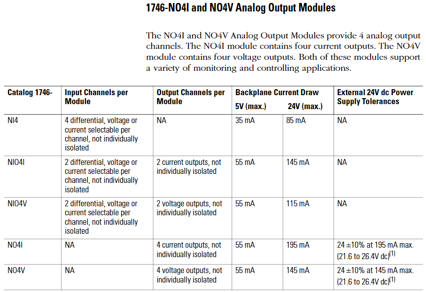
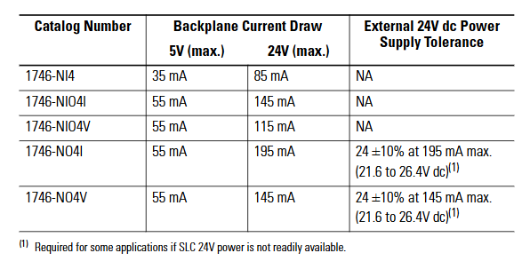
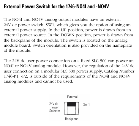
1746-NO4I 4-channel current (4-20mA) D/A conversion accuracy ± 0.1%, output short-circuit protection, inter group isolation valve positioner, frequency converter control
1746-NO4V 4-channel voltage (0-10V/± 10V) with the same structure as NO4I, output type is voltage, suitable for voltage control equipment, analog speed control motor, indicator light brightness adjustment
1746-NO8V 8-channel voltage (0-10V) 8-channel high-density, total output load current ≤ 100mA, supports synchronous control of multiple devices and multi-channel analog signal output (as displayed on the dashboard)
System installation and configuration
(1) Rack and power installation
Rack selection: Choose slot positions based on the number of modules. 1746-A7 (7 slots) is suitable for small and medium-sized systems, while 1746-A10 (10 slots) is suitable for large systems; If expansion is required, multiple rack connections can be achieved through the 1747-SN module.
Power calculation: It is necessary to calculate the 5V DC and 24V DC power consumption of all modules to ensure sufficient output capacity of the power module (e.g. 1746-P2 provides 24V DC 2.0A, 1746-P4 provides 4.0A). The calculation formula is: total power consumption=∑ (5V current of each module)+∑ (24V current of each module).
Installation specifications:
The rack should be installed vertically to avoid tilting (tilt angle ≤ 5 °) and ensure good heat dissipation;
The power module should be located near the input end of the rack to reduce wire voltage drop;
The grounding resistance is ≤ 4 Ω, and the rack shell needs to be separately grounded to avoid electromagnetic interference.
(2) Module installation steps
Static protection: Wear a grounding wristband before operation, store the module in an anti-static bag, and avoid touching the back panel pins.
Power off operation: Disconnect the power supply of the power rack before installation to prevent damage to the module or backplane caused by live plugging and unplugging.
Module insertion: Align the rack slot and slowly insert the module into the upper and lower self-locking tabs to secure it, without the need for additional screws; Idle slots require installation of 1746-N2 filling plates to prevent dust from entering.
Slot selection:
The processor module (such as 1747-L511) must be installed in slot 0;
Under high temperature conditions, install the heating module (such as a 32 point I/O module) in the rightmost slot (with a temperature tolerance of 60 ℃);
The analog module needs to be kept away from strong interference sources such as frequency converters and high-power motors to reduce signal fluctuations.
(3) Module address configuration
Address allocation principle:
Digital quantity module: Each 16 channel module occupies 1 input word/output word, and the 32 channel module occupies 2 input words/output words;
Analog module: Class 1 interface module (such as 1746-NI8) occupies 8 input words and 8 output words, while Class 3 interface module adds an additional status word address;
Address range: Input image area I: 0/0-I: 255/15, output image area O: 0/0-O: 255/15, avoid address overlap.
Configuration tool: Set the module ID code (such as 1746-NI8 Class 1 ID 3526) through RSLogix 500 programming software, and assign the corresponding input/output image area address. After configuration is complete, download it to the processor.
Wiring specifications and examples
(1) General Wiring Guidelines
Wire selection:
Digital module: Recommended 22-16 AWG shielded twisted pair (such as Belden 8761) to reduce electromagnetic interference;
Analog module: requires the use of twisted pair shielded wires (such as Belden 9239), with the shielding layer grounded at one end (near the signal source end) to avoid common mode interference;
Power cord: A 24V DC power supply requires the use of 18-14 AWG wires to ensure a voltage drop of ≤ 0.5V (the wire diameter needs to be increased for long-distance wiring).
Isolation and grounding:
The group isolation module needs to ensure that the common terminals (COM) of different groups are not connected together to avoid cross group short circuits;
The grounding of the analog module needs to be independent and separate from the power grounding, with a grounding resistance of ≤ 1 Ω;
The rack shell needs to be connected to the system grounding grid through grounding terminals to prevent static electricity accumulation.
Polarity and short circuit protection:
The DC module needs to strictly distinguish between positive and negative poles, and reverse connection may burn out the module (some modules have reverse connection protection);
The load end of the output module needs to be connected in series with a suitable fuse (such as 0.5A/250V) to prevent short circuit damage to the module caused by the load.
(2) Typical module wiring example
1746-IB32 (32 channel digital input):
4 sets of common terminals (COM1-COM4) correspond to channels 0-7, 8-15, 16-23, 24-31 respectively;
COM1-COM4 is connected to the negative pole of 24V DC, channels 0-31 are connected to the sensor output terminal, and+V1-V4 is connected to the positive pole of 24V DC;
When the current of a single group exceeds 2A, both common terminals of the group need to be connected simultaneously to avoid terminal overload.
1746-OB32E (32 channel digital output):
Two sets of common terminals (+V1,+V2) correspond to channels 0-15, 16-31;
+V1 and+V2 are connected to the positive pole of 24V DC, channels 0-31 are connected to the positive pole of the load, and the negative pole of the load is connected to the negative pole of 24V DC;
When a short circuit occurs, the E-Fuse LED lights up and automatically resets after the fault is removed, without the need to replace the fuse.
1746-NI8 (8-channel analog input):
Support single ended or differential wiring, single ended signals require the negative terminal of the signal to be short circuited to the common terminal (AGND);
Differential signals (such as 4-20mA) require the signal source to be positively connected to CHx (+) and negatively connected to CHx (-), with a common mode voltage of ≤± 10.5V;
The shielding layer is connected to the top shielding terminal of the module to avoid the introduction of interference signals.
Fault diagnosis and maintenance
(1) LED status diagnosis
Each module panel is equipped with status LEDs, which provide feedback on the operating status through light on/off/flashing. The core interpretation is as follows:
Module type LED identification status fault cause solution
The digital input channel light (CH0-CH31) is not on, the channel is not enabled/the wiring is disconnected/the sensor is faulty. 1. Check the configuration word to enable the channel; 2. Check the wiring and sensor power supply
Flashing open circuit/overvoltage/module internal fault 1. Measure input voltage (15-30V DC required); 2. Replace the module for testing
The digital output channel light (CH0-CH31) is not on, the channel is not enabled, the load is short circuited, and the electronic protection is triggered. 1. Check the configuration word and load; 2. Restart after removing the faulty load
OB32E E-Fuse is always on, corresponding to channel short circuit/overload. 1. Disconnect the load to check the short circuit point; 2. Wait for the module to cool down and reset automatically
Analog module status light (STATUS) flashing configuration error/over range/open circuit 1. Check the configuration word (input type/filter); 2. Measure signal range
Channel lights (CH0-CH7) flashing, channel open circuit/signal over range 1. Check wiring integrity; 2. Confirm that the signal source output is normal
(2) Common troubleshooting
Module unresponsive:
Reason: Backplane power supply failure, incorrect module insertion, incorrect address configuration;
Investigation: 1 Measure the 5V/24V voltage of the rack (in accordance with module requirements); 2. Re plug and unplug the module and check the locking of the buckle; 3. Confirm that the ID code and address allocation are correct.
Digital input signal loss:
Reason: Sensor malfunction, loose wiring, electromagnetic interference;
Investigation: 1 Measure the output voltage of the sensor (must be ≥ 15V DC conduction); 2. Re tighten the terminals; 3. Increase shielding or keep away from interference sources.
The analog signal fluctuates greatly:
Reason: Poor shielding grounding, long signal cables, and no filtering configuration;
Investigation: 1 Ensure that the shielding layer is grounded at one end; 2. Shorten cables or use signal amplifiers; 3. Reduce the filtering frequency in the configuration word (e.g. set to 1Hz).
(3) Daily maintenance suggestions
Regular inspection: Clean the module and rack dust every 3 months, check the tightness of the wiring terminals to avoid looseness and poor contact;
Environmental control: Ensure that the temperature inside the control cabinet is ≤ 60 ℃ and the humidity is ≤ 95% (without condensation). Install a cooling fan in high-temperature environments;
Spare parts management: Key modules (such as 1746-NI8, OB32E) require spare parts to be reserved for quick replacement in case of failure, reducing downtime;
Software backup: Regularly backup RSLogix 500 project files (including module configurations) to avoid recovery difficulties caused by configuration loss.
- OMRON
- ABB
- General Electric
- EMERSON
- Honeywell
- HIMA
- ALSTOM
- Rolls-Royce
- MOTOROLA
- Rockwell
- Siemens
- Woodward
- YOKOGAWA
- FOXBORO
- KOLLMORGEN
- MOOG
- KB
- YAMAHA
- BENDER
- TEKTRONIX
- Westinghouse
- AMAT
- AB
- XYCOM
- Yaskawa
- B&R
- Schneider
- KONGSBERG
- NI
- WATLOW
- ProSoft
- SEW
- ADVANCED
- Reliance
- TRICONEX
- METSO
- MAN
- Advantest
- STUDER
- DANAHER MOTION
- Bently
- Galil
- EATON
- MOLEX
- DEIF
- B&W
- ZYGO
- Aerotech
- DANFOSS
- Beijer
- Moxa
- Rexroth
- Johnson
- WAGO
- TOSHIBA
- BMCM
- SMC
- HITACHI
- HIRSCHMANN
- Application field
- XP POWER
- CTI
- TRICON
- STOBER
- Thinklogical
- Horner Automation
- Meggitt
- Fanuc
- Baldor
- SHINKAWA
- Other Brands
- UniOP
- KUKA
- Iba
- Beckhoff
-
 OMRON C60H C6DR DE V1 Sysmac PLC
 -
 MITSUBISHI ELECTRIC A2ACPU21 S1 CPU Module
 -
 ABB BAILEY INNPM12 Network Process Module
 -
 HONEYWELL 620 0073C IPC PLC Module
 -
 Mitsubishi 15050 PR02B PLC Circuit Board
 -
 SIEMENS 6SY7000 0AC37 Drive Control Module
 -
 OMRON TJ2 ECT16 Traxial EtherCAT Controller
 -
 GE Fanuc IC698PSD300D Power Supply Module
 -
 Texas Instruments Series 505 16 Position Base
 -
 OMRON YASKAWA SGDH 10DE OY Servo Drive
 -
 Allen‑Bradley 440G-MT Safety Interlock Switch Specs
 -
 Rubycon PD27A 24V 8A Power Supply Module
 -
 SK-H1-GDB1-F11D PLC Gate Driver Board Kit
 -
 VIPA 441-4UA14 451-4UA14 PLC Module Rack
 -
 Mitsubishi FX5U-80MT ESS PLC Controller Specs
 -
 Mitsubishi Q64TCRTN Temperature PLC Module
 -
 GE 1C31170G Rev10 PLC Circuit Board Module
 -
 Schneider TWDLMDA40DTK PLC Controller Module
 -
 Omron FQM1-MMA22 Motion Control Module Specs
 -
 OMRON CJ1W-NCF71 Position Control Unit Specs
 -
 Schneider TSXETY4103 Ethernet Module
 -
 Mitsubishi Q12PHCPU Process CPU
 -
 Yaskawa 3G3HV-A4022-CE AC Drive
 -
 Cincinnati Milacron 3-533-0669G Temperature Control Board
 -
 Allen Bradley 20AC030A3AYNANC0 PowerFlex 70 Drive
 -
 Siemens 6ES7314-6BG03-0AB0 CPU 314C-2 DP
 -
 Carrier 17EX54007903 PLC Module
 -
 OMRON CS1W-V600C12 ID Controller Module
 -
 Honeywell 51402755-100 PCB Card
 -
 Heidenhain ECN 113 Rotary Encoder
 -
 OMRON B7AM-8B16 I/O Terminal Block
 -
 Fanuc A06B-6110-H026 Power Supply Module
 -
 Schneider TSXETG3021 Ethernet Gateway
 -
 OMRON CS1W-CLK21-V1 Controller Link Unit
 -
 NP1W6406T-Z704 PLC I/O Module
 -
 OMRON CJ1W-DA08C Analog Output Module
 -
 Yaskawa 3G3HV-A4022-CE AC Drive
 -
 OMRON NB7W-TW01B CP1L-EL20DR-D Power Panel
 -
 OMRON C500-NC103-E Position Control Unit
 -
 Steag Hamatech PLC DCS Servo Control System
 -
 Siemens 6SN1123-1AA00-0DA1 Power Supply Module
 -
 GE IC693CHS391H CPU & AD693CMM301A PLC Module
 -
 Siemens 6FC5303-0AF23-1AA1 PLC Control Panel
 -
 Square D CM4000T PowerLogic Circuit Monitor J1 F16
 -
 Siemens 6FX5002-5DG10-1BA0 MOTION-CONNECT 500 Cable
 -
 Schmersal SRB324ST 101195504 Safety Relay 24V
 -
 Mitsubishi 15050-PR02A PLC Circuit Board Module
 -
 OMRON CQM1-AD041 Analog Input PLC Module
 -
 Beckhoff EL5042 EtherCAT PLC Terminal Module
 -
 OMRON C200HW-MC402-E Motion Control Unit
 -
 C36TC0UA1100 Industrial Temperature Controller
 -
 NL8048BC24 12 Industrial Control LCD Module
 -
 OMRON R88D Servo Drive and Motor System
 -
 OMRON CS1W CLK21 V1 Controller Link Module
 -
 OMRON YASKAWA R7M A20030 S1 D Servo Motor
 -
 SIEMENS 6AV2128 3KB06 0AX1 Unified Comfort Panel
 -
 Schneider Electric METSEPM8240 PowerLogic Meter
 -
 Advanced AMCI 1PLC 1 31F Programmable Limit Switch
 -
 ABB PM582 ETH Programmable Logic Processor
 -
 SIEMENS 6FC5110 0CB01 0AA0 CPU Control Board
 -
 Schleicher P03GS13A CPU Module
 -
 Siemens 6SN1123-1AA00-0BA1 Power Module
 -
 Mitsubishi A1S61PN Power Supply Module
 -
 Yaskawa CPS-IONB DC Power Supply Module
 -
 Siemens 6ES7215-2BD00 CPU 215-2
 -
 Mitsubishi A2ACPU MELSEC PLC System Kit
 -
 ProSoft 3150-MCM Communication Module
 -
 Mitsubishi OSE104ET Incremental Encoder
 -
 OMRON CJ1W-AD081-V1 Analog Input Module
 -
 Broadcom BCM5464A1KRB Quad Port Ethernet IC
 -
 Modicon M221-24IO TM221C24 PLC 24 PNP Transistor
 -
 Allen-Bradley 1321-3R160-B Line Reactor 3R160B
 -
 Beckhoff CX1020-0012 Embedded PLC Module Specs
 -
 Turck BL20-PF-24VDC-D Power Feed Module Specs
 -
 Siemens 6SY7000-0AC37 Power Supply Module
 -
 Yaskawa SGDH-10DE-OY 1kW 400V Servo Drive Specs
 -
 Omron 3G3SV-BB015-E 1.5kW 220V VFD Specs
 -
 Uni-Pro CPU91-PLC J 23.020167X Processor Module
 -
 PASABAN MTC-3044 PLC Rack Power Supply 4835-A
 -
 XYCOM 3015T Operator Interface Panel BIN4.4.4
 -
 OMRON CJ1W-MD261 Mixed I/O Module
 -
 Omron NJ301-1100 PLC CPU eCat EIP Specs
 -
 Omron F500-C15-ETN Vision System PLC Module
 -
 Modicon M241-24IO TM/T2UK PLC with Ethernet
 -
 SIXNET YS-800-001 RTU PLC Module
 -
 BEMAC UST-202-D Interface Board 1307D V08B2
 -
 Yaskawa JANCD-MMOIC-02 Drive Circuit Board
 -
 ABB 3BSE005028R1 SDCS-COM-1 Comm Board
 -
 Omron 3G3MX2-A4110 A4150 Inverter Drives Specs
 -
 KEYENCE CA-E100 PLC Module
 -
 GE IC693ALG223-GB Analog Input Module Specs
 -
 ABB BAILEY IMMFP01 Multi Function Processor System
 -
 SIEMENS 6FC5372 0AA00 0AA1 NCU 7202 Controller
 -
Modicon TM241CE4 40I O Transistor Programmable Controller
-
 SIEMENS 6ES7 315 2EH13 0AB0 CPU 3152 PN DP
 -
 NORIS A1 91 PCB Card Rack Module System
 -
 SIEMENS 6ES7 313 5BE01 0AB0 Compact CPU
 -
 SCHNEIDER ELECTRIC S144B MICROLOGIC 60A Trip Unit
 -
 CNI PLC269 v3 Control Module Board Rev H
 -
ABB BAILEY IIMCP02 Processor Module
-
 OMRON NT20S ST121 EV3 Operator Interface Terminal
 -
 OMRON NS-CA001 Video Input Unit
 -
 GE Fanuc IC695CHS012 RX3i Backplane
 -
 Allen Bradley 2711E-K14C6 PanelView 1400e Terminal
 -
 Siemens Sinamics CCB 10000432.71 Power Cell
 -
 Siemens 6SL3210-1SE21-8UA0 Power Module PM340
 -
 Yaskawa CIMR-F7A20P4 AC Drive
 -
 Beckhoff EP1918-0002 EtherCAT Box I/O Module
 -
 OMRON CQM1-TC001 Temperature Control Module
 -
 GE Fanuc SGHA36AT0400 Industrial Contactor
 -
 OMRON NJ501-1500 PLC Machine Automation Controller
 -
 Mitsubishi MAZAK QX084 Power Supply MELDAS 500 CNC
 -
 B&R 0AC808.9 PLC Automation Module
 -
 OMRON CP1H-XA40DT1-D PLC Module
 -
 G&W Electric PLC15 5111 011 15kV Capnut Assembly
 -
 GE DS200SLCCG3AGH PCB Circuit Board
 -
 Siemens SINUMERIK 6FC3981-4FD PLC Extension
 -
 OMRON F300-DC I/O Image Processing Unit
 -
 FANUC A06B-0314-B002 AC Servo Motor
 -
 GC-S84 Programmable Controller Logic Module
 -
 PASABAN MONTELEC MTC3001-DC Drive Control PLC
 -
 Allen Bradley 100E460EJ11 Auxiliary Contactor
 -
 Bosch Rexroth 1070075337-101 Card Parameters
 -
 HMS Anybus AB7646-F Gateway Specifications
 -
 Bosch 062633-303401 CNC Servo PLC Card
 -
 TI 500-5023 Series PLC Power Supply
 -
 Siemens C98043-A7002-L1-12 Circuit Board
 -
 Omron E5CC-RX3A5M-000 Controller


