
Allen-Bradley SLC 500 ™ Installation Guide for 32 Channel Digital I/O Module
Core restriction: Live replacement of components or wiring is prohibited in hazardous environments. Component replacement must use original factory accessories, otherwise it may damage the explosion-proof characteristics.
Allen-Bradley SLC 500 ™ Installation Guide for 32 Channel Digital I/O Module
Product scope of application and requirements for hazardous environments
(1) Applicable scenarios
Environmental classification: Only applicable to Class I, Division 2 hazardous environments (Groups A, B, C, D) or non hazardous environments, prohibited for use in higher-level hazardous areas (such as Class I, Division 1).
Core restriction: Live replacement of components or wiring is prohibited in hazardous environments. Component replacement must use original factory accessories, otherwise it may damage the explosion-proof characteristics.
(2) Multi language support
The document contains bilingual hazardous environment warnings in English and French, with the French version emphasizing component replacement risks and power outage operation requirements, adapting to the compliance needs of the European market.
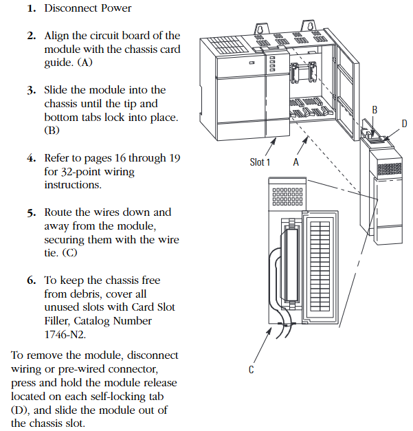
Module overview and installation process
(1) Module positioning
The 1746 series 32 channel digital I/O module is a dedicated module for SLC 500 chassis, which is divided into input modules (IB32, IV32) and output modules (OB32, OB32E, OV32). Its core function is to achieve bidirectional interaction between industrial field digital signals (such as sensors and actuators) and PLC, supporting 24V DC mainstream industrial voltage. It is designed according to "group isolation" (input 4 groups/8 points, output 2 groups/16 points) to reduce signal interference.
(2) Standard installation steps (power-off operation)
Power off preparation: Disconnect the chassis power supply to ensure no voltage input.
Module alignment: Align the module circuit board with the chassis card slot to avoid touching the backplane pins (to prevent static damage).
Insertion fixation: Slowly push the module into the upper and lower self-locking tabs to tighten, without the need for additional screws.
Wiring arrangement: After wiring, comb down the wires and fix them in the module slot with cable ties to avoid blocking heat dissipation or loosening.
Idle slot handling: Cover the idle slots with 1746-N2 slot filling plates to prevent dust from entering the chassis.
(3) Module disassembly
First, disconnect the external wiring or pre wired connector, press the release tabs up and down on the module, and pull out the module horizontally. Do not forcefully pull or pull it.
Core technical specifications
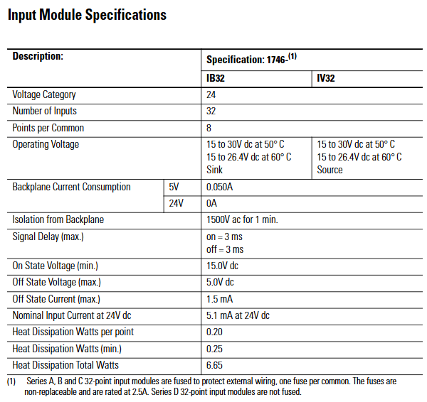
(1) Input module specifications (IB32, IV32)
Specification category 1746-IB32 (24V DC sinking input) 1746-IV32 (24V DC sourcing input)
Number of channels: 32 channels, 32 channels
8 points per group/public end (4 groups in total, isolated between groups) 8 points per public end (4 groups in total, isolated between groups)
Working voltage 15-30V DC (50 ℃), 15-26.4V DC (60 ℃) 15-30V DC (50 ℃), 15-26.4V DC (60 ℃)
Backplane current consumption 5V DC 0.050A, 24V DC 0A, 5V DC 0.050A, 24V DC 0A
Backboard isolation voltage 1500V AC (1 minute) 1500V AC (1 minute)
Signal delay (maximum) 3ms for both on/off and 3ms for both on/off
Conducting voltage (minimum) 15.0V DC 15.0V DC
Turn off voltage (maximum) 5.0V DC 5.0V DC
Turn off current (maximum) 1.5mA 1.5mA
24V DC nominal input current 5.1mA 5.1mA
Total heat dissipation power 6.65W (0.20W per point, minimum 0.25W) Total 6.65W (0.20W per point, minimum 0.25W)
Fuse protection (Series A/B/C) with 1 non replaceable 2.5A fuse per group, Series D without 1 non replaceable 2.5A fuse per group, Series D without
(2) Output module specifications (OB32, OB32E, OV32)
Specification category 1746-OB32 (Series D, 24V DC sourcing output) 1746-OB32E (24V DC sourcing with electronic protection) 1746-OV32 (Series D, 24V DC sinking output)
Number of channels: 32 channels, 32 channels, 32 channels
16 points per group/common end (2 groups in total, isolated between groups) 16 points per common end (2 groups in total, isolated between groups) 16 points per common end (2 groups in total, isolated between groups)
Working voltage 5-50V DC 10-30V DC 5-50V DC
Backplane current consumption 5V DC 0.190A, 24V DC 0A 5V DC 0.190A, 24V DC 0A 5V DC 0.190A, 24V DC 0A
Backboard isolation voltage 1500V AC (1 minute) 1500V AC (1 minute) 1500V AC (1 minute)
Signal delay (maximum) conducts 0.1ms, turns off 1.0ms conducts 0.1ms, turns off 1.0ms conducts 1.0ms, turns off 2.0ms
Turn off leakage current (maximum) 1mA 1mA 1mA 1mA
Minimum load current 1mA 1mA 1mA
Module total continuous current (maximum) 8.0A (0-60 ℃) 8.0A (0-60 ℃) 8.0A (0-60 ℃)
Single channel continuous current (maximum) 0.50A at 30 ℃, 0.25A at 60 ℃, 0.50A at 30 ℃, 0.25A at 60 ℃, 0.50A at 30 ℃, and 0.25A at 60 ℃
Continuous current per group (maximum) 4.0A (0-60 ℃) 4.0A (0-60 ℃) 4.0A (0-60 ℃)
Continuous current per pin (maximum) 2.0A (0-60 ℃) 2.0A (0-60 ℃) 2.0A (0-60 ℃) 2.0A (0-60 ℃)
Voltage drop during conduction (maximum) 1.2V (at 0.5A) 1.2V (at 0.5A) 1.2V (at 0.5A)
Surge current (per point) 1.0A/10ms at 30 ℃ (once per second), 1.0A/10ms at 60 ℃ (once every 2 seconds), 1.0A/10ms at 30 ℃ (once per second), 1.0A/10ms at 60 ℃ (once every 2 seconds), 1.0A/10ms at 30 ℃ (once per second), 1.0A/10ms at 60 ℃ (once every 2 seconds)
Electronic protection None (short circuit, overload thermal cut-off protection) None
- OMRON
- ABB
- General Electric
- EMERSON
- Honeywell
- HIMA
- ALSTOM
- Rolls-Royce
- MOTOROLA
- Rockwell
- Siemens
- Woodward
- YOKOGAWA
- FOXBORO
- KOLLMORGEN
- MOOG
- KB
- YAMAHA
- BENDER
- TEKTRONIX
- Westinghouse
- AMAT
- AB
- XYCOM
- Yaskawa
- B&R
- Schneider
- KONGSBERG
- NI
- WATLOW
- ProSoft
- SEW
- ADVANCED
- Reliance
- TRICONEX
- METSO
- MAN
- Advantest
- STUDER
- DANAHER MOTION
- Bently
- Galil
- EATON
- MOLEX
- DEIF
- B&W
- ZYGO
- Aerotech
- DANFOSS
- Beijer
- Moxa
- Rexroth
- Johnson
- WAGO
- TOSHIBA
- BMCM
- SMC
- HITACHI
- HIRSCHMANN
- Application field
- XP POWER
- CTI
- TRICON
- STOBER
- Thinklogical
- Horner Automation
- Meggitt
- Fanuc
- Baldor
- SHINKAWA
- Other Brands
- UniOP
- KUKA
- Iba
- Beckhoff
-
 OMRON B7AM-8B16 I/O Terminal Block
 -
 Fanuc A06B-6110-H026 Power Supply Module
 -
 Schneider TSXETG3021 Ethernet Gateway
 -
 OMRON CS1W-CLK21-V1 Controller Link Unit
 -
 NP1W6406T-Z704 PLC I/O Module
 -
 OMRON CJ1W-DA08C Analog Output Module
 -
 Yaskawa 3G3HV-A4022-CE AC Drive
 -
 OMRON NB7W-TW01B CP1L-EL20DR-D Power Panel
 -
 OMRON C500-NC103-E Position Control Unit
 -
 Steag Hamatech PLC DCS Servo Control System
 -
 Siemens 6SN1123-1AA00-0DA1 Power Supply Module
 -
 GE IC693CHS391H CPU & AD693CMM301A PLC Module
 -
 Siemens 6FC5303-0AF23-1AA1 PLC Control Panel
 -
 Square D CM4000T PowerLogic Circuit Monitor J1 F16
 -
 Siemens 6FX5002-5DG10-1BA0 MOTION-CONNECT 500 Cable
 -
 Schmersal SRB324ST 101195504 Safety Relay 24V
 -
 Mitsubishi 15050-PR02A PLC Circuit Board Module
 -
 OMRON CQM1-AD041 Analog Input PLC Module
 -
 Beckhoff EL5042 EtherCAT PLC Terminal Module
 -
 OMRON C200HW-MC402-E Motion Control Unit
 -
 C36TC0UA1100 Industrial Temperature Controller
 -
 NL8048BC24 12 Industrial Control LCD Module
 -
 OMRON R88D Servo Drive and Motor System
 -
 OMRON CS1W CLK21 V1 Controller Link Module
 -
 OMRON YASKAWA R7M A20030 S1 D Servo Motor
 -
 SIEMENS 6AV2128 3KB06 0AX1 Unified Comfort Panel
 -
 Schneider Electric METSEPM8240 PowerLogic Meter
 -
 Advanced AMCI 1PLC 1 31F Programmable Limit Switch
 -
 ABB PM582 ETH Programmable Logic Processor
 -
 SIEMENS 6FC5110 0CB01 0AA0 CPU Control Board
 -
 Schleicher P03GS13A CPU Module
 -
 Siemens 6SN1123-1AA00-0BA1 Power Module
 -
 Mitsubishi A1S61PN Power Supply Module
 -
 Yaskawa CPS-IONB DC Power Supply Module
 -
 Siemens 6ES7215-2BD00 CPU 215-2
 -
 Mitsubishi A2ACPU MELSEC PLC System Kit
 -
 ProSoft 3150-MCM Communication Module
 -
 Mitsubishi OSE104ET Incremental Encoder
 -
 OMRON CJ1W-AD081-V1 Analog Input Module
 -
 Broadcom BCM5464A1KRB Quad Port Ethernet IC
 -
 Modicon M221-24IO TM221C24 PLC 24 PNP Transistor
 -
 Allen-Bradley 1321-3R160-B Line Reactor 3R160B
 -
 Beckhoff CX1020-0012 Embedded PLC Module Specs
 -
 Turck BL20-PF-24VDC-D Power Feed Module Specs
 -
 Siemens 6SY7000-0AC37 Power Supply Module
 -
 Yaskawa SGDH-10DE-OY 1kW 400V Servo Drive Specs
 -
 Omron 3G3SV-BB015-E 1.5kW 220V VFD Specs
 -
 Uni-Pro CPU91-PLC J 23.020167X Processor Module
 -
 PASABAN MTC-3044 PLC Rack Power Supply 4835-A
 -
 XYCOM 3015T Operator Interface Panel BIN4.4.4
 -
 OMRON CJ1W-MD261 Mixed I/O Module
 -
 Omron NJ301-1100 PLC CPU eCat EIP Specs
 -
 Omron F500-C15-ETN Vision System PLC Module
 -
 Modicon M241-24IO TM/T2UK PLC with Ethernet
 -
 SIXNET YS-800-001 RTU PLC Module
 -
 BEMAC UST-202-D Interface Board 1307D V08B2
 -
 Yaskawa JANCD-MMOIC-02 Drive Circuit Board
 -
 ABB 3BSE005028R1 SDCS-COM-1 Comm Board
 -
 Omron 3G3MX2-A4110 A4150 Inverter Drives Specs
 -
 KEYENCE CA-E100 PLC Module
 -
 GE IC693ALG223-GB Analog Input Module Specs
 -
 ABB BAILEY IMMFP01 Multi Function Processor System
 -
 SIEMENS 6FC5372 0AA00 0AA1 NCU 7202 Controller
 -
Modicon TM241CE4 40I O Transistor Programmable Controller
-
 SIEMENS 6ES7 315 2EH13 0AB0 CPU 3152 PN DP
 -
 NORIS A1 91 PCB Card Rack Module System
 -
 SIEMENS 6ES7 313 5BE01 0AB0 Compact CPU
 -
 SCHNEIDER ELECTRIC S144B MICROLOGIC 60A Trip Unit
 -
 CNI PLC269 v3 Control Module Board Rev H
 -
ABB BAILEY IIMCP02 Processor Module
-
 OMRON NT20S ST121 EV3 Operator Interface Terminal
 -
 OMRON NS-CA001 Video Input Unit
 -
 GE Fanuc IC695CHS012 RX3i Backplane
 -
 Allen Bradley 2711E-K14C6 PanelView 1400e Terminal
 -
 Siemens Sinamics CCB 10000432.71 Power Cell
 -
 Siemens 6SL3210-1SE21-8UA0 Power Module PM340
 -
 Yaskawa CIMR-F7A20P4 AC Drive
 -
 Beckhoff EP1918-0002 EtherCAT Box I/O Module
 -
 OMRON CQM1-TC001 Temperature Control Module
 -
 GE Fanuc SGHA36AT0400 Industrial Contactor
 -
 OMRON NJ501-1500 PLC Machine Automation Controller
 -
 Mitsubishi MAZAK QX084 Power Supply MELDAS 500 CNC
 -
 B&R 0AC808.9 PLC Automation Module
 -
 OMRON CP1H-XA40DT1-D PLC Module
 -
 G&W Electric PLC15 5111 011 15kV Capnut Assembly
 -
 GE DS200SLCCG3AGH PCB Circuit Board
 -
 Siemens SINUMERIK 6FC3981-4FD PLC Extension
 -
 OMRON F300-DC I/O Image Processing Unit
 -
 FANUC A06B-0314-B002 AC Servo Motor
 -
 GC-S84 Programmable Controller Logic Module
 -
 PASABAN MONTELEC MTC3001-DC Drive Control PLC
 -
 Allen Bradley 100E460EJ11 Auxiliary Contactor
 -
 Bosch Rexroth 1070075337-101 Card Parameters
 -
 HMS Anybus AB7646-F Gateway Specifications
 -
 Bosch 062633-303401 CNC Servo PLC Card
 -
 TI 500-5023 Series PLC Power Supply
 -
 Siemens C98043-A7002-L1-12 Circuit Board
 -
 Omron E5CC-RX3A5M-000 Controller
 -
 CN-8032-L Profinet Network Adapter Module
 -
 Siemens 3TK2804-0BB4 Safety Relay Details
 -
 Toledo TTLM-2-1M I/O Load Module
 -
 NORIS A1-91 PLC Rack Board Specifications
 -
 Mitsubishi A3ACPUR21 MELSEC PLC CPU Module
 -
 Beckhoff EP7041‑3002 EtherCAT Box Digital Input Module
 -
 REER EOS2E 1053 EOS2R 1053 Safety Light Curtain
 -
 Mitsubishi Q80BD-J71BR11 MELSECNET/H Interface Board
 -
 Omron 3G3IV-B4220-EV2 VFD 400V 22kW
 -
 Allen-Bradley 96844671 1785-LT3 PLC-5/12 Processor Module
 -
 Pasaban MTC3001-DC Drive Control PLC Module
 -
 Omron CJ1M-CPU11 V4.0 PLC CPU Module
 -
 ABB CM579-PNIO B3 Communication Module
 -
 B&R X20 AI 4221 Analog Module
 -
 Siemens 6SY7000-0AC80 PLC Module
 -
 GE 531X300CCHAFM5 Control Card
 -
 AB 810-A15C Inverse Time Relay
 -
 WITTENSTEIN LP120X-MF2-20 Planetary Gear
 -
 Mitsubishi Kakoki E-01B-4130 PLC I/O Modules
 -
 ABB DSQC643 Safety Control Board
 -
 Siemens G26004-A2105-P100-2 PCB
 -
 OMRON F350-C10E Image Processing Unit
 -
 FUJI UG430H-TS1 HMI Touch Panel
 -
 Westronics CB100188-01 Rev F Board
 -
 Siemens 7MH4900-3AA01 Weighing Module
 -
 Gilbert & Nash Tracker 2000 Control Cabinet
 -
 OMRON CJ1M-CPU22 CPU Unit
 -
 OMRON F3SJ-E0625P25 Light Curtain
 -
 Siemens 3VA2340-5HL32-0AA0 Breaker
 -
 Mitsubishi Melsec A61P A2NCPU PLC System


