
Molex SST-ESR2-CLX-RLL and SST-SR4-CLX-RLL communication modules
PC hardware should have at least an Intel Pentium 4 processor, 512MB of memory, and 100MB of available hard disk space; Suggest a 17 inch/19 inch (1280 × 1024 and above resolution) monitor; CD/DVD drive, power cable, Ethernet cable, keyboard and mouse required
The PAC/PLC power ESR2 module consumes 5VDC 850mA and 24VDC 1.75mA; The SR4 module consumes 5VDC 1004mA and 24VDC 1.75mA. Please refer to the CLX 5000 modular installation and operation manual to calculate the total power load
The PC operating system supports Windows XP, Vista, 7, and 8
Other requirements: 1. Support for Rockwell Automation RSLogix 5000 Additional Instructions (AOI) requires RSLogix 5000 V16 or above, module firmware must be 2.10.2 or above (general configuration file) or 2.12.1 or above (additional configuration file/AOP), BCMS software must be 1.9 or above
Molex SST-ESR2-CLX-RLL and SST-SR4-CLX-RLL communication modules
System and hardware requirements
(1) System requirements
Category specific requirements
PC hardware should have at least an Intel Pentium 4 processor, 512MB of memory, and 100MB of available hard disk space; Suggest a 17 inch/19 inch (1280 × 1024 and above resolution) monitor; CD/DVD drive, power cable, Ethernet cable, keyboard and mouse required
The PAC/PLC power ESR2 module consumes 5VDC 850mA and 24VDC 1.75mA; The SR4 module consumes 5VDC 1004mA and 24VDC 1.75mA. Please refer to the CLX 5000 modular installation and operation manual to calculate the total power load
The PC operating system supports Windows XP, Vista, 7, and 8
Other requirements: 1. Support for Rockwell Automation RSLogix 5000 Additional Instructions (AOI) requires RSLogix 5000 V16 or above, module firmware must be 2.10.2 or above (general configuration file) or 2.12.1 or above (additional configuration file/AOP), BCMS software must be 1.9 or above
2. Support for RSLogix 5000 additional configuration files (AOP) requires RSLogix 5000 V15 or above version, module firmware 2.3.0 or above, BCMS software 1.7.0 or above, and AOP only supports maximum input/output/status INT size (250, 248, 250), small size requires 1756 universal configuration file
(2) Hardware and Packaging
package contents
The module model includes items and quantities
SST-ESR2-CLX-RLL 1 communication module, 2 RJ45 to DB9 serial cable adapters, 1 Windows system installation CD (including BCMS software), PDF versions of the CD including user guide, Siemens Industrial Ethernet protocol guide, Modbus TCP/serial protocol guide
SST-SR4-CLX-RLL 1 communication module, 4 RJ45 to DB9 serial cable adapters, 1 Windows system installation CD (including BCMS software), CD containing user guide, Modbus serial protocol guide PDF version (Siemens Industrial Ethernet, Modbus TCP protocol guide PDF included but not applicable)
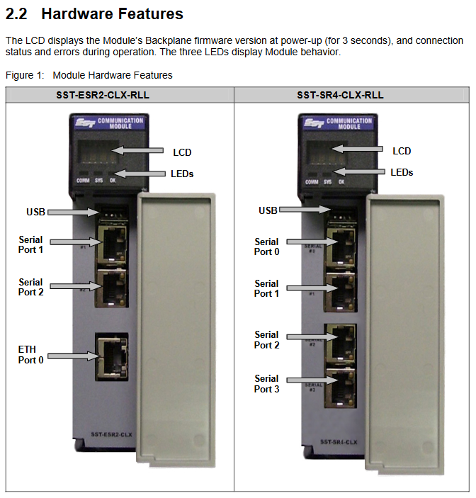
Hardware features: All include status LEDs (COMM, SYS, OK, indicating communication/connection/initialization status respectively), RJ45 serial interface (connecting RS232/422/485 devices with transmit/receive indicator lights), USB configuration port (downloading configuration/upgrading firmware); ESR2 additionally includes an RJ45 Ethernet interface (connected to industrial networks with activity/link indicator lights), while SR4 does not have an Ethernet interface; All have self-locking tongue fixing modules, and LCD displays firmware version, connection status, IP address, and other information.
Core functions and software
(1) Core functions of the product
Differences and Commonalities of Modules
Function SST-ESR2-CLX-RLL SST-SR4-CLX-RLL
Number of interfaces: 1 Ethernet port+2 serial ports+4 serial ports
Supports protocol Modbus TCP/serial, Siemens S5/S7 communication only Modbus serial communication
Common feature 1. Supports two database addressing modes: default and extended. In default mode, 0-699 address mapping is used for CLX input/output/status tables. In extended mode, 30K address mapping can be customized
2. Support cyclic function (read and write data periodically, up to 255 per channel), which can be dynamically triggered
3. Supports AOI/AOP and CIP messaging (reading and writing databases, triggering cyclic functions)
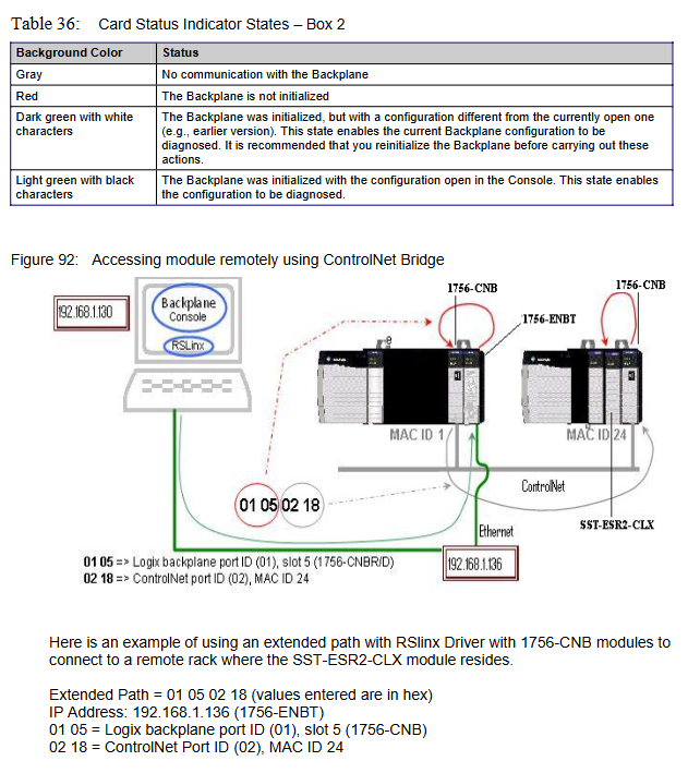
4. Supports remote rack configuration, Listen Only mode, and can be configured as client/server (master-slave) mode
Protocol support details: Modbus supports function codes such as FC3 (read multiple registers), FC6 (write single registers), FC16 (write multiple registers), etc; Siemens S5/S7 supports reading and writing of variable types such as ABx/AWx, EBx/EWx, MBx/MWx, DBx.DBx, etc.
(2) Software and Tools
BCMS software: Brad Communication ™ The SST backplane communication module software includes Configuration Manager (managing configuration files, such as creating/uploading/downloading configurations, modifying IP addresses), Console (configuring ports/protocols/devices, creating cyclic functions, including tools such as PCInit/ReadWait/WriteWait). After installation, the configuration files, AOI files, and firmware are stored in the corresponding system paths (Windows XP/7 paths differ).
Diagnostic and management tools: including Visucyc (monitoring cyclic function status), Network Diagnostic (diagnosing ESR2 Ethernet activity), Firmware Installer (upgrading firmware), etc., supporting module connection through USB, RSLinx, TCP/IP, and other methods.
Configuration and Operation Guide
(1) Quick configuration process
Backplane communication verification: The module supports live plugging and unplugging (RIPP). During installation, align the guide rail and insert it into the rack. Configure the EtherNet/IP driver through RSLinx and browse the rack to confirm that the module is recognized (ESR2 product code 53, SR4 product code 54).
Module configuration (RSLogix 5000)
AOP configuration (recommended): You need to install the AOP installation package first, add the SST-ESR2/SR4-CLX-RLL module to RSLogix 5000, configure the slot, connection type (Output w/Status/Sten Only), RPI (5-750ms), program mode output status (such as Zero CyclicRuns), and ensure that the configuration name is consistent with the module.
General configuration file: Add 1756-MODULE, set communication format (such as Data INT with Status), assembly instance and size for input/output/configuration/status (such as input instance 1, size 250).
Initialization and Address Mode Switching: Initialize the module through Console's PCInit; The database address mode can be switched in Configuration Manager. The default mode maps the CLX table from 0-699, and the extended mode allows customization of input/output/status addresses and lengths (firmware 2.10.2 or above is required).
(2) Typical Configuration Example
Modbus TCP configuration: ESR2 can be configured as a server (select Modbus TCP protocol), client (add Modbus device, set IP address), or both client and server, creating cyclic functions (set cycle, data volume, device address, database offset).
Modbus serial configuration: Both modules can be configured as slaves (select Modbus RTU/ASCII Slave) or hosts (add Modbus slave devices, set slave numbers), supporting multi-channel master-slave hybrid configuration.
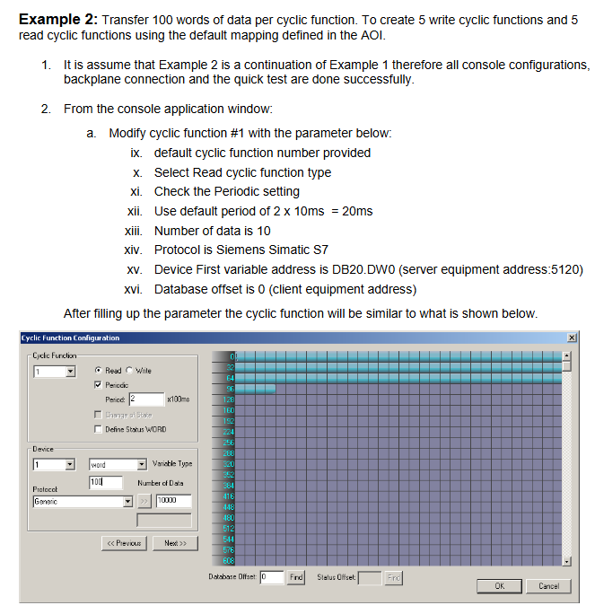
Siemens S7/S5 configuration: Only supported by ESR2, can be configured as a server/client, adding devices such as S7 300/400/1200, creating cyclic functions to read and write variables such as DBx.DWx.
Compliance and Support
(1) Compliance certification
Compliant with CE/EU, RoHS, FM (Class 1 Div 2 Groups A-D), FCC, Korean certification, RINA certification, electrical safety complies with EN 61010-1, EMC complies with EN 61000-6-2/4.
(2) Warranty and Support
Warranty: According to Molex standard warranty terms, please refer to Appendix F of the document for details.
Technical Support: You can contact Molex Canada at 216 Bathurst Drive, Waterloo, Ontario, Canada N2V 2L7; Phone: 1.775.782.3611 or 1.800.227.5514 (US only), or visit the official website Bently.com for patent information and the latest documents.
- OMRON
- ABB
- General Electric
- EMERSON
- Honeywell
- HIMA
- ALSTOM
- Rolls-Royce
- MOTOROLA
- Rockwell
- Siemens
- Woodward
- YOKOGAWA
- FOXBORO
- KOLLMORGEN
- MOOG
- KB
- YAMAHA
- BENDER
- TEKTRONIX
- Westinghouse
- AMAT
- AB
- XYCOM
- Yaskawa
- B&R
- Schneider
- KONGSBERG
- NI
- WATLOW
- ProSoft
- SEW
- ADVANCED
- Reliance
- TRICONEX
- METSO
- MAN
- Advantest
- STUDER
- DANAHER MOTION
- Bently
- Galil
- EATON
- MOLEX
- DEIF
- B&W
- ZYGO
- Aerotech
- DANFOSS
- Beijer
- Moxa
- Rexroth
- Johnson
- WAGO
- TOSHIBA
- BMCM
- SMC
- HITACHI
- HIRSCHMANN
- Application field
- XP POWER
- CTI
- TRICON
- STOBER
- Thinklogical
- Horner Automation
- Meggitt
- Fanuc
- Baldor
- SHINKAWA
- Other Brands
- UniOP
- KUKA
- Iba
- Beckhoff
-
 Siemens SINUMERIK 840D SL NCU 720.3B with PLC 317-3 PN/DP
 -
 Siemens 6AV6618-7GD01-3AB0 HMI Panel
 -
 OMRON F150-C15E-3 Vision Mate Controller PLC Overview
 -
 Mitsubishi MELSEC A Series PLC System A63P A3ACPU A616AD A68RD3
 -
 M68-2000 2 Axis Motion Controller SCE SERVO CNC
 -
 OMRON FZ-S2M PLC Camera Vision System
 -
 VISOLUX SLVA-4K PLC Module from Elektronik GmbH
 -
 OMRON CJ1M-CPU23 V2.0 PLC CPU Unit
 -
 ABB AI86-16CHF PCB Card 5761751-9 B Specifications
 -
 Allen-Bradley 100-D140ZJ22L Contactor Overview
 -
 Merlin Gerin PB80 PLC Rack
 -
 WEIR WE203 Power Supply PLC
 -
 OMRON NX-TS3102 Temperature Input Unit
 -
 Siemens 6ES7146-6FF00-0AB0 I/O Module
 -
 Fanuc A16B-3300-0057 Circuit Board
 -
 OMRON CJ1W-IDP01 Input Module
 -
 Siemens 6FX2007-1AD13 Handheld Unit
 -
 Gems EM54 PLC Module PCB
 -
 Beckhoff CX2030-0121 Embedded PC CPU
 -
 OMRON NJ301-1100 Machine Automation Controller
 -
 Biesse Rover CNI PLC 2153 030 7146.30 Numerical Control Module
 -
 OMRON CJ1W DA08V Analog Output Module
 -
 OMRON CS1D ETN21D Ethernet Module
 -
 Allen Bradley 1768 L43 CompactLogix Controller
 -
 Schneider TWDLMDA40DTK Twido PLC Module
 -
 Mitsubishi NZ2EX2B 60AD4 Analog Input Module
 -
 OMRON NS8 TV00B V2 Touch Display Panel
 -
 Mitsubishi AY71 CMOS TTL Output Module
 -
 OMRON C500 CPU11 E Processor Module
 -
 OMRON CJ1W PTS51 Temperature Input Module
 -
 Siemens 6SL3100-1DE22-0AA1 600V DC Supply
 -
 OMRON CJ1M-CPU23 PLC CPU 9‑Pin Serial
 -
 Schlumberger IMT4N 24‑250VAC 48‑230VAC PLC Timer
 -
 OMRON CJ1M-CPU22 PLC CPU Unit V2.0
 -
 Allen‑Bradley 2711P-B7C6D2 Touch Screen PanelView
 -
 ADSP-2181KST-160 Analog Devices DSP IC Specs
 -
 Schneider LC1F400 400A Contactor Specifications
 -
 Yaskawa SGDH-10DE-OY 1kW 400V Servo Drive
 -
 Schneider TM262L10MESE8T M262 PLC 5ns Inst
 -
 Mitsubishi AA104VJ05 10.4in LCD Panel Specs
 -
 Allen Bradley 1761-L32BWA MicroLogix 1000 PLC
 -
 Siemens 6ES7431-7KF00-0AB0 Analog Input Module
 -
 Allen Bradley 1769-OB16 Output Module
 -
 Siemens 6ES7131-1BL12-0XB0 Input Module
 -
 Beckhoff EP7041-3002 EtherCAT Box Module
 -
 Siemens RK7243-2AA30-0XB0 Communication Module
 -
 Siemens 4AM5742-8DD40-0FA0 Transformer
 -
 Siemens 3TK2834-1BB40 Safety Relay
 -
 Brother BAS 311 Sewing Machine Circuit Board
 -
Yaskawa SGDH-10DE-OY Servo Driver
-
 OMRON C60H C6DR DE V1 Sysmac PLC
 -
 MITSUBISHI ELECTRIC A2ACPU21 S1 CPU Module
 -
 ABB BAILEY INNPM12 Network Process Module
 -
 HONEYWELL 620 0073C IPC PLC Module
 -
 Mitsubishi 15050 PR02B PLC Circuit Board
 -
 SIEMENS 6SY7000 0AC37 Drive Control Module
 -
 OMRON TJ2 ECT16 Traxial EtherCAT Controller
 -
 GE Fanuc IC698PSD300D Power Supply Module
 -
 Texas Instruments Series 505 16 Position Base
 -
 OMRON YASKAWA SGDH 10DE OY Servo Drive
 -
 Allen‑Bradley 440G-MT Safety Interlock Switch Specs
 -
 Rubycon PD27A 24V 8A Power Supply Module
 -
 SK-H1-GDB1-F11D PLC Gate Driver Board Kit
 -
 VIPA 441-4UA14 451-4UA14 PLC Module Rack
 -
 Mitsubishi FX5U-80MT ESS PLC Controller Specs
 -
 Mitsubishi Q64TCRTN Temperature PLC Module
 -
 GE 1C31170G Rev10 PLC Circuit Board Module
 -
 Schneider TWDLMDA40DTK PLC Controller Module
 -
 Omron FQM1-MMA22 Motion Control Module Specs
 -
 OMRON CJ1W-NCF71 Position Control Unit Specs
 -
 Schneider TSXETY4103 Ethernet Module
 -
 Mitsubishi Q12PHCPU Process CPU
 -
 Yaskawa 3G3HV-A4022-CE AC Drive
 -
 Cincinnati Milacron 3-533-0669G Temperature Control Board
 -
 Allen Bradley 20AC030A3AYNANC0 PowerFlex 70 Drive
 -
 Siemens 6ES7314-6BG03-0AB0 CPU 314C-2 DP
 -
 Carrier 17EX54007903 PLC Module
 -
 OMRON CS1W-V600C12 ID Controller Module
 -
 Honeywell 51402755-100 PCB Card
 -
 Heidenhain ECN 113 Rotary Encoder
 -
 OMRON B7AM-8B16 I/O Terminal Block
 -
 Fanuc A06B-6110-H026 Power Supply Module
 -
 Schneider TSXETG3021 Ethernet Gateway
 -
 OMRON CS1W-CLK21-V1 Controller Link Unit
 -
 NP1W6406T-Z704 PLC I/O Module
 -
 OMRON CJ1W-DA08C Analog Output Module
 -
 Yaskawa 3G3HV-A4022-CE AC Drive
 -
 OMRON NB7W-TW01B CP1L-EL20DR-D Power Panel
 -
 OMRON C500-NC103-E Position Control Unit
 -
 Steag Hamatech PLC DCS Servo Control System
 -
 Siemens 6SN1123-1AA00-0DA1 Power Supply Module
 -
 GE IC693CHS391H CPU & AD693CMM301A PLC Module
 -
 Siemens 6FC5303-0AF23-1AA1 PLC Control Panel
 -
 Square D CM4000T PowerLogic Circuit Monitor J1 F16
 -
 Siemens 6FX5002-5DG10-1BA0 MOTION-CONNECT 500 Cable
 -
 Schmersal SRB324ST 101195504 Safety Relay 24V
 -
 Mitsubishi 15050-PR02A PLC Circuit Board Module
 -
 OMRON CQM1-AD041 Analog Input PLC Module
 -
 Beckhoff EL5042 EtherCAT PLC Terminal Module
 -
 OMRON C200HW-MC402-E Motion Control Unit
 -
 C36TC0UA1100 Industrial Temperature Controller
 -
 NL8048BC24 12 Industrial Control LCD Module
 -
 OMRON R88D Servo Drive and Motor System
 -
 OMRON CS1W CLK21 V1 Controller Link Module
 -
 OMRON YASKAWA R7M A20030 S1 D Servo Motor
 -
 SIEMENS 6AV2128 3KB06 0AX1 Unified Comfort Panel
 -
 Schneider Electric METSEPM8240 PowerLogic Meter
 -
 Advanced AMCI 1PLC 1 31F Programmable Limit Switch
 -
 ABB PM582 ETH Programmable Logic Processor
 -
 SIEMENS 6FC5110 0CB01 0AA0 CPU Control Board
 -
 Schleicher P03GS13A CPU Module
 -
 Siemens 6SN1123-1AA00-0BA1 Power Module
 -
 Mitsubishi A1S61PN Power Supply Module
 -
 Yaskawa CPS-IONB DC Power Supply Module
 -
 Siemens 6ES7215-2BD00 CPU 215-2
 -
 Mitsubishi A2ACPU MELSEC PLC System Kit
 -
 ProSoft 3150-MCM Communication Module
 -
 Mitsubishi OSE104ET Incremental Encoder
 -
 OMRON CJ1W-AD081-V1 Analog Input Module
 -
 Broadcom BCM5464A1KRB Quad Port Ethernet IC
 -
 Modicon M221-24IO TM221C24 PLC 24 PNP Transistor
 -
 Allen-Bradley 1321-3R160-B Line Reactor 3R160B
 -
 Beckhoff CX1020-0012 Embedded PLC Module Specs
 -
 Turck BL20-PF-24VDC-D Power Feed Module Specs
 -
 Siemens 6SY7000-0AC37 Power Supply Module
 -
 Yaskawa SGDH-10DE-OY 1kW 400V Servo Drive Specs
 -
 Omron 3G3SV-BB015-E 1.5kW 220V VFD Specs
 -
 Uni-Pro CPU91-PLC J 23.020167X Processor Module


