
Watlow Series 93 Controller
Watlow Series 93 Controller
Product Core Information
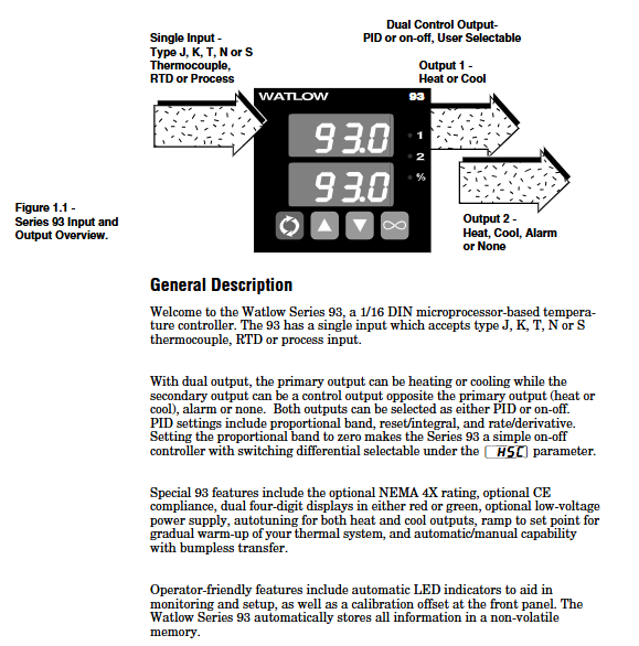
The Watlow Series 93 is a 1/16 DIN microprocessor based temperature controller with a single input dual output design. It supports J, K, T, N, S-type thermocouples, RTDs, or process signal (0-5V DC, 4-20mA) inputs, and outputs can be configured for heating, cooling, alarm, or shutdown functions. It has both PID and switch control modes and is suitable for industrial temperature control scenarios. The product complies with ISO 9001 standards, has an IP65 (NEMA 4X) protection level (optional), supports CE certification, provides a 3-year warranty, and is equipped with dual four digit red or green display screens by default, making it easy to operate.
Core functions and technical details
(1) Control mode and algorithm
PID control
Proportional band (Pb): The range can be set to 0-555 ° C (or ° F/unit), and it automatically switches to switch control when Pb=0; Under the SI unit, it is displayed in "% range" (0.0-999.9%), with a default value of 3%. The smaller the value, the higher the control sensitivity.
Integral/Reset (It/rE): Integral time 0.1-99.9 minutes/time (SI), reset frequency 0.01-99.9 times/minute (US), default 0, used to eliminate static deviation (droop) and avoid deviation from the set value after temperature stabilization.
Differential/Rate (dE/rA): 0.01-99.9 minutes, default 0, suppresses overshoot by predicting temperature trends, suitable for thermal systems with fast heating rates and high inertia.
Cycle time (Ct): 0.1-999.9 seconds, default 5 seconds. It is recommended to extend the cycle for mechanical relays to reduce contact wear, while solid-state relays can shorten the cycle to improve control accuracy.
Self tuning function
Trigger method: Set the [AUt] parameter in the operation menu (0=off, 1=slow, 2=medium, 3=fast), press the forward button to start, and after starting, the lower display screen will alternate between "[AUt]" and the current parameter.
Working principle: Based on 90% of the set value, the system's thermal characteristics are "learned" through 4 cross temperature points, and the optimal PID parameters are automatically calculated; If 4 crosses are not completed within 80 minutes, automatically exit and maintain the original parameters.
Applicable scenarios: Slow mode is suitable for scenarios where heating is slow and overshoot is not allowed (such as laboratory reactors), while fast mode is suitable for industrial heating furnaces and other scenarios where the set value needs to be quickly reached.
switch control
When the PID proportional band is set to 0, it is enabled, and the switching difference is defined by the [` HSC] parameter (1-55 ° C/1-99 ° F, default 2 ° C/3 ° F). When the temperature is below the set value - difference, the output is turned on, and when it is above the set value+difference, the output is turned off. It is suitable for scenarios with low control accuracy requirements (such as warehouse insulation).
(2) Alarm and safety functions
Alarm type configuration
**Process alarm ([PrA]/[Pr]) * *: Based on absolute temperature triggering, [ALO] (low alarm threshold, default range low limit) and [AHI] (high alarm threshold, default range high limit) need to be set in the operation menu. [PrA] will flash the alarm information, and [Pr] will only trigger the output without display.
**Deviation alarm (dEA/dE) * *: triggered based on the deviation of the set value, [ALO] range -999-0 (deviation below the set value), [AHI] range 0-999 (deviation above the set value), the alarm threshold automatically follows when the set value changes (e.g. set value of 100 ° F, deviation+7 ° F, alarm trigger point is 107 ° F).
Alarm auxiliary function
**Locked ([LAt]) * *: [LAt] (locked) needs to be manually cleared by pressing the infinite key, [` nLA] (non locked) will automatically clear when the temperature returns to the safe range, default is non locked.
**Silent (SIL) * *: Only deviation alarm is supported. When set to "On", press the infinite key to activate the alarm output when powered on. Even if the temperature exceeds the difference after activation, the alarm output will remain closed until the temperature returns to the safe range and the triggering ability is restored.
Hysteresis (HSA): 1-5555 ° C (or ° F/unit), default 2 ° C/3 ° F, to avoid frequent alarms caused by temperature fluctuations near the alarm threshold (e.g. alarm threshold of 100 ° C, hysteresis of 2 ° C, temperature drops below 98 ° C before the alarm is released).
(3) Auxiliary control function
Slope heating (rP)
Supports two modes: [Str] (only slopes from the current temperature to the set value when powered on), [On] (also slopes when the set value changes), with a ramp rate range of 0-9999 °/hour (default 100 °/hour), and the lower display screen alternately flashes "rP" and the target set value during the ramp process.
Applicable scenarios: To avoid damage to heating elements due to instantaneous high temperatures (such as glass melting furnaces), and to prevent deformation of workpieces due to excessive temperature differences (such as metal heat treatment).
Power Limit ([PL])
Only heating output is available, with a range of 0-100% (default 100%), limiting the maximum power of heating output to avoid load overload (such as when a small heater is adapted to a high-power controller, power should be limited to prevent burnout).
Calibration offset (CAL)
Range ± 100 ° C/± 180 ° F (or ± 180 units), default 0, used to compensate for measurement deviations caused by sensor installation errors or environmental interference (if the sensor is installed in a heat dissipation area and the actual temperature is 5 ° C higher than the measured value, a+5 ° C offset can be set).
Automatic/manual undisturbed switching
Switching mode: Press the infinite key twice to enter manual mode, the percentage indicator light remains on, and the lower display screen shows the output power (-100% to 100%, negative sign represents cooling); Press the infinite key again to return to automatic mode.
Non disruptive logic: When switching from automatic to manual mode, the output power remains at the PID calculated value before switching; When manually switching to automatic mode, transition to PID control starting from the current manual power to avoid sudden temperature changes.
Sensor fault handling: When the lock level [LOC] is 0/1/2, the sensor will automatically switch to manual mode after an open circuit (maintain the power before the fault, set to 0% if the power is unstable); Directly turn off the output at level 3/4.
Installation and wiring specifications
(1) Installation process
Panel preparation: Cut according to the size of 44.96-45.47mm (width x height). It is recommended to use Greenlee 60287 type 1/16 DIN punch, with a panel thickness of 1.5-9.7mm. When installing multiple units, the distance between adjacent cuts should be ≥ 20mm (to avoid heat dissipation interference).
Sealed installation (IP65 model):
Confirm that the housing gasket (circular with rounded corners) is facing the panel, without distortion or damage, and is embedded in the groove of the housing frame.
Insert the controller into the incision, press the panel side shell, insert the installation ring from the back, ensure that the installation ring buckle is aligned with the shell protrusion, press the buckle with your thumb until you hear a "click" sound, and check that the distance between the panel and the shell is ≤ 0.483mm (ensure sealing).
Dismantling method: Use a thin screwdriver or putty knife to gently pry open the 6 buckles of the installation ring, detach them one by one, and then shake the installation ring back and forth to remove it, avoiding pulling and damaging the shell with force.
(2) Wiring Details
Power wiring
High voltage type (93_ -1 0-00): Terminal 11 is connected to L1 (100-240V AC, actually compatible with 85-264V), terminal 12 is connected to L2, built-in 1A slow melting fuse (250V), cannot be replaced with fast melting fuse.
Low voltage type (93_ -1 1-00 _): Terminal 11 is connected to positive (12-24V AC/DC, actually compatible with 10-26V), terminal 12 is connected to negative, with built-in 2A slow melting fuse. It is strictly prohibited to connect high voltage (which may cause irreversible damage).
Input wiring
Thermocouple: Terminal 3 is connected to the positive pole (if the red color of the J-type thermocouple is negative, pay attention to the polarity), terminal 5 is connected to the negative pole, and the extension wire should be made of the same material as the thermocouple (if the J-type thermocouple uses iron constantan material) to avoid errors; If the external device is not isolated, an isolated thermocouple should be used.
3-wire RTD: Terminal 2 is connected to S1, Terminal 3 is connected to S2, and Terminal 5 is connected to S3. The three leads must have the same specifications (same wire diameter and length), and the total lead resistance should be ≤ 20 Ω to avoid measurement errors caused by resistance differences; 2-wire RTD requires short circuiting terminals 3 and 5, resulting in low accuracy (+2 ° F error per 1 Ω lead resistance).
4-20mA signal: Terminal 2 is connected to the negative pole, terminal 5 is connected to the positive pole, and the input impedance is 5 Ω. It is necessary to ensure that the signal source and controller are grounded together to avoid grounding loops.
Output wiring
Mechanical relay (Output 1: Terminals 8/9/10): Terminal 8 is normally closed (NC), 9 is common terminal (COM), 10 is normally open (NO), maximum load 5A@240V Communication, inductive loads (such as relay coils) require parallel RC suppressors (Watlow 0804-0147-0000), minimum load 100mA@5V DC (to avoid contact oxidation).
4-20mA output (Output 1: Terminal 9/10): Terminal 9 is connected to the positive pole and 10 to the negative pole, with a maximum load impedance of 800 Ω. It is used to control actuators such as frequency converters and valves. Shielded wire is required for wiring, and the shielding layer is grounded at one end (controller end).
Safety Specifications
All wiring must comply with NEC and local electrical standards, with wire diameter of 20-14AWG and terminal torque of 1.4Nm (12in lb), to avoid poor contact caused by looseness and damage to terminals caused by tightness.
Disassembling the controller after power failure may result in residual voltage at the casing terminals, and insulated gloves should be worn during operation; When installing in high temperature environments, insulation pads should be added between the controller and the heat source to avoid ambient temperatures exceeding 65 ° C (rated operating limit).
Menu Configuration and Operation Guide
(1) Menu Structure
Menu Type Entry Method Core Parameter Function Description
Long press the up and down arrow keys for 3 seconds in the Setup menu, and the lower display will show "['LOC]" [LOC] [Lock Level], [In] (Input Type), [rL]/[rH] (Range), [Ot1]/[Ot2] (Output Mode), [HSC] (Switch Difference), [LAt] (Alarm Lockout). Configure the controller hardware logic, input and output basic parameters, and some parameters (such as [In]) will be reset to factory default values after modification
Press the forward button in the Operation menu to display parameters [Pb1]/[Pb2] (proportional band), [It1]/[rE1] (integral/reset), [dE1]/[rA1] (differential/rate), [ALO]/[AHI] (alarm threshold), [AUT] (self-tuning), [CAL] (calibration offset) in sequence. Real time adjustment of control parameters, start self-tuning, set alarm threshold, and automatically save 5 seconds after parameter modification
Calibration menu: Long press the up and down arrow keys from the settings menu. The lower part displays "[CAL]", and the upper part is set to "[YES]". [000] (0mV input calibration), [500] (50mV input calibration), [440] (44.01 Ω RTD calibration), [rSt] (factory calibration restored). To calibrate the input/output accuracy, professional equipment (such as precision millivolt sources, resistance boxes) is required. The output is turned off during calibration
(2) Key parameter configuration steps
Input type configuration
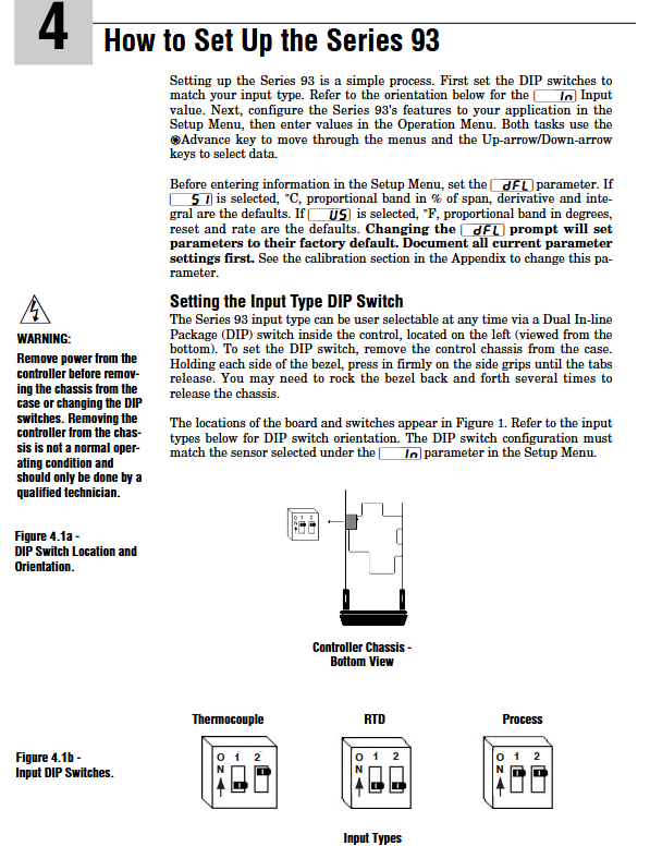
Open the controller chassis (press the buckles on both sides of the panel to remove it), and set the left DIP switch (8 positions) according to the input type: set the thermocouple to "O N", the RTD to "N O", and the process signal to "O O" (refer to Figure 4.1b for details).
Enter the settings menu and set the [In] parameter (such as setting the J-type thermocouple to "[J]" and the 100 Ω RTD to "[rtd]"), ensuring consistency with the DIP switch, otherwise an error of "[Er7]" will be displayed.
PID parameter self-tuning
Enter the operation menu, set [AUt] to 2 (medium response), press the forward button to start, the controller enters switch control mode (output full power), and starts "learning" when the temperature approaches 90% of the set value.
After self-tuning is completed, [AUt] automatically resets to 0, and the PID parameters ([Pb1]/[It1]/[dE1]) are updated to their optimal values. If manual fine-tuning is required, it can be modified in the operation menu.
Alarm configuration (deviation alarm as an example)
Setting menu: [Ot2] set to "[dEA]" (with display), [SIL] set to "[` On]" (mute enabled), [HSA `] set to "5" (5 ° C lag).
Operation menu: Set [ALO] to "-10" (alarm for temperatures below the set value of 10 ° C), set [AHI] to "+10" (alarm for temperatures above the set value of 10 ° C), lower will flash "[LO]"/"[HI]" when the temperature exceeds the set value, press the infinite key to clear.
(3) Display and button operation
Display screen function
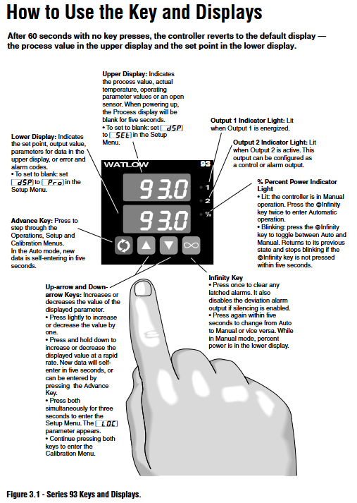
Upper display screen: default display process value (PV), parameter value is displayed during parameter configuration, "[---]" is displayed when the sensor fails, and an error code (such as "[Er7]") is displayed when the infinite key is pressed twice.
Lower display screen: By default, the set value (SP) is displayed. When configuring parameters, the parameter name (such as "[Pb1]") is displayed. When an alarm is triggered, the alarm type flashes. In manual mode, the output power (such as "50%") is displayed.
Indicator lights: Output 1/2 indicator light (red) on indicates output activation, percentage indicator light (green) constantly on indicates manual mode, flashing indicates mode to be switched.
Shortcut key operation
Return to default display: Press and hold the infinite key for 2 seconds, regardless of the current menu, directly return to PV/SP display.
Clear alarm: After the alarm is triggered, press the infinite key once to clear the locking alarm (the temperature needs to return to the safe range).
Quickly enter the settings menu: Long press the up and down arrow keys on any interface for 3 seconds to directly enter the [LOC] parameter.
Troubleshooting and Maintenance
(1) Common Error Handling
Steps for handling error code reasons
[Er2] RTD input below -200 ° C (or sensor failure) 1. Check if the RTD wiring is loose or broken; 2. Measure the RTD resistance with a multimeter and confirm that it is within the normal range (such as 100 Ω at 0 ° C); 3. If the resistance is normal, enter the calibration menu to perform RTD calibration
[Er4] microprocessor configuration error 1. Power off and restart, observe if it is restored; 2. If it repeatedly occurs, contact Watlow technical support (provide model and fault frequency); 3. Chassis cannot be disassembled by oneself to avoid warranty expiration
[Er5] Non volatile memory verification error: 1. Power off and restart after 30 seconds to eliminate transient interference; 2. Enter the calibration menu and execute [rSt] (restore factory calibration); 3. If it is ineffective, it needs to be returned to the factory for repair (memory damage)
[Er6]/[Er7] Analog to digital conversion undercurrent/overflow (sensor open circuit, polarity reversed) 1. Check sensor wiring: thermocouple confirms polarity, RTD confirms lead resistance, process signal confirms signal source; After replacing the sensor, press the forward button to clear the error; 3. If the wiring is normal, check if the DIP switch matches the In parameter
(2) Daily maintenance
regular maintenance
Check monthly whether the wiring terminals are loose (especially in vibration environments), whether the sealing gasket is aging (IP65 model), and whether the sensor probe is scaled (affecting temperature measurement accuracy).
Calibrate once every quarter: Use a precision temperature source (such as a dry furnace) to simulate the standard temperature. If the measurement deviation exceeds ± 1 ° C, enter the calibration menu to adjust the [CAL] parameter (if the actual temperature is 200 ° C, it displays 198 ° C and is set to+2 ° C).
- OMRON
- ABB
- General Electric
- EMERSON
- Honeywell
- HIMA
- ALSTOM
- Rolls-Royce
- MOTOROLA
- Rockwell
- Siemens
- Woodward
- YOKOGAWA
- FOXBORO
- KOLLMORGEN
- MOOG
- KB
- YAMAHA
- BENDER
- TEKTRONIX
- Westinghouse
- AMAT
- AB
- XYCOM
- Yaskawa
- B&R
- Schneider
- KONGSBERG
- NI
- WATLOW
- ProSoft
- SEW
- ADVANCED
- Reliance
- TRICONEX
- METSO
- MAN
- Advantest
- STUDER
- DANAHER MOTION
- Bently
- Galil
- EATON
- MOLEX
- DEIF
- B&W
- ZYGO
- Aerotech
- DANFOSS
- Beijer
- Moxa
- Rexroth
- Johnson
- WAGO
- TOSHIBA
- BMCM
- SMC
- HITACHI
- HIRSCHMANN
- Application field
- XP POWER
- CTI
- TRICON
- STOBER
- Thinklogical
- Horner Automation
- Meggitt
- Fanuc
- Baldor
- SHINKAWA
- Other Brands
- UniOP
- KUKA
- Iba
- Beckhoff
-
 Basler DECS-100-B15 Digital AVR
 -
 Basler 9284900103 PS DECS-400N
 -
 Basler D4N3H1U Intertie Protection
 -
 Basler DECS-100-B15 A15 AVR
 -
 Basler KR4F Voltage Regulator
 -
 Basler BE26434 T14 Transformer
 -
 Basler SR8A-2B15B3A Regulator
 -
 Westinghouse 774B472A12 AR Relay
 -
Basler DECS-100-B15 AVR
-
 Basler XR2002F Regulator 110V
 -
 Basler SR125-E Static Regulator
 -
 Basler SSR 125-12 Regulator
 -
 Basler MOC2599 Motor Pot
 -
 Basler BE1-DFPR Feeder Relay
 -
 Basler CBS 305 Current Boost
 -
 Basler BE1-25 AutoSync
 -
 Basler MVC 300 Voltage Control
 -
 Basler BE3-25A AutoSync
 -
 Basler KR7FF Static Regulator
 -
 Basler 90-49000-100 Regulator
 -
 Basler 880 kVA Dry Type Transformer Specs
 -
 Basler Electric BE1-25 Sync-Check Relay Specs
 -
 Basler SSR 125-12 Voltage Regulator Specs
 -
 Basler Electric BE1-851 Overcurrent Relay Review
 -
Basler Electric 149D930G02 Control Sub-Assembly
-
 Basler Electric BE1-81O/UT Frequency Relay Specs
 -
 Basler Electric BE1-51/27C Overcurrent Relay
 -
 Basler Electric 149D956G02 Industrial Component
 -
Basler Electric BE1-51A Overcurrent Relay Specs
-
 Basler Electric BE1-40Q Loss of Excitation Relay
 -
 Basler DECS-200 Excitation Control System
 -
 Basler DECS-200 Voltage Regulator 56-277V AC / 125V DC
 -
 Basler BE1-87T Transformer Differential Relay
 -
 Basler RDP-110-S1 Protection Relay
 -
 Basler BE1-700V Digital Protective Relay
 -
 Basler BE1-951 Overcurrent Protection System
 -
 Basler DECS-300 Digital Excitation Control
 -
 Basler DECS-200 Digital Excitation Control
 -
 Basler DECS-200-1C Excitation Control System
 -
Basler DECS-200-1L Digital Excitation Control
-
 Basler Electric BE1-GPS Generator Protection System
 -
Basler Electric DECS-200-1C Digital Excitation Controller
-
 Basler Electric DECS125-15 Excitation Control with Power Module
 -
 Basler Electric BE1-87G Differential Relay
 -
 Basler Electric BE1-11 Protection System I5A3M2P2N0EA00
 -
Basler Electric DECS-200-1C Excitation Control System
-
Basler Electric BE1-11g Generator Protection Relay
-
 Basler Electric DECS 125-15-B2C1 V2.0.9 Excitation Control
 -
 Basler Electric BE1-81O/UT3ED1JA7N2F Frequency Relay
 -
Basler Electric BE1-81O/UT3EE1YB7N1F Frequency Relay
-
 Basler Electric DECS-200-1L Digital Excitation Control System
 -
Basler DECS125-15-B2C1 Excitation Control
-
 Basler 9507900205 SSR Retrofit Voltage Regulator
 -
 Basler BE2000E Digital Voltage Regulator
 -
 Basler BE1-GPS Generator Protection System
 -
Basler DECS-250-CN1CN1N Digital Excitation Control
-
 Basler DGC-2020 Genset Controller
 -
 Basler BE1-81O UT3ED1LA7N0F Frequency Relay (Variant)
 -
 Basler BE1-81O UT3EE1YA9S0F Frequency Relay (Variant)
 -
Basler BE1-81O Over/Under Frequency Relay
-
Basler DECS125-15 Digital Excitation Control
-
Basler Electric BE1-951 Overcurrent Protection System
-
 Basler Electric BE1-700V Digital Protective Relay
 -
 Basler Electric APR63-5 Automatic Voltage Regulator
 -
Basler Electric BE1-851 Overcurrent Protection System
-
Basler Electric DECS-250-LN1SN1N Excitation Control
-
 Basler Electric BE1-87T Transformer Differential Relay
 -
Basler Electric DECS-200-1L Excitation Control System
-
 Basler Electric 9310300100 DECS-300 Excitation Control
 -
 Basler Electric SSE-N 125-4.5KW Shunt Exciter Regulator
 -
 Basler Electric DGC-2020HD-5NS1DNSBA Genset Controller
 -
Basler Electric BE1-81-O/UT3EE1JB7N1F Frequency Relay
-
Basler Electric BE1-81T1EE1WA0N1F Frequency Relay
-
 Basler Electric BE1-25M1EA6PN5R1F Sync-Check Relay
 -
 Basler Electric BE1-GPS Generator Protection System
 -
Basler Electric DECS-250-LN1SN1N Excitation Control Rev V
-
 Basler Electric DECS-250-CN2CN1N Excitation Control
 -
Basler Electric BE1-50/51B-207 Overcurrent Relay
-
Basler Electric DECS-300-C0N0 Excitation Control System
-
Basler Electric DECS-200 Digital Excitation Control System
-
Basler Electric DECS-250-LN1CN1N Excitation Unit
-
Basler Electric DECS-250 LN2SA1D Excitation Unit Specs
-
Basler Electric BE1-87T Transformer Relay Review
-
Basler Electric BE1-11 Protection System
-
Basler Electric BE1-GPS100-E4N1H1N Protection System
-
 Allen-Bradley 442G-MABH-R Safety Module
 -
 Beckhoff CX1030-0111 PLC Assembly Profile
 -
 FANUC IC693CPU364 PLC Module
 -
 Orange Denmark Type 200816 220 PLC Specs
 -
 OMRON C200H-SNT31 Sysmac PLC Module
 -
 Allen Bradley 20AB022A3AYNANC0 PowerFlex 70
 -
 OMRON C200HW-PCU01 Position Control Unit
 -
 ABB AO845A-eA Analog Output Module
 -
 OMRON CJ1M-CPU22 CPU Unit
 -
 Allen Bradley 100-E265ED11 Contactor
 -
 Honeywell 51304511-100 Interface Module
 -
 SOLEXY BXF3S0101N0018 Gateway Module
 -
 OMRON CJ2H-CPU65 CPU Unit
 -
 Automation Direct GS2-45P0 AC Drive
 -
 M68-2000 2-Axis Motion CNC Controller
 -
 OMRON CJ1M-CPU11 V3.0 PLC CPU Unit
 -
 OMRON CJ1W-NC413 4-Axis Positioning Controller
 -
 OMRON 3G2A3-PRO16 Programming Console HMI
 -
 Siemens 3VT8440-2AA04-2GA2 Molded Case Circuit Breaker
 -
 Siemens 3RT5045 Contactor Series
 -
 OMRON C200HS-CPU01-E SYSMAC PLC Controller
 -
 OMRON C500-NC103-E Positioning Control Unit
 -
 OMRON CJ1W-TC001 Temperature Control Unit
 -
 OMRON NJ301-1100 NJ-PA3001 PLC System EtherCAT
 -
 Pilz 773100 M1P Safety Relay Base Unit
 -
 Siemens SINUMERIK 840D SL NCU 720.3B with PLC 317-3 PN/DP
 -
 Siemens 6AV6618-7GD01-3AB0 HMI Panel
 -
 OMRON F150-C15E-3 Vision Mate Controller PLC Overview
 -
 Mitsubishi MELSEC A Series PLC System A63P A3ACPU A616AD A68RD3
 -
 M68-2000 2 Axis Motion Controller SCE SERVO CNC
 -
 OMRON FZ-S2M PLC Camera Vision System
 -
 VISOLUX SLVA-4K PLC Module from Elektronik GmbH
 -
 OMRON CJ1M-CPU23 V2.0 PLC CPU Unit
 -
 ABB AI86-16CHF PCB Card 5761751-9 B Specifications
 -
 Allen-Bradley 100-D140ZJ22L Contactor Overview
 -
 Merlin Gerin PB80 PLC Rack
 -
 WEIR WE203 Power Supply PLC
 -
 OMRON NX-TS3102 Temperature Input Unit
 -
 Siemens 6ES7146-6FF00-0AB0 I/O Module
 -
 Fanuc A16B-3300-0057 Circuit Board
 -
 OMRON CJ1W-IDP01 Input Module
 -
 Siemens 6FX2007-1AD13 Handheld Unit
 -
 Gems EM54 PLC Module PCB


