
Watlow Series 96 Temperature Controller
Process signal: 4-20mA signal connected to+R1/- S1 terminal (input impedance of 100 Ω), 0-10V signal connected to+T1/- S1 terminal (input impedance of 20k Ω), requiring separate shielded wiring.
Output and communication wiring
Relay output (D-type): When connecting to an AC load, an RC suppressor (Watlow model 0804-0147-0000) should be connected in series to avoid arcing damage to the contacts due to power failure of inductive loads.
Communication wiring: EIA-485 uses twisted pair cables, with T+/R+connected to terminal B and T -/R - connected to terminal A. A 120 Ω terminal resistor needs to be added at the end of the bus, and it can support up to 32 devices in a network (with extension relays up to 247).
Event input: The dry contact is connected to the EVENT+/- terminal, with an active state resistance of<2k Ω and an inactive state resistance of>23k Ω. The voltage input supports 3-36V DC, with an active state resistance of>3V and an inactive state resistance of<2V.

Operating interface and core functions
(1) User interface
Keys and Display
Key functions: up/down arrow keys (parameter adjustment/menu scrolling), forward key (confirm/enter submenu), infinite key (return to home page/start/pause curve).
Display mode: The process value/error code is displayed on the upper screen, and the set value/parameter name is displayed on the lower screen. The indicator lights include output activation (1-4), manual mode (%), and profile mode.
Custom menu: Press and hold the forward key+infinite key for 6 seconds to enter the factory page, where you can add commonly used parameters (such as set points, PID parameters, alarm thresholds), up to 16 items, for quick access without the need for layer by layer navigation.
Menu Structure
Home Page: Display process values and set points, allowing for direct adjustment of commonly used parameters.
Operations page: including monitoring, users PID1/2、 Alarm menu, configurable control mode, automatic setting, alarm threshold.
Setup page: Configure input types, output functions, global parameters (units, fault modes, etc.).
Factory page: Customize menu, lock, diagnostic, calibration functions (permission required).
(2) Core function operation
PID control and automatic tuning
Automatic tuning: Enter "Operations - Auto tune" and select "tune". The controller aims to achieve 90% of the current set point and calculates the optimal PID parameters by crossing the target value multiple times. During the tuning period, it outputs 100% power and ensures load safety.
Control mode switching: On Off control (proportional band set to 0), PI/PID control (adjusting proportional band/integral/derivative parameters), in dual PID mode, output 1 corresponds to heating, output 2 corresponds to cooling, and a dead zone can be set to avoid antagonism.
Burst Fire: Suitable for resistive loads, reduces electromagnetic interference (RFI) through zero crossing switching, requires the "Burst" function to be enabled in the PID menu, with a cycle time of 0.1-60 seconds.
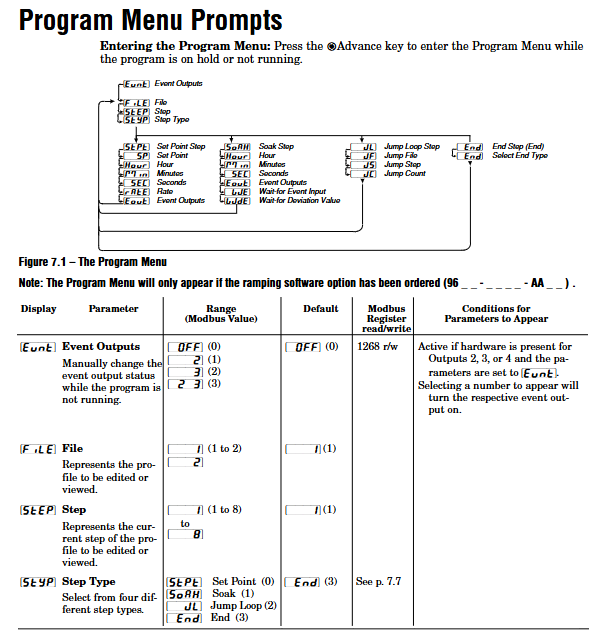
Curve Programming (Ramp/Soak)
Curve configuration: Supports 2 files (File1/File2), with 8 steps per file. The step types include Set Point, Soak, Jump Loop, and End. Event output can be set (such as starting an external device).
Operation: Press the infinite key from the homepage to enter the pre run menu, select the file and start steps, and then press the infinite key to start; Press the infinite key to pause during operation, and the pause step can be restored through the "resU" parameter.
Waiting function: The insulation step supports "Wait for Event" (event input trigger) and "Wait for Deviation" (process value entering deviation zone trigger), and timing can only start after meeting the conditions.
Alarm and fault handling
Alarm configuration: 4-channel alarms can be set as process alarms (fixed threshold) or deviation alarms (relative to the set point), supporting high/low alarms, locking/non locking, and mute functions. Hysteresis can be set to 1-9999 units to avoid false triggering.
Fault diagnosis: Input error (sensor open circuit/over range), system error (RAM/ROM fault), open-loop detection (100% output without process value change), locate the problem through the error code on the display screen (such as Err1-Err16), refer to the appendix for troubleshooting.
Fault mode: When the sensor fails, it can be set to Bumpless, Manual mode, or Off output mode. Bumpless switching can maintain the output power before the fault and avoid process fluctuations.
Communication and Remote Configuration
(1) Communication parameter settings
Protocol and hardware: Supports Modbus RTU protocol, optional EIA-232 (model including "R") or EIA-485 (model including "U") communication module, wiring needs to distinguish T+/R+/T -/R-terminals.
Configuration steps: Enter "Setup - Output4- Baud Rate" to set the baud rate (1200/2400/4800/9600/19200), and set the device address (1-247) in "Address" to ensure consistency with the parameters of the upper computer (PLC/PC).
Data retransmission: Output 4 can be configured as a retransmission function (model includes "M"), supporting retransmission process values, setpoints, or output power. The signal range is calibrated through "Scale Low/High" and "Range Low/High" (such as 4-20mA corresponding to 0-100 ° C).
- OMRON
- ABB
- General Electric
- EMERSON
- Honeywell
- HIMA
- ALSTOM
- Rolls-Royce
- MOTOROLA
- Rockwell
- Siemens
- Woodward
- YOKOGAWA
- FOXBORO
- KOLLMORGEN
- MOOG
- KB
- YAMAHA
- BENDER
- TEKTRONIX
- Westinghouse
- AMAT
- AB
- XYCOM
- Yaskawa
- B&R
- Schneider
- KONGSBERG
- NI
- WATLOW
- ProSoft
- SEW
- ADVANCED
- Reliance
- TRICONEX
- METSO
- MAN
- Advantest
- STUDER
- DANAHER MOTION
- Bently
- Galil
- EATON
- MOLEX
- DEIF
- B&W
- ZYGO
- Aerotech
- DANFOSS
- Beijer
- Moxa
- Rexroth
- Johnson
- WAGO
- TOSHIBA
- BMCM
- SMC
- HITACHI
- HIRSCHMANN
- Application field
- XP POWER
- CTI
- TRICON
- STOBER
- Thinklogical
- Horner Automation
- Meggitt
- Fanuc
- Baldor
- SHINKAWA
- Other Brands
- UniOP
- KUKA
- Iba
- Beckhoff
-
 Basler Electric DECS-200-1L Digital Excitation Control System
 -
 Basler DECS125-15-B2C1 Excitation Control
 -
 Basler 9507900205 SSR Retrofit Voltage Regulator
 -
 Basler BE2000E Digital Voltage Regulator
 -
 Basler BE1-GPS Generator Protection System
 -
 Basler DECS-250-CN1CN1N Digital Excitation Control
 -
 Basler DGC-2020 Genset Controller
 -
 Basler BE1-81O UT3ED1LA7N0F Frequency Relay (Variant)
 -
 Basler BE1-81O UT3EE1YA9S0F Frequency Relay (Variant)
 -
 Basler BE1-81O Over/Under Frequency Relay
 -
 Basler DECS125-15 Digital Excitation Control
 -
 Basler Electric BE1-951 Overcurrent Protection System
 -
 Basler Electric BE1-700V Digital Protective Relay
 -
 Basler Electric APR63-5 Automatic Voltage Regulator
 -
 Basler Electric BE1-851 Overcurrent Protection System
 -
 Basler Electric DECS-250-LN1SN1N Excitation Control
 -
 Basler Electric BE1-87T Transformer Differential Relay
 -
 Basler Electric DECS-200-1L Excitation Control System
 -
 Basler Electric 9310300100 DECS-300 Excitation Control
 -
 Basler Electric SSE-N 125-4.5KW Shunt Exciter Regulator
 -
 Basler Electric DGC-2020HD-5NS1DNSBA Genset Controller
 -
Basler Electric BE1-81-O/UT3EE1JB7N1F Frequency Relay
-
 Basler Electric BE1-81T1EE1WA0N1F Frequency Relay
 -
 Basler Electric BE1-25M1EA6PN5R1F Sync-Check Relay
 -
 Basler Electric BE1-GPS Generator Protection System
 -
Basler Electric DECS-250-LN1SN1N Excitation Control Rev V
-
 Basler Electric DECS-250-CN2CN1N Excitation Control
 -
 Basler Electric BE1-50/51B-207 Overcurrent Relay
 -
Basler Electric DECS-300-C0N0 Excitation Control System
-
Basler Electric DECS-200 Digital Excitation Control System
-
Basler Electric DECS-250-LN1CN1N Excitation Unit
-
Basler Electric DECS-250 LN2SA1D Excitation Unit Specs
-
Basler Electric BE1-87T Transformer Relay Review
-
Basler Electric BE1-11 Protection System
-
Basler Electric BE1-GPS100-E4N1H1N Protection System
-
 Allen-Bradley 442G-MABH-R Safety Module
 -
 Beckhoff CX1030-0111 PLC Assembly Profile
 -
 FANUC IC693CPU364 PLC Module
 -
 Orange Denmark Type 200816 220 PLC Specs
 -
 OMRON C200H-SNT31 Sysmac PLC Module
 -
 Allen Bradley 20AB022A3AYNANC0 PowerFlex 70
 -
 OMRON C200HW-PCU01 Position Control Unit
 -
 ABB AO845A-eA Analog Output Module
 -
 OMRON CJ1M-CPU22 CPU Unit
 -
 Allen Bradley 100-E265ED11 Contactor
 -
 Honeywell 51304511-100 Interface Module
 -
 SOLEXY BXF3S0101N0018 Gateway Module
 -
 OMRON CJ2H-CPU65 CPU Unit
 -
 Automation Direct GS2-45P0 AC Drive
 -
 M68-2000 2-Axis Motion CNC Controller
 -
 OMRON CJ1M-CPU11 V3.0 PLC CPU Unit
 -
 OMRON CJ1W-NC413 4-Axis Positioning Controller
 -
 OMRON 3G2A3-PRO16 Programming Console HMI
 -
 Siemens 3VT8440-2AA04-2GA2 Molded Case Circuit Breaker
 -
 Siemens 3RT5045 Contactor Series
 -
 OMRON C200HS-CPU01-E SYSMAC PLC Controller
 -
 OMRON C500-NC103-E Positioning Control Unit
 -
 OMRON CJ1W-TC001 Temperature Control Unit
 -
 OMRON NJ301-1100 NJ-PA3001 PLC System EtherCAT
 -
 Pilz 773100 M1P Safety Relay Base Unit
 -
 Siemens SINUMERIK 840D SL NCU 720.3B with PLC 317-3 PN/DP
 -
 Siemens 6AV6618-7GD01-3AB0 HMI Panel
 -
 OMRON F150-C15E-3 Vision Mate Controller PLC Overview
 -
 Mitsubishi MELSEC A Series PLC System A63P A3ACPU A616AD A68RD3
 -
 M68-2000 2 Axis Motion Controller SCE SERVO CNC
 -
 OMRON FZ-S2M PLC Camera Vision System
 -
 VISOLUX SLVA-4K PLC Module from Elektronik GmbH
 -
 OMRON CJ1M-CPU23 V2.0 PLC CPU Unit
 -
 ABB AI86-16CHF PCB Card 5761751-9 B Specifications
 -
 Allen-Bradley 100-D140ZJ22L Contactor Overview
 -
 Merlin Gerin PB80 PLC Rack
 -
 WEIR WE203 Power Supply PLC
 -
 OMRON NX-TS3102 Temperature Input Unit
 -
 Siemens 6ES7146-6FF00-0AB0 I/O Module
 -
 Fanuc A16B-3300-0057 Circuit Board
 -
 OMRON CJ1W-IDP01 Input Module
 -
 Siemens 6FX2007-1AD13 Handheld Unit
 -
 Gems EM54 PLC Module PCB
 -
 Beckhoff CX2030-0121 Embedded PC CPU
 -
 OMRON NJ301-1100 Machine Automation Controller
 -
 Biesse Rover CNI PLC 2153 030 7146.30 Numerical Control Module
 -
 OMRON CJ1W DA08V Analog Output Module
 -
 OMRON CS1D ETN21D Ethernet Module
 -
 Allen Bradley 1768 L43 CompactLogix Controller
 -
 Schneider TWDLMDA40DTK Twido PLC Module
 -
 Mitsubishi NZ2EX2B 60AD4 Analog Input Module
 -
 OMRON NS8 TV00B V2 Touch Display Panel
 -
 Mitsubishi AY71 CMOS TTL Output Module
 -
 OMRON C500 CPU11 E Processor Module
 -
 OMRON CJ1W PTS51 Temperature Input Module
 -
 Siemens 6SL3100-1DE22-0AA1 600V DC Supply
 -
 OMRON CJ1M-CPU23 PLC CPU 9‑Pin Serial
 -
 Schlumberger IMT4N 24‑250VAC 48‑230VAC PLC Timer
 -
 OMRON CJ1M-CPU22 PLC CPU Unit V2.0
 -
 Allen‑Bradley 2711P-B7C6D2 Touch Screen PanelView
 -
 ADSP-2181KST-160 Analog Devices DSP IC Specs
 -
 Schneider LC1F400 400A Contactor Specifications
 -
 Yaskawa SGDH-10DE-OY 1kW 400V Servo Drive
 -
 Schneider TM262L10MESE8T M262 PLC 5ns Inst
 -
 Mitsubishi AA104VJ05 10.4in LCD Panel Specs
 -
 Allen Bradley 1761-L32BWA MicroLogix 1000 PLC
 -
 Siemens 6ES7431-7KF00-0AB0 Analog Input Module
 -
 Allen Bradley 1769-OB16 Output Module
 -
 Siemens 6ES7131-1BL12-0XB0 Input Module
 -
 Beckhoff EP7041-3002 EtherCAT Box Module
 -
 Siemens RK7243-2AA30-0XB0 Communication Module
 -
 Siemens 4AM5742-8DD40-0FA0 Transformer
 -
 Siemens 3TK2834-1BB40 Safety Relay
 -
 Brother BAS 311 Sewing Machine Circuit Board
 -
Yaskawa SGDH-10DE-OY Servo Driver
-
 OMRON C60H C6DR DE V1 Sysmac PLC
 -
 MITSUBISHI ELECTRIC A2ACPU21 S1 CPU Module
 -
 ABB BAILEY INNPM12 Network Process Module
 -
 HONEYWELL 620 0073C IPC PLC Module
 -
 Mitsubishi 15050 PR02B PLC Circuit Board
 -
 SIEMENS 6SY7000 0AC37 Drive Control Module
 -
 OMRON TJ2 ECT16 Traxial EtherCAT Controller
 -
 GE Fanuc IC698PSD300D Power Supply Module
 -
 Texas Instruments Series 505 16 Position Base
 -
 OMRON YASKAWA SGDH 10DE OY Servo Drive
 -
 Allen‑Bradley 440G-MT Safety Interlock Switch Specs
 -
 Rubycon PD27A 24V 8A Power Supply Module
 -
 SK-H1-GDB1-F11D PLC Gate Driver Board Kit
 -
 VIPA 441-4UA14 451-4UA14 PLC Module Rack
 -
 Mitsubishi FX5U-80MT ESS PLC Controller Specs
 -
 Mitsubishi Q64TCRTN Temperature PLC Module
 -
 GE 1C31170G Rev10 PLC Circuit Board Module
 -
 Schneider TWDLMDA40DTK PLC Controller Module


