
Watlow Series L Temperature Limiting Controller
(2) DIN rail installation (LF series)
Rail preparation: Confirm that the DIN rail complies with DIN 50022 standard (35mm × 7.5mm), and is installed on a flat surface inside the cabinet, away from heat sources such as frequency converters and contactors.
Buckle installation: Insert the upper hook of the controller into the upper edge of the guide rail, press the lower part of the controller until the lower buckle "clicks" to lock onto the lower edge of the guide rail (if unable to lock, check if the guide rail is bent, adjust and retry).
Disassembly method: Press the release button on the upper part of the controller, while pulling the lower part forward to disengage the buckle from the guide rail, and remove the controller (disconnect the power and wiring before disassembly).
2. Wiring specifications and safety requirements
(1) Preparation before wiring
Power off confirmation: Before wiring, all relevant power sources must be disconnected, and a multimeter must be used to confirm that there is no voltage to avoid electric shock.
Wire selection:
Power wire: 12-18 AWG copper wire, current carrying capacity ≥ controller maximum current (LF/LV ≤ 0.5A, LS ≤ 0.1A).
Sensor wires: Thermocouples use the same type of compensating wire (such as JX-HS-FF for J-type), RTDs use 3-core shielded wire (20-24 AWG), and the shielding layer is only grounded at the sensor end.
Output wire: Depending on the load current, an additional RC suppressor (Watlow P/N 08040147-0000) needs to be connected in series for inductive loads.
(2) Core wiring example (LF/LV single circuit protection)
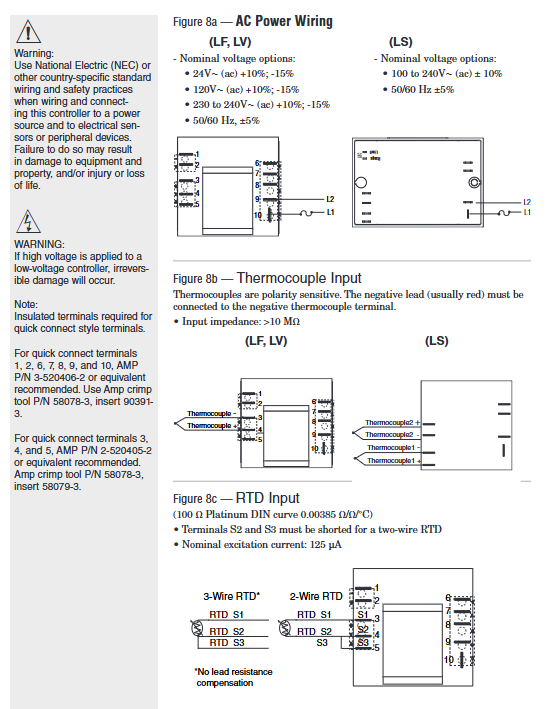
Power wiring: L1 (live wire) is connected to terminal 1, L2 (neutral wire) is connected to terminal 2, and a 2A slow melting fuse (250V) is connected in series. The live wire end needs to be connected to a circuit breaker (for easy power-off maintenance).
Sensor wiring (J-type thermocouple): The positive (non red) terminal of the thermocouple is connected to terminal 5, and the negative (red) terminal is connected to terminal 10. The extension wire needs to be a J-type compensating wire to avoid copper wires.
Output wiring: Relay COM terminal is connected to terminal 6, NO terminal is connected to one end of the contactor coil, and the other end of the coil is connected to L2; NC terminal is backup (can be connected to an alarm light), inductive load (contactor coil) is connected in parallel with an RC suppressor (between terminal 6 and NO terminal).
External reset wiring: One end of the external button is connected to terminal 9, and the other end is connected to terminal 6 (COM end). The button is of the instantaneous and constant on type (such as Schneider XB2-BA31).
(3) LS series dual sensor wiring
Power wiring: Connect L1 to terminal 1, L2 to terminal 2, and connect 2A slow melting fuses in series.
Dual sensor wiring (K-type thermocouple): Sensor 1 is connected to positive terminal 5 and negative terminal 10; The positive terminal of sensor 2 is connected to terminal 4, and the negative terminal is connected to terminal 9. The installation positions of the two sensors should be close (temperature difference ≤ 20 ° C).
Output wiring: The relay COM terminal is connected to terminal 6, and the NO terminal is connected to the heating tube power circuit. After triggering the protection, the NO terminal is disconnected, cutting off the heating tube power supply.
(4) Safety wiring requirements
Electrical isolation: Sensor cables, power cables, and output cables need to be wired separately (with a spacing of ≥ 10cm) to avoid electromagnetic interference; The grounding terminal of the controller (if any) needs to be connected to a protective ground (grounding resistance ≤ 4 Ω).
Installation in hazardous areas: Explosion proof junction boxes and armored cables are required for Class 1 Div. 2 hazardous areas, with terminal tightening torque ≥ 0.56 Nm, and live plug and unplug wiring is prohibited.
Anti misoperation wiring: strictly follow the terminal label for wiring, and do not reverse the positive and negative terminals of the power supply or the sensor (otherwise abnormal display or failure to trigger protection).
3. Analysis of Typical System Wiring Diagram (Industrial Oven Protection)
System composition: The main controller (Watlow Series CV) controls the temperature of the oven, while the LF series serves as redundant protection to prevent overheating caused by main controller failure.
Wiring logic:
The LF sensor and the main controller sensor are installed at different positions in the oven to avoid single point failures.
The LF output is connected in series with the main contactor coil circuit, and the main controller output is also connected in series with this circuit, forming a "double safety".
After triggering the LF protection, the contactor coil loses power, cutting off the power supply to the heating tube, and the ALARM light is on, requiring manual reset (or external button reset).
Troubleshooting and Maintenance
1. Common faults and solutions
Possible causes of malfunction, troubleshooting steps, and solutions
No display/action, ALARM light not on. 1. Power not connected or circuit breaker tripped
- OMRON
- ABB
- General Electric
- EMERSON
- Honeywell
- HIMA
- ALSTOM
- Rolls-Royce
- MOTOROLA
- Rockwell
- Siemens
- Woodward
- YOKOGAWA
- FOXBORO
- KOLLMORGEN
- MOOG
- KB
- YAMAHA
- BENDER
- TEKTRONIX
- Westinghouse
- AMAT
- AB
- XYCOM
- Yaskawa
- B&R
- Schneider
- KONGSBERG
- NI
- WATLOW
- ProSoft
- SEW
- ADVANCED
- Reliance
- TRICONEX
- METSO
- MAN
- Advantest
- STUDER
- DANAHER MOTION
- Bently
- Galil
- EATON
- MOLEX
- DEIF
- B&W
- ZYGO
- Aerotech
- DANFOSS
- Beijer
- Moxa
- Rexroth
- Johnson
- WAGO
- TOSHIBA
- BMCM
- SMC
- HITACHI
- HIRSCHMANN
- Application field
- XP POWER
- CTI
- TRICON
- STOBER
- Thinklogical
- Horner Automation
- Meggitt
- Fanuc
- Baldor
- SHINKAWA
- Other Brands
- UniOP
- KUKA
- Iba
- Beckhoff
-
 Basler D90 96801 100 PCB Card
 -
 Basler XR2002F Voltage Regulator (110 VAC, 48-480 Hz)
 -
 Basler SR8A-2B14B3A Regulator
 -
 Basler 9561500100 Module
 -
 Basler DECS-400 BE1-11 System
 -
 Basler DECS-100-B15 Excitation Control
 -
 Basler SCP 210 Frequency Controller
 -
 Basler SR4A-2B15B3A Static Voltage Regulator
 -
 Basler BE1-32R Power Relay
 -
 Basler PIA2400-17GM Power Interface Adapter
 -
 Basler MVC 232 Manual Voltage Control Module
 -
 Basler SSR 32-12 Static Voltage Regulator
 -
 Basler 5MW AVR Generator Voltage Regulator
 -
 Basler VR63-4B Voltage Regulator
 -
 Basler DECS-100-A05 AVR for Engine Generator
 -
 Basler DECS-100-B15 Automatic Voltage Regulator
 -
 Basler BE1-32R Directional Power Relay
 -
 Basler BE1-87B Differential Relay
 -
 Basler UFOV 260A Protective Module
 -
 Basler 9-2614-02-100 PCB Rev M
 -
Basler DECS-100-B15 Digital AVR
-
 Basler 9284900103 PS DECS-400N
 -
 Basler D4N3H1U Intertie Protection
 -
 Basler DECS-100-B15 A15 AVR
 -
 Basler KR4F Voltage Regulator
 -
 Basler BE26434 T14 Transformer
 -
 Basler SR8A-2B15B3A Regulator
 -
 Westinghouse 774B472A12 AR Relay
 -
Basler DECS-100-B15 AVR
-
Basler XR2002F Regulator 110V
-
Basler SR125-E Static Regulator
-
 Basler SSR 125-12 Regulator
 -
 Basler MOC2599 Motor Pot
 -
 Basler BE1-DFPR Feeder Relay
 -
 Basler CBS 305 Current Boost
 -
 Basler BE1-25 AutoSync
 -
 Basler MVC 300 Voltage Control
 -
 Basler BE3-25A AutoSync
 -
 Basler KR7FF Static Regulator
 -
 Basler 90-49000-100 Regulator
 -
 Basler 880 kVA Dry Type Transformer Specs
 -
 Basler Electric BE1-25 Sync-Check Relay Specs
 -
 Basler SSR 125-12 Voltage Regulator Specs
 -
 Basler Electric BE1-851 Overcurrent Relay Review
 -
Basler Electric 149D930G02 Control Sub-Assembly
-
 Basler Electric BE1-81O/UT Frequency Relay Specs
 -
 Basler Electric BE1-51/27C Overcurrent Relay
 -
 Basler Electric 149D956G02 Industrial Component
 -
Basler Electric BE1-51A Overcurrent Relay Specs
-
 Basler Electric BE1-40Q Loss of Excitation Relay
 -
 Basler DECS-200 Excitation Control System
 -
 Basler DECS-200 Voltage Regulator 56-277V AC / 125V DC
 -
Basler BE1-87T Transformer Differential Relay
-
 Basler RDP-110-S1 Protection Relay
 -
 Basler BE1-700V Digital Protective Relay
 -
 Basler BE1-951 Overcurrent Protection System
 -
 Basler DECS-300 Digital Excitation Control
 -
 Basler DECS-200 Digital Excitation Control
 -
 Basler DECS-200-1C Excitation Control System
 -
Basler DECS-200-1L Digital Excitation Control
-
 Basler Electric BE1-GPS Generator Protection System
 -
Basler Electric DECS-200-1C Digital Excitation Controller
-
 Basler Electric DECS125-15 Excitation Control with Power Module
 -
 Basler Electric BE1-87G Differential Relay
 -
 Basler Electric BE1-11 Protection System I5A3M2P2N0EA00
 -
Basler Electric DECS-200-1C Excitation Control System
-
Basler Electric BE1-11g Generator Protection Relay
-
Basler Electric DECS 125-15-B2C1 V2.0.9 Excitation Control
-
 Basler Electric BE1-81O/UT3ED1JA7N2F Frequency Relay
 -
Basler Electric BE1-81O/UT3EE1YB7N1F Frequency Relay
-
 Basler Electric DECS-200-1L Digital Excitation Control System
 -
Basler DECS125-15-B2C1 Excitation Control
-
 Basler 9507900205 SSR Retrofit Voltage Regulator
 -
 Basler BE2000E Digital Voltage Regulator
 -
 Basler BE1-GPS Generator Protection System
 -
Basler DECS-250-CN1CN1N Digital Excitation Control
-
 Basler DGC-2020 Genset Controller
 -
 Basler BE1-81O UT3ED1LA7N0F Frequency Relay (Variant)
 -
 Basler BE1-81O UT3EE1YA9S0F Frequency Relay (Variant)
 -
Basler BE1-81O Over/Under Frequency Relay
-
Basler DECS125-15 Digital Excitation Control
-
Basler Electric BE1-951 Overcurrent Protection System
-
 Basler Electric BE1-700V Digital Protective Relay
 -
 Basler Electric APR63-5 Automatic Voltage Regulator
 -
Basler Electric BE1-851 Overcurrent Protection System
-
Basler Electric DECS-250-LN1SN1N Excitation Control
-
 Basler Electric BE1-87T Transformer Differential Relay
 -
Basler Electric DECS-200-1L Excitation Control System
-
 Basler Electric 9310300100 DECS-300 Excitation Control
 -
 Basler Electric SSE-N 125-4.5KW Shunt Exciter Regulator
 -
 Basler Electric DGC-2020HD-5NS1DNSBA Genset Controller
 -
Basler Electric BE1-81-O/UT3EE1JB7N1F Frequency Relay
-
Basler Electric BE1-81T1EE1WA0N1F Frequency Relay
-
 Basler Electric BE1-25M1EA6PN5R1F Sync-Check Relay
 -
 Basler Electric BE1-GPS Generator Protection System
 -
Basler Electric DECS-250-LN1SN1N Excitation Control Rev V
-
 Basler Electric DECS-250-CN2CN1N Excitation Control
 -
Basler Electric BE1-50/51B-207 Overcurrent Relay
-
Basler Electric DECS-300-C0N0 Excitation Control System
-
Basler Electric DECS-200 Digital Excitation Control System
-
Basler Electric DECS-250-LN1CN1N Excitation Unit
-
Basler Electric DECS-250 LN2SA1D Excitation Unit Specs
-
Basler Electric BE1-87T Transformer Relay Review
-
Basler Electric BE1-11 Protection System
-
Basler Electric BE1-GPS100-E4N1H1N Protection System
-
 Allen-Bradley 442G-MABH-R Safety Module
 -
 Beckhoff CX1030-0111 PLC Assembly Profile
 -
 FANUC IC693CPU364 PLC Module
 -
 Orange Denmark Type 200816 220 PLC Specs
 -
 OMRON C200H-SNT31 Sysmac PLC Module
 -
 Allen Bradley 20AB022A3AYNANC0 PowerFlex 70
 -
 OMRON C200HW-PCU01 Position Control Unit
 -
 ABB AO845A-eA Analog Output Module
 -
 OMRON CJ1M-CPU22 CPU Unit
 -
 Allen Bradley 100-E265ED11 Contactor
 -
 Honeywell 51304511-100 Interface Module
 -
 SOLEXY BXF3S0101N0018 Gateway Module
 -
 OMRON CJ2H-CPU65 CPU Unit
 -
 Automation Direct GS2-45P0 AC Drive
 -
 M68-2000 2-Axis Motion CNC Controller
 -
 OMRON CJ1M-CPU11 V3.0 PLC CPU Unit
 -
 OMRON CJ1W-NC413 4-Axis Positioning Controller
 -
 OMRON 3G2A3-PRO16 Programming Console HMI
 -
 Siemens 3VT8440-2AA04-2GA2 Molded Case Circuit Breaker
 -
 Siemens 3RT5045 Contactor Series
 -
 OMRON C200HS-CPU01-E SYSMAC PLC Controller
 -
 OMRON C500-NC103-E Positioning Control Unit
 -
 OMRON CJ1W-TC001 Temperature Control Unit


