
Rockwell Automation SmartGuard 600 Controller
Controller positioning: Programmable Electronic Safety System (PES), supporting 16 digital inputs, 8 digital outputs, 4 test pulse outputs, 1752-L24BBBE with additional support for EtherNet/IP communication;
Safety certification: meets high safety level requirements - IEC 61508 SIL 3, ISO 13849-1 PL (e), EN 954-1 CAT 4, suitable for hazardous environments (North American Class I Div 2 Groups A-D).
3. I/O and communication wiring (according to scene specifications)
(1) Input wiring (compatible with two types of devices)
Mechanical contact equipment (such as emergency stop button): It is necessary to simultaneously connect the "safety input terminal (INx)" and the "test output terminal (Tx)" to achieve CAT 4 level, with a wiring length of ≤ 30m;
PNP semiconductor devices (such as safety light curtains): only connected to the safety input terminal (INx), no need to test the output, typical current is 4.5mA.
(2) Output wiring (distinguishing between safety and test outputs)
Safe output (OUT0~OUT7): Maximum load 0.5A, wiring beyond the rated value is strictly prohibited, and it is not allowed to be used as a test output;
Test output (T0~T3): Only used for input circuit testing, T3 additionally supports wire breakage/bulb burnout detection and cannot be connected to safety loads.
(3) Communication wiring
DeviceNet wiring: 5-wire connector, corresponding by color (red V+, white CAN H, blue CAN L, black V -, empty Drain), screw torque 0.25~0.3N · m;
USB wiring: only for temporary configuration (non permanent connection), cable length ≤ 3m, USB-A to USB-B male to male cable is required;
EtherNet/IP wiring (only 1752-L24BBBE): RJ45 interface, CAT5e/CAT5 cable, length ≤ 100m, pins 1 (TD+), 2 (TD -), 3 (RD+), 6 (RD -).
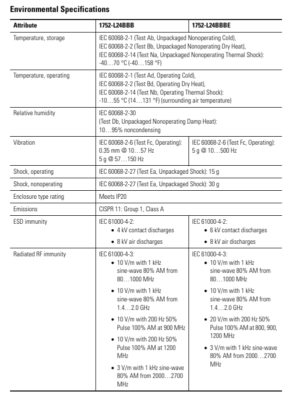
Interpretation of Status Indicators and Troubleshooting
1. Meaning of core indicator lights (sorted by classification)
(1) Module status (MS) indicator light
Suggestions for handling the meaning of indicator light status
Turn off the power supply and check the power wiring. Restart the power supply
Green constantly on, normal operation (Run mode), no operation required
Green flashing standby mode (Idle) to confirm if the configuration is complete
Red flashing can restore faults (such as configuration errors). Check the switch configuration and reset the configuration data
The red light is constantly on and cannot be restored due to a fault (such as hardware damage). Check the wiring, eliminate interference, and contact after-sales service
Red green alternating flashing self-test/configuration download waiting for completion. If it continues to flash, it needs to be reconfigured
(2) Network status indicator light
DeviceNet (NS D): Green constant light=online and connected, red constant light=MAC address conflict/bus disconnection, address and cable need to be checked;
EtherNet/IP (NS E, BE only): Green constant light indicates Ethernet connection, red constant light indicates IP address conflict, IP needs to be reassigned.
(3) I/O status indicator light
Yellow constant light=signal normal, red constant light/flashing=circuit fault (such as disconnection, short circuit, overcurrent), wiring and load need to be checked.
2. Interpretation of Display Screen Information
Normal state: Display node address (00~63), standalone mode displays "nd";
Fault status: alternately display error codes and node addresses (such as F0=MAC conflict, F1=bus disconnection);
Special function: Press the "Service Switch" to display the security configuration signature (verifying that the program has not been tampered with), press the "IP Display Switch" to display the Ethernet IP.
Key specifications and supporting resources
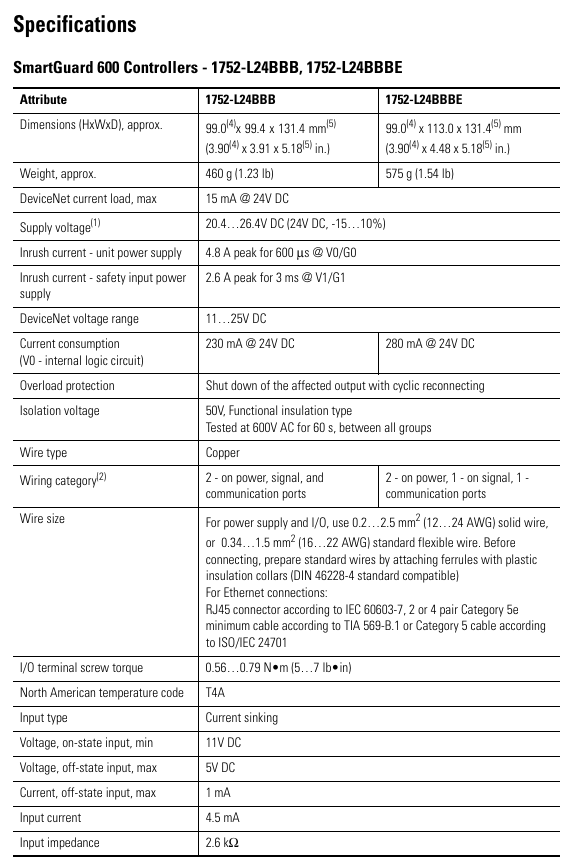
1. Core technical parameters
Specification item 1752-L24BBB 1752-L24BBBE
Size (HxWxD) 99x99.4x131.4mm 99x113x131.4mm
Weight 460g 575g
Working temperature -10~55 ℃ (14~131 ℉) same as left
Protection level IP20, same as left
Input current 4.5mA (per channel) same as left
Output current 0.5A (per channel, maximum) same as left
Ethernet speed -10/100Mbps (full/half duplex)
2. Supporting resources
Key manuals:
SmartGuard 600 User Manual (1752-UM001): Controller Configuration and Troubleshooting;
SmartGuard 600 Safety Reference Manual (1752-RM001): Safety Concepts and PFD/PFH Calculations;
tool
Configuration software: RSNetWorx for DeviceNet (DeviceNet configuration), BOOTP tool (IP configuration);
Core safety operation reminder
Prohibited behavior:
Test outputs cannot be used as safety outputs, and safety signals cannot be transmitted using DeviceNet standard I/O data;
It is prohibited to disassemble/modify the controller (which may damage safety functions);
Do not allow the 24V DC line to accidentally touch the output terminal to avoid starting the load.
Wiring specifications:
Input/output cables should be arranged separately from high-voltage/high current cables to avoid interference;
Stranded wires require the installation of DIN 46228-4 standard insulated Ferrules (non-standard Ferrules may not match the terminals).
- ABB
- General Electric
- EMERSON
- Honeywell
- HIMA
- ALSTOM
- Rolls-Royce
- MOTOROLA
- Rockwell
- Siemens
- Woodward
- YOKOGAWA
- FOXBORO
- KOLLMORGEN
- MOOG
- KB
- YAMAHA
- BENDER
- TEKTRONIX
- Westinghouse
- AMAT
- AB
- XYCOM
- Yaskawa
- B&R
- Schneider
- Kongsberg
- NI
- WATLOW
- ProSoft
- SEW
- ADVANCED
- Reliance
- TRICONEX
- METSO
- MAN
- Advantest
- STUDER
- KONGSBERG
- DANAHER MOTION
- Bently
- Galil
- EATON
- MOLEX
- DEIF
- B&W
- ZYGO
- Aerotech
- DANFOSS
- Beijer
- Moxa
- Rexroth
- Johnson
- WAGO
- TOSHIBA
- BMCM
- SMC
- HITACHI
- HIRSCHMANN
- Application field
- XP POWER
- CTI
- TRICON
- STOBER
- Thinklogical
- Horner Automation
- Meggitt
- Fanuc
- Baldor
- SHINKAWA
- Other Brands
- UniOP
- KUKA
- Iba
-
 AB 1494U-D100 Smart Motor Controller
 -
 Omron NA5-7W001B-V1 Touch Screen HMI
 -
 Fanuc A16B-1000-0400/01A CNC Control Board
 -
 Omron CV2000-CPU01-EV1 PLC CPU Unit
 -
 Eaton XV-102-B4-35TQRF-10-PLC Touch Panel
 -
 Siemens 6FX1121-3BB01 SINUMERIK Board
 -
 SCE M68-2000 2 Axis CNC Servo Controller
 -
 Omron R88M-K20030T-BS2 AC Servo Motor
 -
 Omron G3NH-4150B Solid State Relay
 -
 BITICINO MA250 T7313A Megatiker PLC Disconnector
 -
 IFM 2MSTR AS-i PROFIBUS DP Gateway
 -
 Danfoss VLT 3022 175H1238 Variable Speed Drive
 -
 PASABAN MTC-3052 FAST I/O Module
 -
 Allen Bradley 1746-A7 SLC 500 Chassis
 -
 Mitsubishi NF1600-SEW MCCB
 -
 Schneider LTMR100EBD Motor Management Controller
 -
 Yokogawa AIP121-S3 Analog Input Module
 -
 Siemens 6ES7135-4LB02-0AB0 ET200S AO Module
 -
 Motor Power SKA DDR 148-240 Torque Motor
 -
 OMRON CS1H-CPU63-EV1 PLC CPU Unit
 -
 ABB UFC921A101 Main Control Board
 -
 ABB UFC921A Main Control Unit
 -
 ABB UFC911B108 Drive Main Control Unit
 -
 ABB UFC911B106 Drive Main Control Unit
 -
 ABB UFC911B101 Drive Main Control Unit
 -
 ABB UFC765AE102 Drive Control Interface Board
 -
 ABB UFC762AE101 I/O and Communication Extension Board
 -
 ABB UFC760BE41 I/O and Communication Extension Board
 -
 ABB UFC760BE145 I/O and Communication Extension Module
 -
 ABB UFC721BE101 Fieldbus Communication Adapter Module
 -
 ABB UFC721AE101 3BHB002916R0101 Network Interface
 -
 ABB UFC718AE101 HIEE300936R0101 Communication Module
 -
 ABB UDC920BE01 3BHE034863R0001 Communication Module
 -
 GE IS420UCSCH1A-F-VO.1-A Controller Module
 -
 GE UCSC H1 IS420UCSCH1A Controller Station Card
 -
 ABB UCD240A101 3BHE022287R0101 Process Controller
 -
 ABB UCD224A103 Process I/O Module
 -
 ABB UCD224A102 Analog Input Module
 -
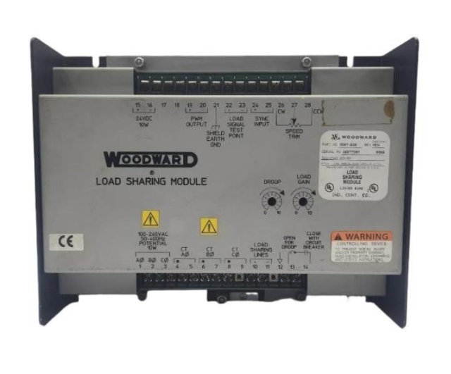 WOODWARD 9907-838 Load Sharing Module
 -
 B&R X20CP1485-1 Industrial PC CPU Module
 -
 ELAU MC-4/11/22/400 4-Axis Servo Drive
 -
 ELAU C600/10/1/1/1/00 Configurable Safety Relay
 -
 BENTLY 60R/SIM01 Proximitor Power Supply
 -
 BENTLY 60R/PPM01 Protection Processing Module
 -
 BENTLY 60R/PNL01 Operator Control Panel
 -
 BENTLY 60R/PIM01 Panel Interface Module
 -
 BENTLY 60R/INP07 Isolated DC Input Module
 -
 BENTLY 60R/INP01 4-Channel Analog Input Module
 -
 BENTLY 60R/CMM01 Communication Multiplexer Module
 -
 BENTLY 60R/CHA02 System Chassis Rack Enclosure
 -
 BENTLY 60R/CGW01 Condition Monitoring Gateway
 -
 Pacific Scientific P70360-SDN Servo Motor
 -
 HONEYWELL 05701-A-0284 Signal Conditioner
 -
 YOKOGAWA NFCP501-W05 Pressure Transmitter
 -
 ABB CI541V1 3BSE0146666R1 Control Interface
 -
 ABB DSTC176 57310001-KT Terminal Base Unit
 -
 ABB DSDP170K02 3BSE019925R1 Analog Input Module
 -
 ABB DSBC173 57310001-KH Terminal Base Unit
 -
 ABB DSAI130K01 5730-030-UC Thermocouple Input
 -
 ABB DSRF182 57310255-AL Relay Output Module
 -
 ABB SC520 3BSE003816R1 Compact PLC
 -
 ABB DSDP140A 57160001-ACT Analog Input Module
 -
 ABB DSAI130 57120001-P Analog Input Module
 -
 ABB SCYC55830 3AFE58063282 MCCB
 -
 Fireye 95DSS3-1CEX UV Flame Scanner
 -
 ABB DSDP170 57160001-ADF Analog Input Module
 -
 ABB CI532 3BSC140120R1 Communication Interface
 -
 ABB DSAO120A 3BSE018293R1 Analog Output Module
 -
 ABB CI869K01 3BSE049110R1 Ethernet Interface
 -
 ABB CI522A 3BSE018460R1 PROFIBUS DP Master
 -
 GUTOR OP6257 Rectifier Control Unit
 -
 Meggitt C327845-11 Gas Shutoff Valve
 -
 ABB SACO64D4 4-Pole Digital Annunciator Unit
 -
 ABB CI522AK04 3BSE018451R1 PROFIBUS DP Module
 -
 ABB DSAI130DK01 3BSE020828R1 Temperature Input Module
 -
 ABB CI546 3BSE012610R1 PROFIBUS DP Master Module
 -
 ABB SC510 3BSE003832R1 Compact PLC Controller
 -
 ABB CI540 3BSE001077R1 PROFIBUS DP Slave Module
 -
 ABB CI532V03 3BSE003828R1 AF 100 PROFIBUS DP Master
 -
 ABB DSBC172 57310256-EL Digital Input Terminal Base
 -
 Rexroth VT2000-5X Frequency Converter AC Drive
 -
 GE MAVS01L1AB0751D-140393N Soft Starter
 -
 ABB REF615 HBFDACADNAA1BCN1XE Relay
 -
 ABB SACO16D1 1-Pole Digital Annunciator Unit
 -
 ABB UNITROL 1000 3BHE014557R0003 Static Excitation System
 -
 Woodward 8273-1011 Electro-Hydraulic Actuator
 -
 Eaton MC2-442-57CQB-1-2A Molded Case Circuit Breaker
 -
 Siemens 3AY1715-6L VS30029P VS30041 Auxiliary Contact Block
 -
 ABB PCD235B101 3BHE032025R0101 Digital I/O Control Module
 -
 Socapel PAM-R1R-H8F-AP-P V10800 Programmable Axis Manager
 -
 Rexroth VT-HNC100-1-23N-08-P-0 Digital Hydraulic Amplifier
 -
 Woodward 5448-890 SPM-D10 Digital Synchronizer
 -
 TDK-Lambda HWS1500-24 Industrial Power Supply
 -
 Land M2300/1100C-V Infrared Pyrometer
 -
 Lantronix 080-332-000-R Industrial Device Server
 -
 LED E14 3W Miniature LED Lamp
 -
 LEM LC100S/SP7 Hall Effect Current Sensor
 -
 Lenel LNL-1320 Dual Reader Interface Module
 -
 Lenze L5311 Industrial Control Module
 -
 Lenze EPZ-10203 Safety Controller
 -
 Lenze EPL10200 Industrial Drive Module
 -
 Lenze EPL-10200-XX Drive Controller
 -
 Lam Research 810-801237-021 Industrial Part
 -
 Lam Research 810-073479-215 Precision Part
 -
 Lam Research 853-001983-110 Assembly Data
 -
 Lam Research 810-017034-005 Semiconductor Part
 -
 Lambda LZS-A1500-3 AC-DC Power Module
 -
 Lambda LZS-1500-3 Industrial Power Supply
 -
 LAM 810-072907-005 Chamber Interface Control Module
 -
 LAM 810-068158-014 Semiconductor Process Control Module
 -
 LAM 810-800081-018 Vacuum System Interface Module
 -
 LAM 810-068158-013 Semiconductor Control Module
 -
 Leybold CM330 Vacuum Gauge Controller
 -
 Leybold 850-400-G1 Vacuum Pump Module
 -
 LIFTMASTER 71-1550B18LGH Electric Actuator
 -
 LKB Bromma 2211 Pressure Sensor
 -
 LLASERGAS AO2000 LS25 12944-E Gas Analyzer Module
 -
 Load Controls PH-3A Three-Phase Power Sensor
 -
 Ludlum 2401-P Pancake GM Survey Meter
 -
 LUST VF1410LHFS41 AC Servo Drive
 -
 LUTZE UBE-FL/34M Terminal Block Contact
 -
 Marposs E78 Dynamic Balancing Controller
 -
 LENZE E84AVSCE1534VX0 Servo Drive Controller
 -
 LENZE EVF8212-E Frequency Inverter Drive
 -
 LENZE EA-4/10 Drive Expansion Module
 -
 LENZE BG10 Brake Module
 -
 LEUZE DDLS 200/200.1-50-M12 Data Link Data
 -
 LEUZE DDLS 200/200.2-50-M12 Optical Data


