
Rockwell Automation SmartGuard 600 Controller
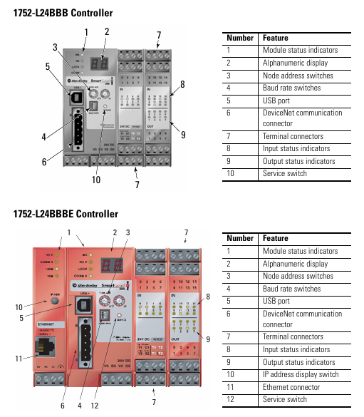
Controller positioning: Programmable Electronic Safety System (PES), supporting 16 digital inputs, 8 digital outputs, 4 test pulse outputs, 1752-L24BBBE with additional support for EtherNet/IP communication;
Safety certification: meets high safety level requirements - IEC 61508 SIL 3, ISO 13849-1 PL (e), EN 954-1 CAT 4, suitable for hazardous environments (North American Class I Div 2 Groups A-D).
Rockwell Automation SmartGuard 600 Controller
Basic and Controller Core Positioning
1. Basic information
Document purpose: To guide the installation, parameter configuration, wiring, and status interpretation of safety controllers, suitable for deployment in industrial safety scenarios such as emergency stop and safety door monitoring;
Controller positioning: Programmable Electronic Safety System (PES), supporting 16 digital inputs, 8 digital outputs, 4 test pulse outputs, 1752-L24BBBE with additional support for EtherNet/IP communication;
Safety certification: meets high safety level requirements - IEC 61508 SIL 3, ISO 13849-1 PL (e), EN 954-1 CAT 4, suitable for hazardous environments (North American Class I Div 2 Groups A-D).
2. Comparison of Model Differences
Model Core Differences Communication Interface Applicable Scenarios
1752-L24BBB Basic Security Control USB+DeviceNet Security Scenarios without Ethernet Requirements (such as Single Device Security Monitoring)
1752-L24BBBE adds Ethernet functionality USB+DeviceNet+EtherNet/IP for distributed security systems that require remote Ethernet monitoring (such as production line level security linkage)
Key configurations before installation (mandatory steps)
1. Safety prerequisite requirements
Precautions for hazardous environments:
It is strictly prohibited to plug and unplug wires with electricity (which may cause arcing and explosion). Power must be cut off or the environment must be confirmed to be in a non hazardous area first;
Prohibition of replacing non original components (which may damage Class I Div 2 compatibility);
Battery replacement is only allowed in non hazardous areas.
Electrostatic protection: Before operation, touch a grounded object to discharge electricity, wear an anti-static wristband, prohibit touching circuit board pins, and store in anti-static packaging when idle.
2. Core parameter configuration (power-off operation)
(1) DeviceNet node address setting
Configuration method: Set through the two rotary switches (ten position+one position) on the front of the controller, with a range of 00~63 (default 63);
Software configuration compatibility: If setting the address through RSNetWorx for DeviceNet software, the rotary switch needs to be turned to 64~99;
Key reminder: Avoid duplicate node addresses, otherwise communication errors may be triggered.
(2) DeviceNet communication rate setting
Default speed: 125 kbps, supports three speeds of 125/250/500 kbps, configured through a 4-digit DIP switch:
DIP switch (1-4) communication rate description
OFF-OFF-OFF-OFF 125 kbps default value
ON-OFF-OFF-OFF 250 kbps medium range networking
OFF-ON-OFF-OFF 500 kbps short distance high throughput scenario
The software configuration of ON-ON-OFF-OFF needs to be set through RSNetWorx
Speed and distance matching: The higher the speed, the shorter the supported cable length (such as 75m for flat cables and 100m for thick cables at 500 kbps), which needs to be selected according to the network size.
(3) EtherNet/IP IP Address Setting (1752-L24BBBE only)
Default mode: BOOTP enabled, IP needs to be allocated through BOOTP server (recommended Rockwell free tool, download link: http://www.ab.com/networks/bootp.html );
Configuration steps:
Run the BOOTP tool and double-click on the device MAC address;
Enter the target IP in the pop-up window and click confirm;
The IP address of the controller can be viewed on the display screen through the front "IP Address Display Switch" (long press for more than 1 second), and error code "n4" indicates abnormal Ethernet configuration.
Controller installation and wiring specifications
1. Physical installation (DIN rail fixation)
Installation requirements:
Only supports EN 50022 standard DIN rails (35x7.5mm or 35x15mm), horizontal installation (vertical installation may affect heat dissipation);
Heat dissipation gap: at least 50mm (2.0in) up and down, and at least 5mm (0.20in) left and right, avoiding installation above heating equipment;
Installation steps:
Hang the top card slot of the controller on the DIN rail;
Press the bottom of the controller and tighten the bottom buckle (1752-L24BBB single buckle, 1752-L24BBBE double buckle);
Install end plates at both ends of the guide rail to ensure stability.
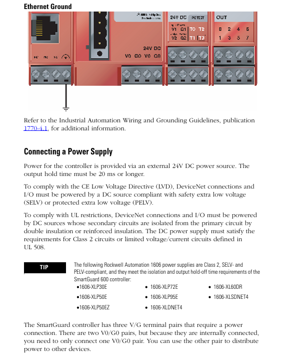
Grounding requirements: Chassis grounding is achieved through DIN rails, which require the use of galvanized yellow chromium steel rails (aluminum/plastic rails may cause poor grounding), and the rails should be fixed every 200mm (7.8in).
2. Power wiring (safety power supply is the core)
Power specifications:
External power supply: 24V DC (allowable range 20.4~26.4V DC), output holding time ≥ 20ms;
Safety compliance: Must meet SELV/PELV (CE LVD), Class 2 (UL 508), and recommend Rockwell 1606 series power supplies (such as 1606-XLP30E, 1606-XL60DR);
Terminal wiring:
The controller includes 3 sets of V/G terminals (V0/G0: internal logic power supply; V1/G1: Input and test output power supply; V2/G2: Safe output power supply);
The V0/G0 two sets of terminals are internally connected, only one set needs to be connected, and the other set can be used to distribute power to other devices.
- OMRON
- ABB
- General Electric
- EMERSON
- Honeywell
- HIMA
- ALSTOM
- Rolls-Royce
- MOTOROLA
- Rockwell
- Siemens
- Woodward
- YOKOGAWA
- FOXBORO
- KOLLMORGEN
- MOOG
- KB
- YAMAHA
- BENDER
- TEKTRONIX
- Westinghouse
- AMAT
- AB
- XYCOM
- Yaskawa
- B&R
- Schneider
- KONGSBERG
- NI
- WATLOW
- ProSoft
- SEW
- ADVANCED
- Reliance
- TRICONEX
- METSO
- MAN
- Advantest
- STUDER
- DANAHER MOTION
- Bently
- Galil
- EATON
- MOLEX
- DEIF
- B&W
- ZYGO
- Aerotech
- DANFOSS
- Beijer
- Moxa
- Rexroth
- Johnson
- WAGO
- TOSHIBA
- BMCM
- SMC
- HITACHI
- HIRSCHMANN
- Application field
- XP POWER
- CTI
- TRICON
- STOBER
- Thinklogical
- Horner Automation
- Meggitt
- Fanuc
- Baldor
- SHINKAWA
- Other Brands
- UniOP
- KUKA
- Iba
- Beckhoff
- ADLINK
-
 Rolls-Royce R02TCN-E0L3-00 Remote Controller Features
 -
 Etel SA-IL 03-208 Linear Motor Section
 -
ETEL ILM03-060-3RA-A00 Ironless Linear Servo Motor
-
 ETEL DSCDP321-121-000 Dual Position Controller Board
 -
 Etel DSCDP121-111F-000A Dual Axis Servo Drive
 -
 Etel EA-S0M-400-40/80A-0000-00 AccurET Modular Power Supply
 -
 Etel TMB+0291-150-RO-00000-0A0 Rotor
 -
 ETEL DSCDP131-111F-000A Position Controller
 -
 ETEL DSC2P154-421F-000A Servo Drive
 -
 ETEL DSO-SER211-000 Add-On Power Board for Servo Amplifier
 -
 ETEL 613712-05 4-Axis Control Assembly
 -
 ETEL P2M-300-07/15A Accuret Position Controller
 -
 ETEL LMP07-100-3TAS-229 Motor Ruler Primary Part
 -
 ETEL 569866-03 ASME-RTMA014 Motor
 -
 ETEL DSCDP131-111-000 Dual Position Controller
 -
 ETEL DSB2S134-211E-000H Digital Servo Amplifier
 -
 ETEL DSCDP121-111F-000A DSC Dual Controller
 -
 ETEL DSC2P154-421E-000A Servo Drive
 -
 ETEL DSCDP121-111C-000A Regulator – Stable Power Control
 -
 ETEL DSC2P131-111B-000D Driver Board
 -
 ETEL ILM03-060-3RA-A00 Linear Motor
 -
 ETEL EA-S0M-300-40/80A-0090-00 Power Supply Module
 -
 Etel DSCDP131-111-000 Position Controller
 -
 ETEL DSC2P121-111E-001A Digital Servo Amplifier
 -
ETEL DSB2P101-121E-009H Position Controller
-
 ETEL IWM040-0128-00 Ironcore Linear Motor Magnetic Way
 -
 ETEL AccurET EA-S0M-400-40/80A-0000-00 Modular Power Supply
 -
ETEL LMC11-050-3TA-S10C Motion Controller
-
 ETEL LMC11-050-3TA-250A Controller Module
 -
 ETEL DSB2P101-121E-009H Digital Servo Amplifier Position Controller
 -
 ETEL AccurET Modular 400 Position Controller
 -
 ETEL DSA2 Digital Servo Amplifier
 -
ETEL DSC2P154-421-000 Servo Drive
-
 ETEL DSO-PWS121-003 Power Supply Module
 -
 ETEL 0348M-070-02D-004 Linear Encoder
 -
 ETEL DSC2P131-111-000 Linear Servo Amplifier – 10Arms/30Arms
 -
ETEL DSC2P131-121-000 Digital Servo Amplifier
-
ETEL DSB2P131-111E-000H Digital Servo Amplifier
-
ETEL DSO-PWS111-000 Power Supply Module
-
ETEL LMC11-050-3TA-S41C Linear Motor Module – High Thrust Density
-
 ETEL EA-P2M-300-07/15A Drive Specs
 -
 ETEL DSO-RAC200A-011D Dual Position Controller Rack
 -
 ETEL Short-Stroke Actuator ID809786-03
 -
 ETEL DSCDM332-111-000 Servo Controller Specs
 -
 ETEL DSCDL332-131-000A Position Controller
 -
 ETEL LMP07-100-3TAS-229 Linear Motor
 -
ETEL LMA11-120-3ZA-359C Linear Motor
-
ETEL DSA2S211ZA-018A Digital Servo Amplifier
-
 ETEL EA-P2M-300-07/15A AccurET Controller
 -
ETEL LMB06-050-2QA-239B Linear Motor Guide
-
 ETEL DSCDP334‑421‑000 Servo Drive – High‑Power Digital Controller Positioner
 -
ETEL DSCDP121‑111E‑000A Dual Driver Board – High‑Density Motion Control Module
-
 ETEL DSA2 S1B22A Digital Servo Amplifier – High‑Efficiency Drive for Industrial Motors
 -
 ETEL DSCDM342‑111‑000 Servo Amplifier – Multi‑Axis Digital Drive
 -
ETEL MWA120‑0512‑00B 512mm Linear Motor Magnet
-
ETEL EA‑P2M‑300‑07/15A‑0100‑01 AccurET Modular Position Controller – Medium‑Power Drive
-
Etel DSC2P141‑111‑000 568425‑01 Digital Servo Amplifier – Compact High‑Performance Drive
-
 Etel EA‑P2M‑400‑10/20A‑0000‑01 AccurET Modular Position Controller – High‑Voltage Drive
 -
ETEL DSC2P142‑111‑000 Digital Servo Amplifier – Compact Position Controller
-
ETEL DSDH153‑121C‑001D Digital Servo Drive – High‑Power Motion Control
-
ETEL DSB2P131 & DSO-CAN111A Servo Amplifier Set
-
ETEL DSA2S211ZA-018A Digital Servo Amplifier
-
ETEL DSMAX212-111-001 568540-01 DSMAX2 Servo Controller
-
 ETEL TMB+0291-150 Torque Motor Stator Assembly
 -
 ETEL EA-S0M-300-40/80A AccurET PSU
 -
ETEL DSO-PWR112C-000B Power Supply Module
-
ETEL DSC2P141-111-000 Linear Servo Amplifier
-
ETEL DSB2S154-211-000H Servo Amplifier
-
ETEL DSCDP121-122-000 Digital Controller
-
ETEL DSCDP121-111E-000A Dual Position Controller
-
ETEL DSCDM332-111-000 Linear Servo Controller
-
 ETEL DSB2P134-111E-000H Servo Amplifier
 -
ETEL DSCDP132-111-000 Control Board Guide
-
 ETEL DSB2S154-211E-000H Servo Amplifier
 -
ETEL EA-SOM-300-40/80A Power Supply Module
-
ETEL ILM12-060-3PD-R20C Linear Motor with IWM Ways
-
 ETEL P2M-300-07 AccurET Position Controller
 -
ETEL DSB2P124-111E-000H Servo Amplifier
-
 ETEL EA-P2M-048-05/10A Position Controller
 -
 ETEL EA-S0M-300-40/80A Power Supply Module
 -
ETEL MWA070-0256-20B Linear Motor Magnet Guide
-
ETEL MWD070‑0128‑21A Linear Motor – Compact Ironless Linear Motor for High‑Speed Precision
-
ETEL DSB2P124‑211E‑000H Digital Servo Amplifier – 300 VDC Slave Drive for High‑Voltage Systems
-
ETEL MWD100‑0128‑00B Linear Motor – High‑Force Ironless Linear Motor for Precision Motion
-
ETEL AccurET EA‑S0M‑400 & P2M‑400‑05/10A Drive Module
-
ETEL EA‑S0M‑400‑40/80A‑0000‑00 AccurET Power Supply – High‑Power DC Supply for Motion Systems
-
ETEL MWA050‑0128‑20B Linear Motor Magnet – High‑Force Magnet Assembly for Linear Motors
-
ETEL DSB2S121‑111E‑000H Digital Servo Amplifier – High‑Current Drive for Demanding Motion
-
 ETEL DSCDM332‑111C‑000B Digital Position Controller DSCDM – High‑Density Motion Module
 -
ETEL EA‑P2M‑048‑2.5/5A‑0100‑01 AccurET Modular Position Controller
-
 ETEL DSC2P121-111E-001A Digital Servo Controller – High‑Precision Motion Control
 -
ETEL MWA050-0128-20B Linear Motor Magnet
-
 ETEL DSB2P142-111E-000H Drive Specs
 -
 ETEL DSB2S234-111E-000H Servo Amplifier
 -
 ETEL EA-P2A-400-10-20A Position Controller
 -
ETEL DSB2 Digital Servo Amplifier Controller DSB2P142-111E-000H SN 014661437
-
ETEL EA-S0M-400-40/80A-0000-00 AccurET Power Supply Module 650140-01
-
ETEL DSB2P131-111E-000H Servo Amplifier
-
ETEL EA-P2M-400-10/20A AccurET Controller
-
ETEL DSDP324-322F-000C Dual Motor Driver
-
ETEL DSB2S154-211E-000H Digital Servo Amplifier Drive
-
ETEL DSO-PWS111B-000C Power Supply Board 1130E-070-018
-
ETEL DSCDP324-322G-000A Servo Amplifier
-
ETEL DSB2P142-111E-000H Servo Amplifier Drive
-
 ETEL EA-P2M-400-15/40A & EA-S0M-400 Drive Set
 -
ETEL DSB2P142-111E-000H Digital Servo Amplifier
-
ETEL LMG15-070-3QC-H11 Linear Motor
-
 ETEL TMA0140-070-3RB-S62B Torque Motor
 -
ETEL DSA2S211ZA Digital Servo Amplifier
-
ETEL AccurET EA-P2M-300-4/7.5A-0100-01 Modular Position Controller
-
 ETEL DSCDL332-131C-000A Servo Control Board
 -
ETEL DSCDP324-322F-000C Dual Motor Driver
-
 ETEL EA-P2M-400-10/20A Position Controller
 -
ETEL DSC2P121 and DSO-HIO33 Servo Amplifier Set
-
 ETEL EA-P2M-400-15/40A AccurET Drive
 -
ETEL EA-P2M-300-07/15A Position Controller
-
ETEL EA-P2M-048-05/10A-0100-01 Servo Drive
-
 ETEL EA-S0M-300-40/80A Servo Drive Guide
 -
ETEL DSB2P131-111E-000H Digital Servo Amplifier
-
ETEL DSCDP334-421-000 Servo Drive Guide
-
ETEL EA-S0M-300-40 80A-0000-00 Motion Control Module
-
 ETEL UltimET Light Motion Controller EU-LGP-0-0-1000-01 Multi-Axis
 -
 ETEL DSO-RAC601-029 Controller Rack
 -
ETEL DSMAX212-121C-000C Board
-
 ETEL DSCDL132-212B-000C Position Controller
 -
ETEL TMB0291-050-3TDS-E82 Torque Motor
-
 ETEL DSMAX212-121-000 Board
 -
ETEL DSB2P131-111E-000H Digital Servo Controller Amplifier Unit


