
YOKOGAWA WT1801R series precision power analyzer communication interface
YOKOGAWA WT1801R series precision power analyzer communication interface
Overview
The communication interface user guide for YOKOGAWA WT1801R, WT1802R, WT1803R, WT1804R, WT1805R, and WT1806R series precision power analyzers was first released in October 2024. The core of the document revolves around the three communication interfaces of the instrument (Ethernet, USB, GP-IB), providing detailed explanations of interface functions, configuration methods, programming instructions, and status reporting mechanisms. It also provides a document system, terminology conventions, and global contact information, aiming to help users achieve remote control and data exchange of the instrument through PC.
Core Communication Interface Functions and Configuration
1. Ethernet interface
(1) Core Features and Specifications
Compatibility: Compliant with IEEE 802.3 standard and supports TCP/IP (VXI-11) communication protocol.
Connection capability: Supports connection with PC through hub/router, does not support cross line direct connection; The maximum number of simultaneous connections is limited by network devices.
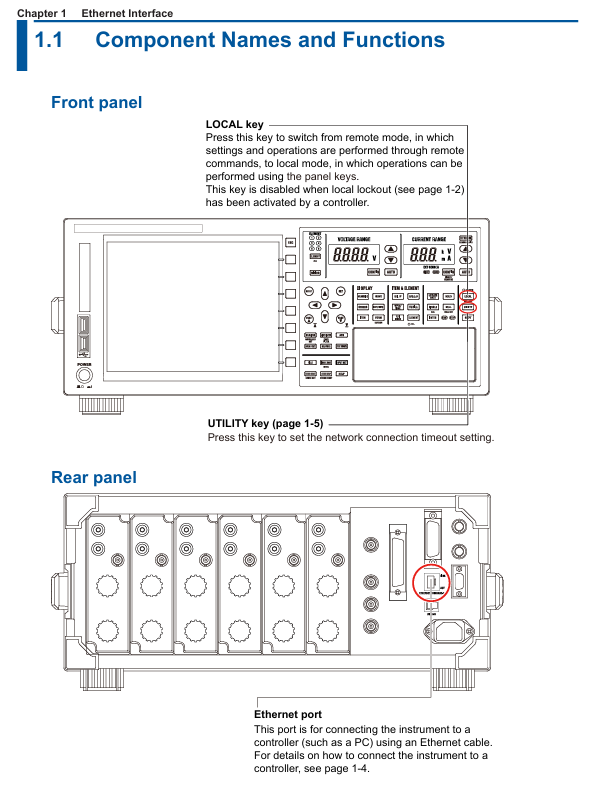
Remote control switch: Receive: Communicate: REMote ON/OFF command to switch between remote/local mode. In remote mode, only the LOCAL key is available (disabled when local is locked).
Timeout setting: The network connection timeout time can be set (1-3600 seconds or "infinite"), and the connection will be automatically disconnected after timeout. The default is "infinite".
(2) Configuration steps
Hardware connection: Use shielded twisted pair (STP) to connect the Ethernet port of the instrument Rear panel to the hub/router.
Enter the configuration menu: Press the UTIL key on the panel → click the Remote Control soft key → select the Network soft key to enter the network settings interface.
TCP/IP settings: IP address, subnet mask, and default gateway need to be configured (refer to section 20.2 of the IM WT1801R-02EN user manual for detailed steps).
Timeout setting: In the network settings interface, adjust the timeout time (Infinite or 1-3600s) through the cursor keys.
2. USB interface (USB-TMC)
(1) Core Features and Specifications
Compatibility: Compliant with USB 3.0 standard, supports USB-TMC (Test Measurement Class) protocol, requires installation of Yokogawa dedicated USB driver.
System requirements: Only supports Windows 10/11 system, PC needs to install communication library (TMCTL) and USB device driver (official website) https://tmi.yokogawa.com/ Downloadable).
Remote mode switching: Consistent with the Ethernet interface logic, it can be switched using the COMMunicate command or LOCAL key, and supports local locking.
Uniqueness: Only one USB device connection is supported at a time and cannot be used simultaneously with Ethernet or GP-IB interfaces.
(2) Configuration steps
Hardware connection: Connect the USB port of the instrument Rear panel to the PC using a USB Type B cable, and wait for 20-30 seconds after booting up before operating (to avoid damaging the device).
Driver installation: Download and install the Yokogawa USB TMC driver from the official website, and prohibit the use of third-party drivers.
View device serial number: Press the UTIL key → click on the Remote Control soft key → select the USB soft key to view the device serial number required for USB-TMC communication.
3. GP-IB interface (IEEE 488)
(1) Core Features and Specifications
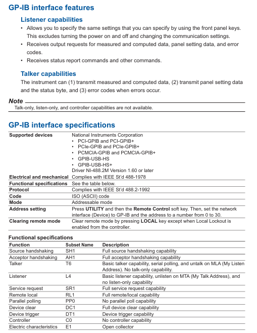
Compatibility: Compliant with IEEE 488-1978 (Mechanical/Electrical) and IEEE 488.2-1992 (Protocol) standards, supports National Instruments GP-IB cards (such as PCIe GPIB, GPIB-UB-HS+).
Functional subset: Supports SH1 (source handshake), AH1 (receive handshake), T6 (basic talker), L4 (basic listener), SR1 (service request) and other functional subsets, without controller capability.
Address setting: The address range is 0-30, and each device on the bus needs to be assigned a unique address to avoid conflicts.
Connection restriction: The bus can connect up to 15 devices (including controllers), with a single cable length of ≤ 2 meters and a total length of ≤ 20 meters.
(2) Configuration steps
Hardware connection: In the shutdown state, use a 24 pin GP-IB cable to connect the GP-IB port of the instrument Rear panel to the GP-IB board of the PC, and tighten the connector screws.
Address configuration: Press the UTIL key → click the Remote Control soft key → select the GP-IB soft key, and set the address (0-30).
Interface response: Supports interface messages such as IFC (interface clearing), REN (remote enable), SDC (selected device clearing), etc. Please refer to section 3.5 of the document for specific response logic.
Fundamentals of Programming and Instruction System
1. Core programming concepts
Message types: divided into "program messages" (instructions sent by the PC to the instrument, such as configuration instructions and query instructions) and "response messages" (data returned by the instrument to the PC, such as measurement results and status information).
Instruction structure:
Common instruction: IEEE 488.2 standard instruction, starting with * (such as * CLS clearing status register, * IDN?)? Check the instrument model).
Composite instruction: Instrument specific hierarchical instruction, separated by: (e.g. DISPlay: MODE NUMeric to set display mode to numerical display).
Simple instruction: Non hierarchical independent instruction (such as HOLD to set data hold).
Data format: Supports decimal (NR1/NR2/NR3), physical quantities (with units, such as 100V), registers (binary/octal/hexadecimal), strings (user-defined, such as file names), and other formats.
2. Core instruction grouping and functions
Chapter 5 of the document provides a detailed list of 23 instruction groups, covering scenarios such as interface control, display settings, data storage, measurement and calculation. The key instruction groups are as follows:
Instruction group core instruction example function description
COMMunicate Group :COMMunicate:REMote ON
: Communicate: READer OFF controls remote/local mode, sets response with header information
DISPlay Group :DISPlay:MODE WAVE
DISPlay: WAVE: TDIV 5MS Set display mode (waveform/value/trend), adjust waveform timeline scale
FILE Group :FILE:SAVE:NUMeric "DATA1"
: FILE: LOAD: SETup "SET1" saves numerical data to a file, loads instrument settings file
MEASure Group :MEASure:AVERaging:STATE ON
MEASure: FUNCtion1: EXPResolution "URMS (E1)" Enable data averaging function and define user-defined measurement functions
NUMeric Group :NUMeric[:NORMal]:VALue?
NUMeric: FORM ASCII queries numerical measurement data, sets data output format (ASCII/FLOAT)
STORe Group :STORe:START
: STORe: FILE: CONVert: EXECUTE "STR1" Start storing data and convert stored data to CSV format
Common Command *IDN?
*OPC? Query instrument identification (model/serial number), query operation completion status
3. Synchronization and status reporting
Synchronization mechanism: through * WAI (waiting for operation completion),: Communicate: WAIT (waiting for specified event), * OPC? (Operation completion query) Avoid instruction execution conflicts and ensure data consistency.
Status report: includes status bytes, standard event registers, extended event registers, and error queues, supported through: Status: ERRor? Query error codes and messages through * STB? Query status bytes to help locate communication or operational anomalies.
Modbus/TCP communication (extended functionality)
Function Overview: Supports Modbus/TCP protocol, can communicate with client devices (such as PLC, SCADA systems), and achieve register read/write and data interaction.
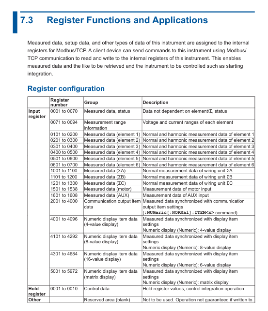
Register configuration: Chapter 7 of the document provides detailed definitions of register addresses and functions, covering measurement data, instrument status, configuration parameters, etc. It supports reading real-time data such as voltage, current, power, etc. through Modbus commands.
Communication process: The client needs to connect to the instrument's IP address and port (default 502) through TCP, and send Modbus function codes (such as 03H read hold registers) to achieve data exchange.
Precautions and Compatibility
Interface exclusivity: Ethernet, USB, and GP-IB interfaces cannot be used simultaneously and need to be manually switched or specified as a unique active interface through commands to avoid command conflicts.
Driver and library dependencies: USB and Ethernet interfaces require the installation of Yokogawa Communication Library (TMCTL) and drivers, and only support Windows systems, not compatible with third-party drivers.
Cable and Connection: GP-IB requires cables that comply with IEEE standards, Ethernet needs to be connected through a hub/router (cross wiring is not supported), and USB needs to be plugged in and unplugged after the instrument is turned on and stabilized.
Legacy compatibility: Chapter 8 of the document provides instructions for compatibility with WT1600, WT1800, and WT1800E series legacy instruments, facilitating smooth migration for existing users.
- OMRON
- ABB
- General Electric
- EMERSON
- Honeywell
- HIMA
- ALSTOM
- Rolls-Royce
- MOTOROLA
- Rockwell
- Siemens
- Woodward
- YOKOGAWA
- FOXBORO
- KOLLMORGEN
- MOOG
- KB
- YAMAHA
- BENDER
- TEKTRONIX
- Westinghouse
- AMAT
- AB
- XYCOM
- Yaskawa
- B&R
- Schneider
- KONGSBERG
- NI
- WATLOW
- ProSoft
- SEW
- ADVANCED
- Reliance
- TRICONEX
- METSO
- MAN
- Advantest
- STUDER
- DANAHER MOTION
- Bently
- Galil
- EATON
- MOLEX
- DEIF
- B&W
- ZYGO
- Aerotech
- DANFOSS
- Beijer
- Moxa
- Rexroth
- Johnson
- WAGO
- TOSHIBA
- BMCM
- SMC
- HITACHI
- HIRSCHMANN
- Application field
- XP POWER
- CTI
- TRICON
- STOBER
- Thinklogical
- Horner Automation
- Meggitt
- Fanuc
- Baldor
- SHINKAWA
- Other Brands
- UniOP
- KUKA
- Iba
- Beckhoff
-
 Basler D90 96801 100 PCB Card
 -
 Basler XR2002F Voltage Regulator (110 VAC, 48-480 Hz)
 -
 Basler SR8A-2B14B3A Regulator
 -
 Basler 9561500100 Module
 -
 Basler DECS-400 BE1-11 System
 -
 Basler DECS-100-B15 Excitation Control
 -
 Basler SCP 210 Frequency Controller
 -
 Basler SR4A-2B15B3A Static Voltage Regulator
 -
 Basler BE1-32R Power Relay
 -
 Basler PIA2400-17GM Power Interface Adapter
 -
 Basler MVC 232 Manual Voltage Control Module
 -
 Basler SSR 32-12 Static Voltage Regulator
 -
 Basler 5MW AVR Generator Voltage Regulator
 -
 Basler VR63-4B Voltage Regulator
 -
 Basler DECS-100-A05 AVR for Engine Generator
 -
 Basler DECS-100-B15 Automatic Voltage Regulator
 -
 Basler BE1-32R Directional Power Relay
 -
 Basler BE1-87B Differential Relay
 -
 Basler UFOV 260A Protective Module
 -
 Basler 9-2614-02-100 PCB Rev M
 -
Basler DECS-100-B15 Digital AVR
-
 Basler 9284900103 PS DECS-400N
 -
 Basler D4N3H1U Intertie Protection
 -
 Basler DECS-100-B15 A15 AVR
 -
 Basler KR4F Voltage Regulator
 -
 Basler BE26434 T14 Transformer
 -
 Basler SR8A-2B15B3A Regulator
 -
 Westinghouse 774B472A12 AR Relay
 -
Basler DECS-100-B15 AVR
-
Basler XR2002F Regulator 110V
-
Basler SR125-E Static Regulator
-
 Basler SSR 125-12 Regulator
 -
 Basler MOC2599 Motor Pot
 -
 Basler BE1-DFPR Feeder Relay
 -
 Basler CBS 305 Current Boost
 -
 Basler BE1-25 AutoSync
 -
 Basler MVC 300 Voltage Control
 -
 Basler BE3-25A AutoSync
 -
 Basler KR7FF Static Regulator
 -
 Basler 90-49000-100 Regulator
 -
 Basler 880 kVA Dry Type Transformer Specs
 -
 Basler Electric BE1-25 Sync-Check Relay Specs
 -
 Basler SSR 125-12 Voltage Regulator Specs
 -
 Basler Electric BE1-851 Overcurrent Relay Review
 -
Basler Electric 149D930G02 Control Sub-Assembly
-
 Basler Electric BE1-81O/UT Frequency Relay Specs
 -
 Basler Electric BE1-51/27C Overcurrent Relay
 -
 Basler Electric 149D956G02 Industrial Component
 -
Basler Electric BE1-51A Overcurrent Relay Specs
-
 Basler Electric BE1-40Q Loss of Excitation Relay
 -
 Basler DECS-200 Excitation Control System
 -
 Basler DECS-200 Voltage Regulator 56-277V AC / 125V DC
 -
Basler BE1-87T Transformer Differential Relay
-
 Basler RDP-110-S1 Protection Relay
 -
 Basler BE1-700V Digital Protective Relay
 -
 Basler BE1-951 Overcurrent Protection System
 -
 Basler DECS-300 Digital Excitation Control
 -
 Basler DECS-200 Digital Excitation Control
 -
 Basler DECS-200-1C Excitation Control System
 -
Basler DECS-200-1L Digital Excitation Control
-
 Basler Electric BE1-GPS Generator Protection System
 -
Basler Electric DECS-200-1C Digital Excitation Controller
-
 Basler Electric DECS125-15 Excitation Control with Power Module
 -
 Basler Electric BE1-87G Differential Relay
 -
 Basler Electric BE1-11 Protection System I5A3M2P2N0EA00
 -
Basler Electric DECS-200-1C Excitation Control System
-
Basler Electric BE1-11g Generator Protection Relay
-
Basler Electric DECS 125-15-B2C1 V2.0.9 Excitation Control
-
 Basler Electric BE1-81O/UT3ED1JA7N2F Frequency Relay
 -
Basler Electric BE1-81O/UT3EE1YB7N1F Frequency Relay
-
 Basler Electric DECS-200-1L Digital Excitation Control System
 -
Basler DECS125-15-B2C1 Excitation Control
-
 Basler 9507900205 SSR Retrofit Voltage Regulator
 -
 Basler BE2000E Digital Voltage Regulator
 -
 Basler BE1-GPS Generator Protection System
 -
Basler DECS-250-CN1CN1N Digital Excitation Control
-
 Basler DGC-2020 Genset Controller
 -
 Basler BE1-81O UT3ED1LA7N0F Frequency Relay (Variant)
 -
 Basler BE1-81O UT3EE1YA9S0F Frequency Relay (Variant)
 -
Basler BE1-81O Over/Under Frequency Relay
-
Basler DECS125-15 Digital Excitation Control
-
Basler Electric BE1-951 Overcurrent Protection System
-
 Basler Electric BE1-700V Digital Protective Relay
 -
 Basler Electric APR63-5 Automatic Voltage Regulator
 -
Basler Electric BE1-851 Overcurrent Protection System
-
Basler Electric DECS-250-LN1SN1N Excitation Control
-
 Basler Electric BE1-87T Transformer Differential Relay
 -
Basler Electric DECS-200-1L Excitation Control System
-
 Basler Electric 9310300100 DECS-300 Excitation Control
 -
 Basler Electric SSE-N 125-4.5KW Shunt Exciter Regulator
 -
 Basler Electric DGC-2020HD-5NS1DNSBA Genset Controller
 -
Basler Electric BE1-81-O/UT3EE1JB7N1F Frequency Relay
-
Basler Electric BE1-81T1EE1WA0N1F Frequency Relay
-
 Basler Electric BE1-25M1EA6PN5R1F Sync-Check Relay
 -
 Basler Electric BE1-GPS Generator Protection System
 -
Basler Electric DECS-250-LN1SN1N Excitation Control Rev V
-
 Basler Electric DECS-250-CN2CN1N Excitation Control
 -
Basler Electric BE1-50/51B-207 Overcurrent Relay
-
Basler Electric DECS-300-C0N0 Excitation Control System
-
Basler Electric DECS-200 Digital Excitation Control System
-
Basler Electric DECS-250-LN1CN1N Excitation Unit
-
Basler Electric DECS-250 LN2SA1D Excitation Unit Specs
-
Basler Electric BE1-87T Transformer Relay Review
-
Basler Electric BE1-11 Protection System
-
Basler Electric BE1-GPS100-E4N1H1N Protection System
-
 Allen-Bradley 442G-MABH-R Safety Module
 -
 Beckhoff CX1030-0111 PLC Assembly Profile
 -
 FANUC IC693CPU364 PLC Module
 -
 Orange Denmark Type 200816 220 PLC Specs
 -
 OMRON C200H-SNT31 Sysmac PLC Module
 -
 Allen Bradley 20AB022A3AYNANC0 PowerFlex 70
 -
 OMRON C200HW-PCU01 Position Control Unit
 -
 ABB AO845A-eA Analog Output Module
 -
 OMRON CJ1M-CPU22 CPU Unit
 -
 Allen Bradley 100-E265ED11 Contactor
 -
 Honeywell 51304511-100 Interface Module
 -
 SOLEXY BXF3S0101N0018 Gateway Module
 -
 OMRON CJ2H-CPU65 CPU Unit
 -
 Automation Direct GS2-45P0 AC Drive
 -
 M68-2000 2-Axis Motion CNC Controller
 -
 OMRON CJ1M-CPU11 V3.0 PLC CPU Unit
 -
 OMRON CJ1W-NC413 4-Axis Positioning Controller
 -
 OMRON 3G2A3-PRO16 Programming Console HMI
 -
 Siemens 3VT8440-2AA04-2GA2 Molded Case Circuit Breaker
 -
 Siemens 3RT5045 Contactor Series
 -
 OMRON C200HS-CPU01-E SYSMAC PLC Controller
 -
 OMRON C500-NC103-E Positioning Control Unit
 -
 OMRON CJ1W-TC001 Temperature Control Unit


